


Quick answer: A hydrogen cylinder case is sized by vent area first: 8% of internal surface, a 0.2 MPa burst disc, two straps at 25 N·m.
Table of contents
- Vent Area Before Wall Thickness
- Three Diameters, Two Straps
- Upright or Lying Down
- Where 0.089 kg/m³ Sends the Gas
- Three Checks Before It Ships
- FAQ
1. Vent Area Before Wall Thickness
A case for a 406 mm cylinder runs 1.35 m long, 6 mm walls, 38 kg empty. Before the tool is cut, fix the total vent area: flatten the six internal faces, measure about 3.0 m², take 8%. That lands at 0.24 m², and every later call on ribs follows from it.
The 8% is a floor, not a clause in a standard. Cut more and the wall section breaks, so a drop test cracks at a hole edge instead of a corner. Cut less and gas trapped beside the shoulder has nowhere to go once the disc lifts at 0.2 MPa.
Split it into three groups rather than one opening: louvers at both lid ends, a slot band on the upper side wall, a grille on top. Flange each hole by 3 mm for bending stiffness, and keep 12 mm of material between neighbours. That rib width gets skipped more often than area, and thin ribs bulge at the hole edges once four units are stacked.
2. Three Diameters, Two Straps
Internal width follows the cylinder: a 230 mm shell in a 260 mm cavity, 325 in 355, 406 in 436, each with 15 mm per side, air plus an 8 mm EPE pad rather than foam alone. Build one cavity to the largest size and small cylinders slide; past 10 mm of travel the straps shear instead of pull.
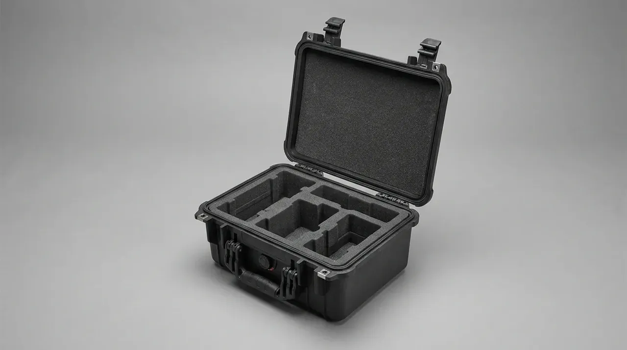
Two straps beat three. Space them 0.55 m apart, the first 0.12 m below the shoulder, the second 0.35 m above the base. A third over-constrains a rigid cylinder: tighten the middle and both ends lift, so the 25 N·m sits behind no load. Run 30 mm webbing with 5 mm padding over a 120° arc and contact pressure stays under 0.3 MPa.
| Cylinder OD tier | Cavity width | Side clearance | Strap arc | Unit weight | Duty |
|---|---|---|---|---|---|
| 230 mm | 260 mm | 15 mm | 0.72 m | 26 kg | short shuttle |
| 325 mm | 355 mm | 15 mm | 1.02 m | 33 kg | general freight |
| 406 mm | 436 mm | 15 mm | 1.28 m | 38 kg | long shell, lying |
| two 406 mm | 900 mm | 15 mm | 1.28 m | 52 kg | paired shells |
Paired shells need a 10 mm divider down the centre, or the two knock together on rough ground.
3. Upright or Lying Down
Upright, the centre of gravity climbs to 0.62 m on a 0.42 m square footprint. Tipping angle lands near 19°, so 1.2 kN sideways puts the unit over; a 10 mm locating pocket in the base makes the cylinder seat before the straps are tensioned.
Lying down drops it to 0.28 m and replaces tipping with axial travel. On a 1.2 m shell, leave 8 mm of end clearance and one block at each end, no taller than a third of the radius. Blocks locate, they do not clamp; a clamp fights the shell as temperature moves it.
| Attitude | Locating points | Torque | CG height | Vent facing | Base detail |
|---|---|---|---|---|---|
| upright | base pocket plus 2 straps | 25 N·m | 0.62 m | lid, upper end | 10 mm pocket |
| lying | end blocks plus 2 straps | 25 N·m | 0.28 m | upper side slot | curved saddle |
| 15° tilt | saddle plus centre block | 20 N·m | 0.44 m | lid centre | angled cradle |
| double stack | divider plus 4 straps | 25 N·m | 0.51 m | upper lid | twin saddle |
4. Where 0.089 kg/m³ Sends the Gas
Hydrogen sits at 0.089 kg/m³, one fourteenth the density of air, and that figure decides which wall gets the holes. Gas gathers under the lid and leaves through the upper side wall; a main vent in the floor makes it cross the cavity first, so dwell time runs from 20 s to 60 s.
Check ventilation at 12 air changes per hour: a 0.30 m³ cavity needs 3.6 m³/h, which convection will not deliver unaided. Two louver banks plus a top grille make a stack effect, in low at the side wall, out high at the lid. Give the inlet 40% of open area and the outlet 60%; reverse it and the cavity recirculates while the figure still looks right.
| Vent position | Opening size | Effective area | Flow share | Blocking risk |
|---|---|---|---|---|
| lid end louvers | 120 mm × 40 mm | 0.009 m² | 1.4 m³/h | stack load |
| upper side slot | 300 mm × 25 mm | 0.011 m² | 1.6 m³/h | drag abrasion |
| top grille | 200 mm × 120 mm | 0.021 m² | 2.2 m³/h | dust fill |
| lower side inlet | 150 mm × 30 mm | 0.006 m² | 0.9 m³/h | standing water |
Keep the low opening as an inlet only, capped at 30 mm, or a dragged case scoops water off the ground. For drainage, add a φ8 mm hole at the lowest point, 100 mm clear of any vent.
5. Three Checks Before It Ships
Three measurements close the build: vent area, disc release pressure, strap torque. Trace each opening onto paper, weigh the tracings, hold the result within 5%. Pull 3 discs per lot at 0.2 MPa, reject beyond ±10%. Sample 5% of straps and re-check 25 N·m after 24 h; a drop past 3 N·m means the padding compressed too far.
An 80 mm by 50 mm label inside the lid records diameter tier, strap count, torque and vent area. For transport approval the case carries packaging and restraint duty only; classification and declaration come from an accredited body, so nobody on site treats the shell as a pressure part.
Conclusion
Two points settle a hydrogen cylinder case: where the gas leaves and how the shell is held. Vent area comes off internal surface at 8%, across lid louvers, an upper side slot and a top grille, with 3 mm flanges and 12 mm ribs so a 0.2 MPa disc means something. Restraint follows the diameter tier: two straps at 25 N·m over a 120° arc, a pocket upright, end blocks lying down. At 0.089 kg/m³ the gas only goes one way, so vents sit high and the check runs at 12 air changes per hour.
This article discusses container-side specifications and design implications only, and does not cover any handling, loading or use of the contents.
Related Reading
- Case-side protection for fuel cell stacks
- Bay layout inside gas detection cases
- What the case owes an air freight declaration
- Sizing a case for general industrial equipment
Related Products
- 8 Series — Gun Cases; Military Equipment Cases; Camera Equipment Cases; Drone Cases; Watch Cases; Knife Cases; First Aid Cases; Electronics Equipment Cases
- WL8-2812 PP Gun Case — model WL8-2812
- All protective cases and toolboxes: 7 series, 158 models