


8442 Protective Case: Large Capacity Shell
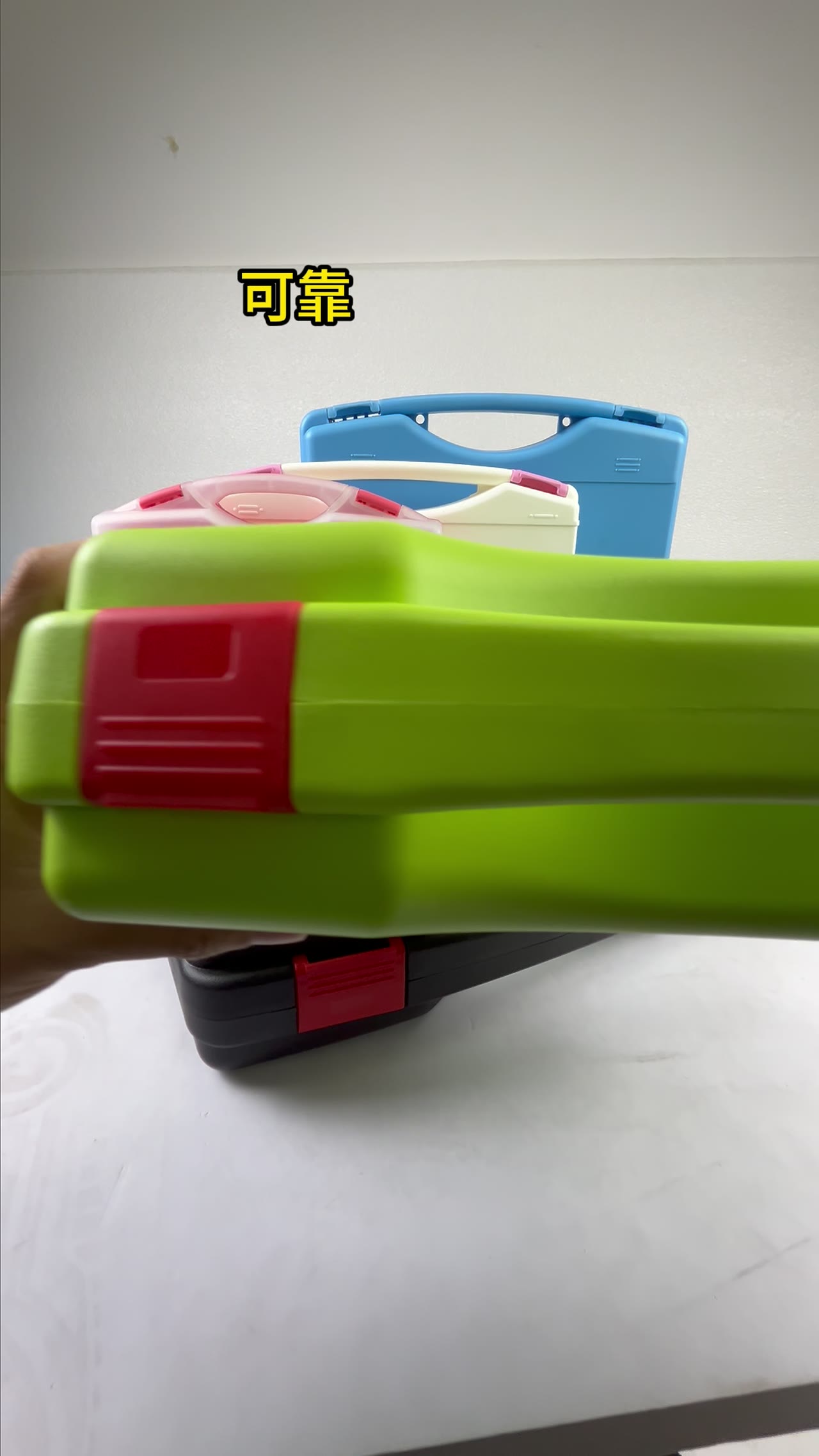
A lid this size stops behaving like a plate and starts behaving like a sheet stretched between whatever holds it. Double the span and the sag does not double, it multiplies by sixteen, which is why a case that feels rigid on the bench can dish in the middle once a machine is loaded and a second case goes on top. Extra wall thickness buys surprisingly little against that. The footage runs eighteen seconds and shows the shell from the outside; what follows is where the load actually travels inside it, and how a weak layout gets caught at the bench.
01Why the Lid Is Judged at L/300, Not by Feel
Bending goes with span to the fourth power and thickness cubed. Shorten a 600 mm span to 400 mm and centre sag falls to roughly a fifth; thicken a 4 mm wall to 6 mm and it only drops to a third. That asymmetry is the whole argument. This class is typically accepted at L/300, which is 2 mm of sag at 600 mm.
The figure marks where the gasket still seats and the latches still close by hand. Past it the lid lifts off the seal at the middle first, so a leak starts at the centre rather than the corners. Measure empty, latches engaged but untensioned, gauge on the centre, and subtract the 0.5 mm to 1 mm of moulded crown.
02Rib Pitch, Rib Direction, and Where the Latch Lands
Ribs usually sit at 80 mm to 150 mm centres. Wider than that and the panel between them behaves like a small simply supported plate and dishes anyway. Tighter than 80 mm and the mould gets crowded, melt reaches the rib root already cooling, and the weld line becomes a crack starter. Height runs 2.5 to 3 times wall, with a root fillet of at least 0.5 mm.
Direction follows the load. Stacking and centre pressure should be caught by ribs crossing the short side, then carried along the long side into the walls. Diagonal ribs read as stiff but dump force into the middle of a wall where nothing stands behind it. One rule gets missed: a latch has to land on a rib, or a few dozen cycles whitens the rim.
03Four Corner Supports Turn the Chassis Into a Beam
The usual mistake is supporting corners only. Four points make the equipment base a simply supported beam with its whole middle hanging, and the span is the full length of the unit. Sheet metal or thin-wall aluminium sags under its own mass plus road vibration; past 2 mm the feet lift off the foam and every impact runs into four points.
Four to six evenly spread supports is the working figure, no gap over 400 mm, and 300 mm on the heavy end. There is a shop test that needs no instrument: load the case, close it, then sight along the joint between base and foam from the side. A continuous bright line longer than 50 mm means a support is missing.
04Two-Person Carry and Three-High Stacking
Lifting with two people loads the wall under the handle, not the handle itself. Front and back rise together and the shell develops an upward moment at mid-span, which the rib beneath the handle must spread into both side walls. Put the handle anywhere else and a flat panel takes it. Out-of-step carriers make the case swing, and swing inertia runs about 1.5 times static load.
Stacking takes a different route. Three high, the bottom case carries the two above plus its own contents, with 200 kg to 400 kg the usual band at this size. Force arrives through the four edges of the upper base and lands on the rim and corners below, so the lid centre never sees it. Past three tiers, or above 60 kg each, add a board.
05Two Shop Checks and One Loading Rule
Two checks cover most of it. Press the lid centre with 50 kg through a 100 mm pad, hold one minute, keep deflection under 2 mm, and set under 0.3 mm after release. Set tells you more than peak: peak is elasticity, while set means a rib root has yielded or a weld line has opened.
The remaining rule concerns loading. With equipment installed, keep the centre of gravity within one third of the interior height above the base. Past that, a two-person carry tips forward, the lead carrier's wrist takes everything, and stairs become the failure mode. A tall load also rests its base edge on the lid instead of the wall.
| Panel deflection limit | ≤L/300 |
|---|---|
| Rib pitch | 80–150 mm |
| Rib height to wall ratio | 2.5–3.0 × wall |
| Support points | 4–6 evenly spread |
| Support span | ≤400 mm |
| Bottom case at 3-high stack | 200–400 kg |
| Lid centre load test | 50 kg, sag ≤2 mm |
| Permanent set after unload | ≤0.3 mm |
FAQ
Wouldn't a thicker lid be less prone to dishing?
Past about 5 mm the return is poor. Deflection runs with the cube of thickness, so 4 mm to 6 mm only brings it to a third, while cycle time and moulded-in stress rise and warp follows. Shortening the span from 600 mm to 400 mm takes it to a fifth for the cost of one rib.
Is a denser rib pattern always better?
No. Below 80 mm centres the melt is already cooling when it reaches the root, weld line strength drops, and cracks start there under load. Keep pitch between 80 mm and 150 mm and put a latch directly over a rib; that beats ten extra ribs.
Can thicker foam compensate for corner-only support?
It cannot. With four points the span is the full length of the unit, so thicker foam just raises the corners and leaves more of the middle hanging. Move to four to six spread points with no gap over 400 mm so every section of the base has somewhere to land.
Can a three-high stack become four?
It depends on unit weight. At three high the bottom case sees 200 kg to 400 kg typically; add a tier and it takes a full extra case, with rim and corners reaching their limit first. If you add one, put boards between tiers and recalculate lid sag.