

From Mould to Finished Case
A case is decided long before the first part drops out. Draft angle, mould temperature, cooling spread, ejection travel and flash are all baked into steel, and the first-off check is where you learn whether the tool behaves. What follows is what a moulder watches on that first shot and again at every service interval. A mould rarely fails overnight. It drifts a tenth of a millimetre at a time, and the drift always surfaces somewhere specific: draft pulls white at a corner, uneven cooling crowns the lid, a worn vent leaves flash on the joint.
01Cavity makes the outside, core makes the inside
The cavity side touches what the customer sees, so polishing and grain live there. The core forms the interior, where dimensional stability matters more than surface finish, so it can run rougher — but its vents must be generous. Gas trapped in a corner leaves a burn mark, and no amount of downstream polishing takes it out. The two halves usually differ in steel and heat treatment as well.
Draft is set per surface, not per part. A polished wall releases at 0.5–1°; a textured one needs 1.5–2°, and the deeper the grain the more it needs. Too little draft tears the wall white on ejection, most often at the corners. Too much and the rim flares, so lid and shell no longer line up at the joint. Most cases in this family sit between 0.5 and 2°.
02Mould at 40–80 ℃, hold water spread to 3 ℃
Mould temperature sets flow, shrinkage and surface replication at once. Run cold and the texture hazes over. Run hot and cooling time stretches, which costs cycle. Boxes of this size usually run somewhere in the 40–80 ℃ band, thin walls at the upper end and heavy sections lower, so inside and outside freeze at a similar rate rather than fighting each other.
Evenness beats the setpoint. Supply and return water should stay within 3 ℃, and the same applies side to side and top to bottom. A wide spread means one side shrinks first and the part bows: a lid face crowning 1–2 mm will not press flat, and the gasket loads unevenly. Flush the circuits every 8000 shots, since scale is the usual reason a spread creeps open.
03Ejector pins on ribs, 20–60 mm of travel
Ejector marks are the tool's fingerprints, and placement beats count. Pins belong on ribs, bosses and heavy sections, never on a seal groove, a parting face or a large visible panel. A 0.1 mm bump in a seal groove is enough to load the gasket unevenly, and water finds that segment first. Diameter follows load, commonly 3–8 mm, spaced 80–150 mm apart to spread the push.
A stroke of 20–60 mm is enough to break the part off the core; pushing further buys nothing. Short stroke means the robot grabs a case still gripping steel and pulls it out of shape. Long stroke wastes return time on the ejector plate. The real test is diagonal movement across the rim after ejection: past 1 mm, the push is uneven and the pin layout needs another look.
04Flash: 0.15 mm, measured at the parting face
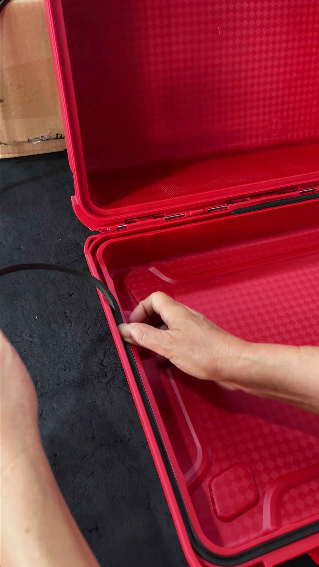
Flash comes from a parting face that does not seal: low clamp force, debris on the steel, a vent cut too deep. The line is 0.15 mm. Take eight points around the parting face with a calliper or a feeler gauge, and stop the press when it is crossed. Flash is not only ugly. It lifts the closing face, the lid cannot bottom out, gasket squeeze disappears and sealing degrades with latch force.
Trimming fixes looks, not dimensions. A hand-cut parting face leaves a 0.05–0.2 mm step, stacked cases no longer nest flat and they shift in transit. Flash has to be held inside the tool, not repaired downstream. Photograph the first-off parting face next to a rule every shift; when a dispute surfaces months later, the picture settles it faster than anyone's memory.
05Twelve first-off checks, 20–30 minutes, signed
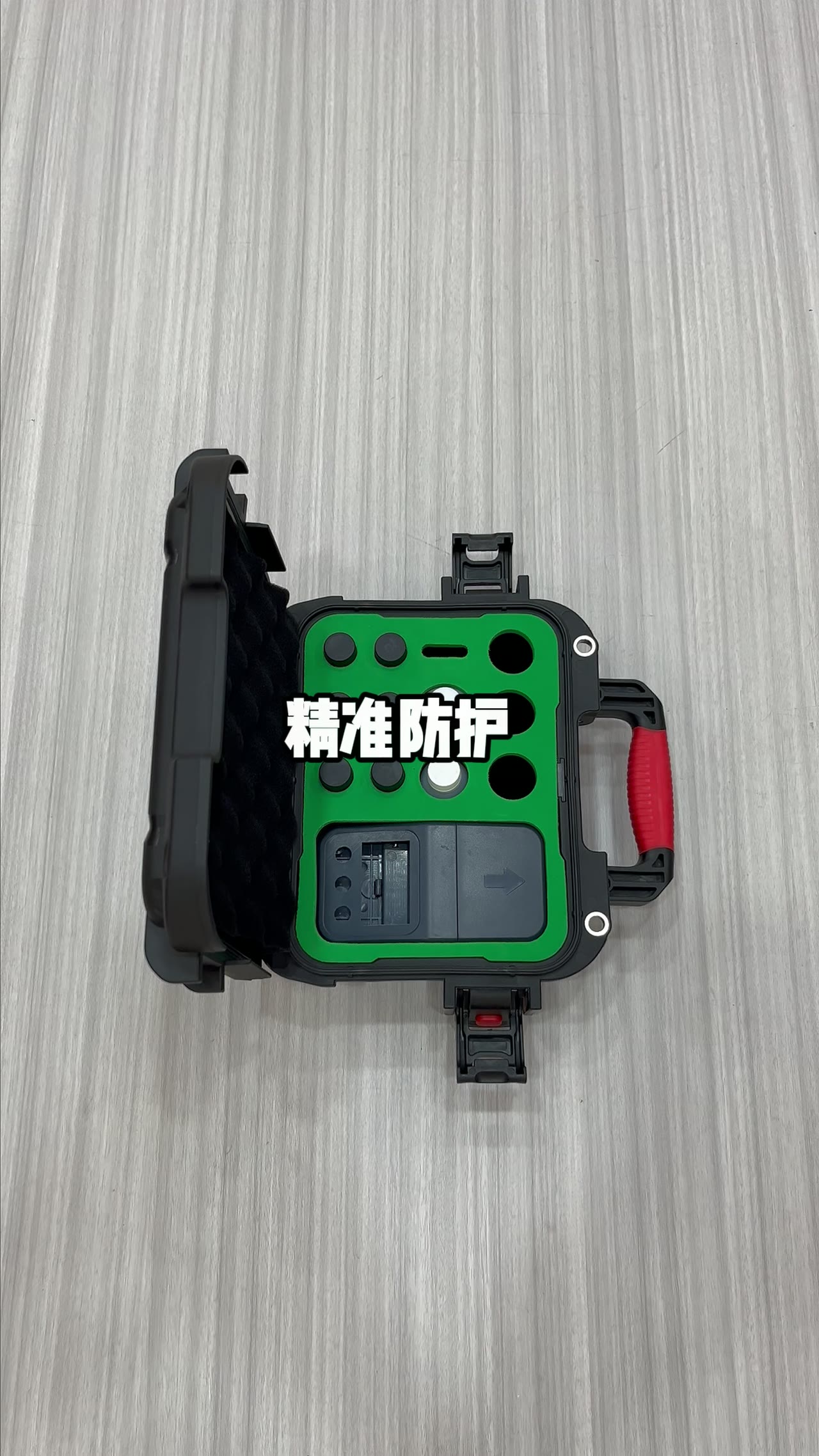
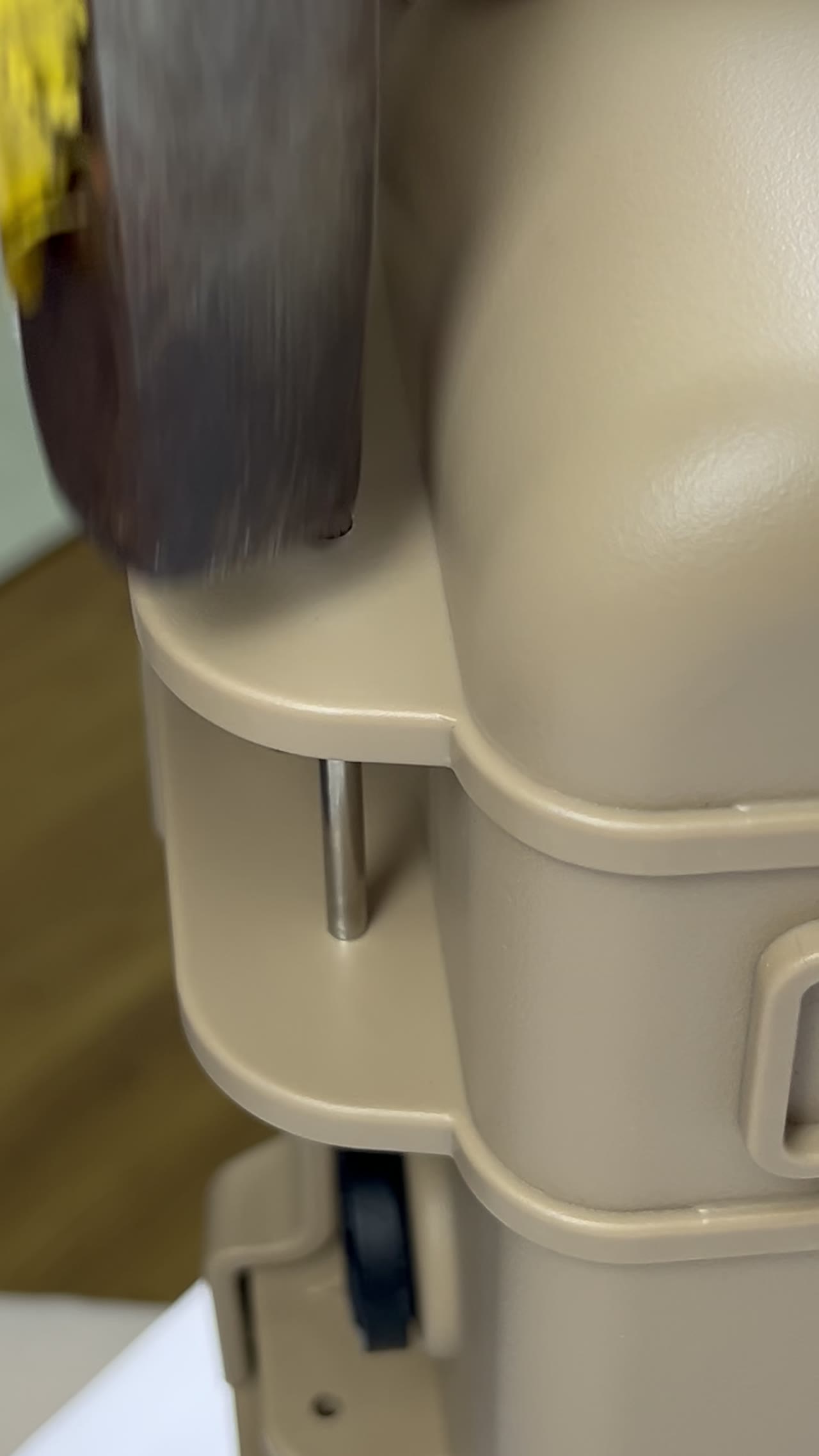
Sign-off is not a glance at colour. Twelve checks usually cover appearance, colour, wall thickness at three points, parting gap, lid flatness, latch force, hinge pin position, key internal dimensions, weight, flash, ejector marks and a trial close. Twenty to thirty minutes of measuring costs far less than reworking a batch. First-off pass rates typically land at 92–98%, with flash and colour taking most of the misses.
Service follows shot count, not the calendar. Every 5000–10000 shots: clean the vents, flush the circuits, grease pins and guides, inspect the parting face for peening. A tool that skips service does not fail at once. Flash grows from 0.1 to 0.2 mm, ejector marks deepen, and by the time it is visible to the eye several hundred parts have already shipped.
| Draft angle (polished / textured) | 0.5–2° |
|---|---|
| Mould temperature band | 40–80 ℃ |
| Cooling water supply-to-return spread | ≤3 ℃ |
| Ejection stroke | 20–60 mm |
| Allowed ejector-pin witness | ≤0.1 mm |
| Flash limit at the parting face | ≤0.15 mm |
| First-off checks / duration | 12 items, 20–30 min |
| Service interval | 5000–10000 shots |
FAQ
Can draft be a flat 2° everywhere to save drawing time?
It can, and the cost lands at the closing joint. More draft flares the rim, lid and shell stop lining up and the gap grows from 0.3 mm to over 1 mm. Give polished faces 0.5–1° and spend the flare budget on the sealing face instead.
Does a hotter mould not give a better surface?
Replication improves, but cooling time stretches and both cycle and internal stress get worse. Judge it on lid flatness: raise the setpoint one step, measure the lid face, and back off once crowning passes 1 mm. Appearance alone will mislead you.
Can you feel 0.15 mm of flash by hand?
No. That is roughly the thickness of two sheets of paper, essentially invisible to touch, yet enough to lift the closing face. Measure with a dial calliper or feeler gauge. Fingers and eyes generally only catch flash past 0.3 mm.
Where do the missing 2–8% of first-offs go?
Mostly back into the machine after adjustment, not into scrap. Very little reaches a production batch, split roughly evenly between flash and colour. So when a first-off fails, separate tooling faults from process faults first; tooling means pulling the mould.