

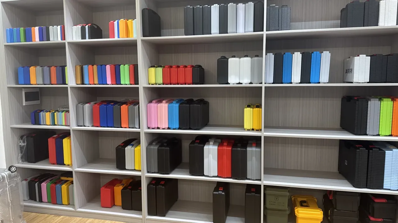
Quick answer: A Cable jointing & construction tool box sets an 18×12 mm base beam and 14 mm insert depth, holding 420 N for 10 min without pull-out.
Table of contents
- Base beam section of a Cable jointing & construction tool box
- Handle-insert depth and load transfer
- Insert displacement under a static pull
- Full-load deflection measured on the rig
- Beam wear after the cycling rig
- FAQ
1. Base beam section of a Cable jointing & construction tool box
A Cable jointing & construction tool box measures 580×410×250 mm outside and 515×350×185 mm inside, with 4.2 mm walls plus a rim flange. The base is ribbed into three beams of 18×12 mm section.
The 18×12 mm section is worked back from a 1.4 mm deflection limit at 15 kg. A 14 mm handle-insert depth lines up with the beam ends, so the 420 N static pull runs along the beam axis instead of tugging at one 4.2 mm wall. A Cable jointing & construction tool box draws both on one tool drawing, because changing either re-routes the load path.
| Static pull step | Hold time | Item checked |
|---|---|---|
| 140 N | 2 min | No visible insert movement |
| 280 N | 5 min | No beam-end cracking |
| 420 N | 10 min | No pull-out, no base collapse |
All three steps use one coupon, so readings share one datum.
2. Handle-insert depth and load transfer
On a Cable jointing & construction tool box the insert is set 14 mm deep, just past the 4.2 mm wall and into the beam ends; shallower, a 420 N pull lifts it with a ring of wall, deeper it breaks through the inner face.
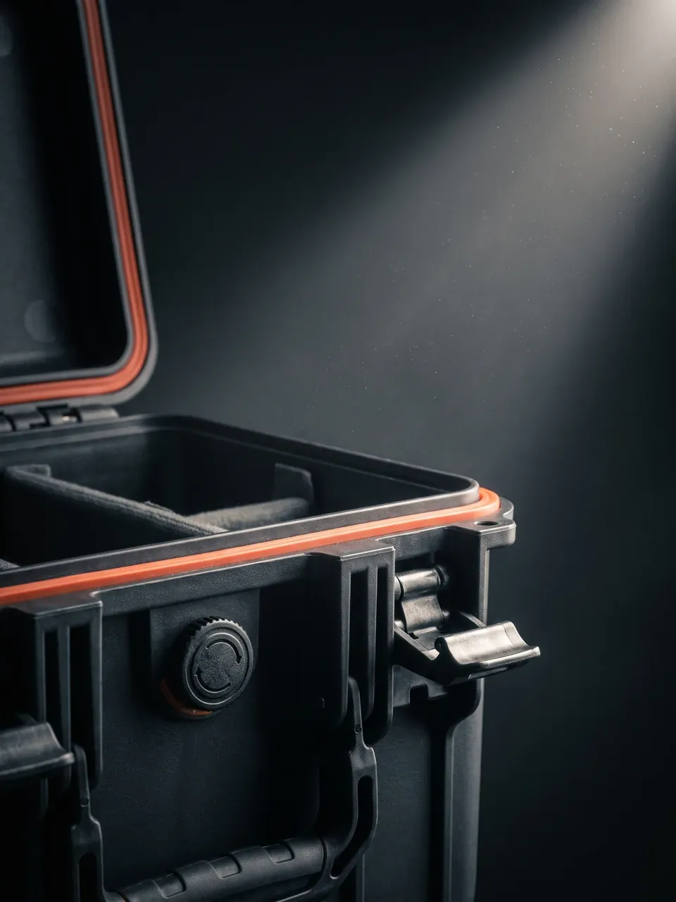
Insert to beam relies on the grip of a 14 mm embedment; beam to wall relies on the 18×12 mm section blending into the rim flange. Three beams run at equal pitch across the 515×350×185 mm cavity.
| Beam location | Section | Check condition |
|---|---|---|
| Middle beam | 18×12 mm | Aligned with the 14 mm insert |
| Outer beams | 18×12 mm | No end cracking at 420 N |
| Side wall return | Rounded blend | No warp at 15 kg |
3. Insert displacement under a static pull
The rig ramps 420 N in three steps and reads displacement after each hold. A Cable jointing & construction tool box takes 140 N for 2 min, 280 N for 5 min and 420 N for 10 min.
How the reading is taken matters more than the figure. A dial indicator sits on the insert top, a strain gauge on the beam end, a micrometer at the base centre, all timed together. The 280 N step must not jump in a staircase. At 420 N held 10 min the displacement curve has to flatten, and any continued climb counts as insert creep. A jump at 280 N usually points to a weld line around the insert, not to a 14 mm embedment too shallow. Records sit in three columns — static pull step, beam location, deflection reading — and share their numbering with the full-load rig. A Cable jointing & construction tool box ties the curve to the hold time so the result after 10 min repeats on a second rig.
The rim is benchmarked to IP66, two latches each rated 400 N, and the box still clamps after 3500 open-close cycles. Salt spray runs 72 h with no rust bloom on the insert.
4. Full-load deflection measured on the rig
A Cable jointing & construction tool box is loaded evenly across the cavity with the four corners shimmed flat; a micrometer at the base centre and two beam mid-spans reads zero empty, then deflects after 30 min at 15 kg. The reject line is 1.4 mm.
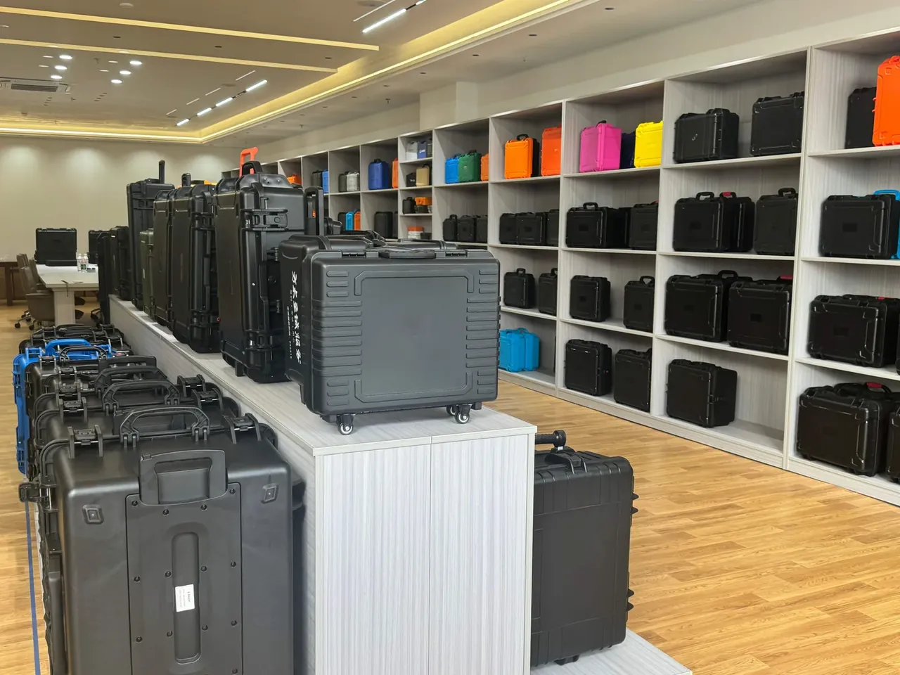
Mid-span is chosen over the edge because the wall props the edge and reads low by nature. Both the base centre and the middle beam mid-span must sit within 1.4 mm; reporting one alone proves nothing. A 1.0 m drop runs on the same batch before the full-load rig, drop first, because a grip face loosened by impact keeps sinking at 15 kg and the deflection curve lifts at once.
| Deflection reading | Measurement point | Verdict |
|---|---|---|
| ≤0.8 mm | Middle beam mid-span | Stiffness in reserve |
| 0.8 to 1.4 mm | Base centre | Inside the reject line |
| Over 1.4 mm | Any point | Reject |
5. Beam wear after the cycling rig
A Cable jointing & construction tool box ends the cycling rig by wiping the three beam seats, checking the 18×12 mm section for liner polish marks, then re-reading deflection at 15 kg. A gap over 0.2 mm is a wear reject.
Sampling takes three pieces per mould and measures the actual 14 mm insert depth and 18×12 mm section; if either drifts, the tool goes back. Salt spray 72 h, the IP66 benchmark, two latches at 400 N each, a 1.0 m drop and 3500 cycles sit in one lot record. When the 580×410×250 mm envelope, 6.0 kg empty weight and 15 kg load join the 420 N for 10 min sheet and the 1.4 mm deflection sheet, the lot of Cable jointing & construction tool box clears the shell-side checks.
Conclusion
A Cable jointing & construction tool box sets its load path with an 18×12 mm beam section and a 14 mm insert depth. The 420 N pull held 10 min governs insert retention, deflection within 1.4 mm at 15 kg governs the base, and a 1.0 m drop with 3500 cycles governs rebound after long load. Put those beside the 580×410×250 mm envelope and a whole lot has a basis for release.
Related Reading
- Divider layout in power cable accessory cases
- Handle structure of portable plastic tool boxes
- Base load capacity of hardware tool boxes
- Sealing grades for cable extrusion line cases
Related Products
- 8 Series — Gun Cases; Military Equipment Cases; Camera Equipment Cases; Drone Cases; Watch Cases; Knife Cases; First Aid Cases; Electronics Equipment Cases
- WL8-2812 PP Gun Case — model WL8-2812
- All protective cases and toolboxes: 7 series, 158 models