

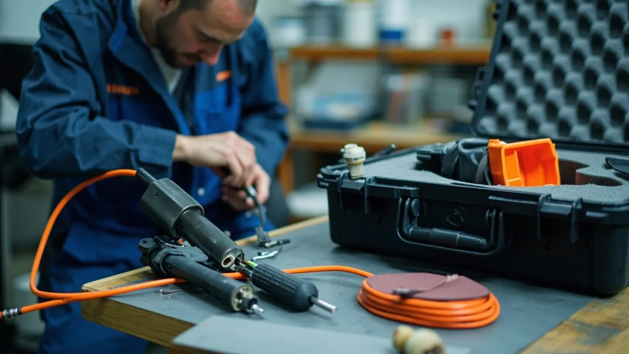
Cable accessories and line hardware share a common commercial profile: moderate volume, significant unit value, and severe consequences when they fail. Their transport protection problem is entirely different from that of transformers or switchgear. The silicone rubber pre-moulded parts, cold-shrink tubes and stress cones in cable accessories are elastic insulation components that fear compression set, ozone ageing, ultraviolet exposure and moisture pickup. Line hardware consists of metal load-bearing parts that fear thread damage, coating impact damage, fit surface corrosion and mixed parts. Compression terminals and connectors carry both characteristics at once, being vulnerable to oxidation and deformation simultaneously.
In practice these goods are frequently handled like generic hardware: woven sacks, cardboard boxes and loose wooden pallets. The result only becomes apparent at the construction site, when cold-shrink tubes are found with permanent indentations, stress cones have deformed and will not fit, preformed fittings are tangled, and impacted galvanised areas have already begun to show white rust. There is usually no remedy on site, only replacement, and cable accessory lead times are measured in weeks or months, so the schedule impact far exceeds the procurement cost.
This article is written for packaging, warehouse and logistics engineers at cable accessory plants, line hardware manufacturers, power engineering contractors, grid materials companies and overseas power EPC firms. It breaks down the protection requirements for cold-shrink and heat-shrink accessories, pre-moulded joints, cable terminations, compression fittings and overhead line hardware, and provides applicable packaging structures, material selection tables, cleanliness and moisture control schemes, and verification methods referencing the IEC 60502 series and ISTA. The core conclusion is that the leading requirement for a cable accessory case is shape retention and cleanliness, while the leading requirement for a line hardware case is impact protection and mixed-parts prevention. The two speak different packaging languages and cannot share one standard.
For power materials packaging programmes, JUNZHJIA (Kexin New Materials (Guangdong) Co., Ltd.) typically uses a combination of category separation, compartmented inserts and barrier sealing, treating electrical accessories and line hardware as separate flows while lowering overall packaging investment through common case shells with replaceable inserts.
Table of Contents
- 1. Transport Risks for Cable Accessories and Line Fittings: Cleanliness, Moisture and Shape
- 2. Cold-Shrink and Heat-Shrink Accessory Cases: Storage Life, Light and Ozone
- 3. Prefabricated Joint and Silicone Component Cases: Holding the Stress Cone Shape
- 4. Cable Terminations and GIS Termination Assemblies
- 5. Terminals, Connectors and Compression Fittings
- 6. Line Hardware Cases: Suspension Clamps, Tension Clamps and Link Fittings
- 7. Preformed Fittings, Vibration Dampers and Spacers
- 8. Grounding Boxes, Cross-Bonding Boxes and Sheath Protectors
- 9. Cleanliness and Moisture Control
- 10. Vibration, Compression and Stacking: Differentiated Design for Long and Heavy Items
- 11. Sealing and Ingress Protection: IP65, IP67 and Pressure Equalisation
- 12. Case Construction and Insert Selection
- 13. Lifting, Stacking and Transport Markings
- 14. Test Verification and Procurement Acceptance
- Frequently Asked Questions
- Conclusion & Related Reading
1. Transport Risks for Cable Accessories and Line Fittings: Cleanliness, Moisture and Shape
Understanding the packaging logic for this material family starts with three red lines.
The first red line is cleanliness. The insulation interfaces of cable accessories, such as the inside of a cold-shrink tube, the bore of a pre-moulded part and the inner surface of a stress cone, sit directly against the cable insulation surface after installation. No particle, oil film or moisture is permitted between them. Any contamination concentrates the local electric field and, over long-term operation, leads to partial discharge and eventually breakdown. Such contamination is usually invisible at unpacking, which makes the consequence long-term rather than immediate. Accessory packaging must therefore be clean-grade: inserts must not shed particles, materials that release oily volatiles must be avoided, and interfaces need protective caps or barrier bags.
The second red line is moisture. Silicone and EPDM rubber are hydrophobic, but fillers and interface treatment agents can absorb moisture. Metal conductive surfaces in copper and aluminium oxidise in damp conditions, and the oxide layer raises contact resistance significantly. Paper insulation and semi-conductive tape fail directly through moisture pickup. Compounding the problem, many accessories are stored on site in open yards or unroofed warehouses, so the moisture resistance of the packaging directly determines installation quality.
The third red line is shape retention. Silicone pre-moulded parts, cold-shrink tubes and stress cones take a permanent set after prolonged compression. Once set, they cannot recover their original interface pressure, and both sealing and electrical performance decline. This red line is the easiest to overlook, because nothing appears to happen during transport; the part was merely compressed for several months.
| Material class | Typical items | Dominant failure mode | Protection priority | Key control |
|---|---|---|---|---|
| --- | --- | --- | --- | --- |
| Cold-shrink accessories | Cold-shrink tube, termination, straight joint | Permanent indentation, support strip displacement, bore contamination | Shape retention > cleanliness > moisture | No compression, upright or specified attitude |
| Heat-shrink accessories | Heat-shrink tube, termination, sealing tape | Surface scratching, adhesive blocking, moisture | Cleanliness and moisture | Segregated storage, heat avoidance |
| Pre-moulded joints | Silicone pre-moulded part, stress cone, insulation cylinder | Deformation, bore scratching, ageing | Shape retention > cleanliness | Independent support, light and ozone exclusion |
| Cable terminations | Outdoor terminal, GIS terminal, bushing assembly | Porcelain or composite damage, oil or gas state anomaly | Impact and moisture | Profiled insert, interface protective covers |
| Compression fittings | Terminal lug, connector, bimetallic transition | Conductive surface oxidation, compression zone deformation | Cleanliness and impact | Protective caps, compartments, desiccant |
| Line hardware | Suspension clamp, tension clamp, clevis, ball eye | Thread damage, galvanised coating impact damage, mixed parts | Impact and parts separation | Compartmented trays, individual marking |
| Preformed fittings | Preformed rods, vibration damper, spacer | Rod deformation, rubber ageing | Shape retention and impact | Shape-retaining ties, separate cavities |
2. Cold-Shrink and Heat-Shrink Accessory Cases: Storage Life, Light and Ozone
Cold-shrink accessories and heat-shrink accessories are the two highest-volume families in cable work, and their packaging requirements differ noticeably.
The governing constraint for cold-shrink parts is that they must not be compressed. At manufacture, a cold-shrink tube is held expanded by an internal support strip, and interface pressure comes from the elastic recovery of the rubber. If it is crushed, folded or left in contact with a hard object for a prolonged period during transport or storage, the rubber takes a permanent set, recovery force drops, and interface pressure after installation is insufficient. Over time this can produce surface tracking or moisture ingress. Design points for cold-shrink packaging:
- Independent support, no stacking load. Each tube sits in its own semicircular channel sized slightly larger than the finished outside diameter, so the tube contacts only along a line rather than over an area.
- No folding. Long tubes should lie along the long axis of the case. If the case is too short, use a longer case; never bend the tube to fit.
- The support strip must not shift. If the internal support strip slides out, the tube contracts prematurely and is scrapped, so end restraint is required inside the case.
- Exclude light and heat. Rubber parts must not be exposed to prolonged direct sunlight or high temperature. The case should be opaque, and storage temperature should not exceed about 35 degrees Celsius.
Heat-shrink parts tolerate more abuse but still need two things: avoidance of contact with sharp edges that scratch the surface, and control of storage temperature, because the adhesive layer on a heat-shrink tube blocks at high temperature. Heat-shrink materials soften near their service temperature, and long storage close to the softening point accelerates ageing, so packaging should state the maximum storage temperature.
Storage-life management is part of packaging design. Silicone and EPDM parts carry recommended storage periods, commonly two to three years from the date of manufacture unless the manufacturer specifies otherwise. Packaging should clearly state the manufacturing date, batch number and storage period, and parts past the period should be marked as requiring inspection before use. Printing this information on both the case and the inner packaging is the lowest-cost quality management measure available.
For accessories shipped overseas by sea, sealing each part in an aluminium-foil barrier bag with desiccant and humidity indicator cards is advisable. Material pairing is covered in case foam material comparison and selection.
3. Prefabricated Joint and Silicone Component Cases: Holding the Stress Cone Shape
Prefabricated joints, including silicone pre-moulded parts, stress cones, insulation cylinders and shielding shells, are the highest-value and most shape-sensitive cable accessories.
The bore and inner surfaces of a stress cone or pre-moulded part are functional surfaces. Bore dimensions and inner surface roughness determine interface pressure and field distribution. Any scratch, indentation or oil film becomes an initiation point for partial discharge after commissioning. Insert design requirements follow:
- The bore must not contact any hard material. Insert a single-use protective core in soft PE or paper and close both ends with soft plugs.
- Use semi-encapsulation externally. The part should be cradled rather than pressed, avoiding compression set in the rubber.
- Provide separate cavities. Do not ship in the same cavity as metal hardware or bolts.
- Exclude light and ozone. Silicone rubber is sensitive to ozone and ultraviolet, so the case should be opaque, and long-term storage alongside ozone-generating equipment such as motors and transformers must be avoided.
Metal parts such as shielding shells, springs and clamps should be packed separately and must never touch silicone components directly. Hard metal edges are the primary cause of rubber scratching.
Mixed specifications are the most common source of field problems. One project often uses pre-moulded parts of several cross-sections and voltage classes, and mixing them up leads to incorrect installation. Use a compartmented insert, one part per compartment, with a label in each compartment and a packing list plus specification cross-reference table inside the lid. Removable divider systems offer high value here, and the design approach is described in removable divider systems for protective cases. The standard practice in cable accessory case programmes at JUNZHJIA is a common outer case with specification-specific compartmented trays, so the customer can change inserts without changing cases when projects change.
4. Cable Terminations and GIS Termination Assemblies
Cable terminations, whether outdoor, indoor or GIS type, combine a porcelain or composite housing, internal insulation and a metal flange. Their protection logic closely mirrors transformer bushings, but at smaller scale and higher quantity.
Outdoor terminations and composite housings are most at risk from impact on the porcelain or composite sheds. The case should provide shed relief pockets at least 1.1 times the shed outside diameter in depth, and should use the flange or mounting base as the primary load-bearing surface so no shed carries load. Composite silicone-shed terminations additionally must not be compressed for long periods, to avoid deformation at the shed root.
GIS terminations include SF6 compartment interfaces and density monitors. Transport should follow the manufacturer's instruction on whether the compartment is charged, and interface flanges must have protective covers. The density monitor is a precision part and should have its own vibration-isolated packaging rather than sharing a cushioning cavity with the termination body.
Oil-filled terminations require attention to oil level attitude and seal condition. The case should carry an upright-transport marking plus axial restraint, and all oil ports must be plugged. For long ocean voyages, charging the case with dry air or nitrogen at slight positive pressure with a pressure recording label allows the reading to be compared on arrival.
For porcelain terminations, the impact resistance of the case is the priority. Cushioning design should derive insert thickness from the allowable acceleration of the brittle features, typically controlled between 0.5 g and 1.0 g, together with the natural resonant frequency, rather than adding foam by intuition.
5. Terminals, Connectors and Compression Fittings
Terminal lugs, connectors, bimetallic transition pieces and compression-type fittings combine high-precision conductive surfaces, soft materials such as copper and aluminium, and large batch quantities.
Oxidation of conductive surfaces is the primary risk. Copper and aluminium form oxide films quickly in humid air; copper darkens and can blacken, while aluminium forms a dense aluminium oxide layer. The oxide layer raises contact resistance substantially and causes heating under high current. Countermeasures include protective caps or neutral protective film on conductive surfaces, desiccant inside the case, vapour phase corrosion inhibitor packaging, and avoidance of packaging materials containing sulphur or chlorine.
Deformation of the compression zone is a secondary but common risk. The compression zone of a lug or connector must be a regular cylinder or hexagon. If it is crushed in transport, the compression die cannot close correctly and crimp quality cannot be guaranteed. Provide compartments inside the case so that large parts do not press on small ones and heavy parts do not press on light ones.
Mixed parts risk should not be underestimated. Terminal lugs come in many sizes covering conductor cross-section, bolt hole spacing and material, and once mixed, rework on site is the only option. Use compartmented trays with individual labelling and a cross-reference table inside the lid. For bimetallic transition pieces, which are easily confused with plain copper parts, use a different label colour.
For volume supply of compression fittings, a two-piece insert of compartmented tray plus lid compression pad works well, combining handling efficiency with freedom from movement in transit. Insert design thinking is covered in custom foam insert design guide.
6. Line Hardware Cases: Suspension Clamps, Tension Clamps and Link Fittings
Overhead line hardware, including suspension clamps, tension clamps, clevis plates, ball eyes, U-shackles, yoke plates and link plates, consists of load-bearing metal parts that appear indestructible yet generate three recurring problems in transport: thread damage, galvanised coating impact damage and mixed parts.
Thread damage is the most common. Once a bolt, pin or threaded section is struck, threading a pin or tightening on site is obstructed, and in severe cases field filing is required, which destroys the galvanised coating. Countermeasures include plastic thread protection caps, bagging bolts and pins individually, and compartmented trays so parts cannot strike each other.
Galvanised coating impact damage directly reduces corrosion protection. A hot-dip galvanised coating loses its protective function where it is struck, and the sacrificial action of zinc only covers a small exposed area. In humid and coastal environments, white rust appears at the damaged spot quickly. Control measures include compartments and layering, heavy parts below and light parts above, soft interleaves between parts, and no free bulk stacking inside the case.
Mixed parts are especially serious for hardware, because clevis plates and ball eyes of different ratings look similar but carry very different loads. Using the wrong one creates a genuine safety hazard. Control measures include compartments by model, a label in each compartment showing model, material and batch, a packing list with illustrations inside the lid, and individual marking of critical load-bearing parts.
One point matters especially for hardware case stacking: hardware is dense and individual case weight is high, so the load on the bottom case during stacking can greatly exceed expectations. Design should calculate load from measured case weight and stacking layers, and verify it by physical stacking test. Method details are covered in GB/T 4857 transport packaging test methods explained.
7. Preformed Fittings, Vibration Dampers and Spacers
Preformed fittings, including preformed rods, preformed tension clamps and preformed suspension clamps, vibration dampers and spacers are the category where geometry determines performance.
The failure mode of preformed rods is deformation of the helical set. A preformed rod assembly is made of multiple helically formed metal wires, and once it is bent, crushed or tangled, it cannot be wrapped correctly on site. Packaging requirements include keeping the factory shape-retaining ties in place, fixing each group with a shape-retaining clamp, providing elongated channels so the rods stay straight or in their natural curve, and absolutely avoiding 180 degree folds.
Vibration dampers consist of heads, a stranded steel cable and a clamp, and the relative position of the head determines the frequency response. If a head shifts in transport, damping performance falls and cannot be corrected on site. Provide head restraint inside the case, and never suspend the damper by the stranded cable alone.
Spacers, including damping and jumper spacers, contain rubber or elastic elements and are thus metal plus rubber assemblies. The rubber elements also take a permanent set under compression, so the packaging must satisfy metal impact protection and rubber compression protection at the same time. Use separate cavities with relief at the rubber elements.
All three share large batch quantities, moderate unit value and high mixed-parts risk, which means the design value of compartments and labelling exceeds the value of cushioning design. When using compartmented trays, size the compartment count to project consumption, for example an integer multiple of the fittings required per conductor span, so that site crews can take a full compartment rather than counting individual pieces.
8. Grounding Boxes, Cross-Bonding Boxes and Sheath Protectors
Grounding boxes, cross-bonding boxes and sheath protectors are ancillary equipment in high-voltage cable systems, typically containing copper busbars, connection terminals, sheath protectors using non-linear resistors or spark gaps, and a sealed enclosure.
Enclosure sealing is critical during transport and storage. These devices are designed for outdoor installation and carry a degree of ingress protection, but impact in transit can distort the enclosure or damage a sealing face, requiring repair before commissioning. Packaging design should treat the enclosure as a precision item: primary support at the mounting base, lateral restraint at the sides, and no torsional load on the shell.
Sheath protectors are electrical components sensitive to moisture. Seal them in barrier bags with desiccant and humidity indicator cards, and avoid severe vibration in transport to prevent displacement of the internal non-linear resistor discs.
Busbars and terminals are protected in the same way as compression fittings: protective caps to prevent oxidation and impact damage.
For this device-plus-accessory combination, use a structure of separate main case, separate accessory bags and common containment: the main item in the primary cavity, and accessories such as bolts, gaskets and installation instructions in a dedicated compartment inside the lid, so that mating parts are never missing on site.
9. Cleanliness and Moisture Control
Cleanliness and moisture control for cable accessories and hardware can be implemented at three levels.
Level one: interface protection. Functional interfaces such as bores, inner surfaces and sealing faces require physical isolation rather than mere wrapping. Use a protective core plus plug plus barrier bag. Barrier bag material should be clean-grade, and the interface must be confirmed free of oil and particles before sealing.
Level two: in-case humidity control. Use an aluminium-foil barrier bag with desiccant and humidity indicator cards. Charge desiccant at the engineering rule of thumb of 0.5 to 1.0 kg of silica gel per cubic metre of free volume, and place at least three reversible indicator cards inside the bag. Case sealing should be at least IP65, and for ocean freight IP67 with a pressure equalisation valve is recommended to eliminate the moisture ingress caused by the breathing effect, described in how a protective case pressure equalisation valve works.
Level three: corrosion protection for metal surfaces. Copper and aluminium conductive surfaces and galvanised parts need neutral protective film, vapour phase corrosion inhibitor paper or anti-rust grease. Compatibility matters: VCI volatiles can deposit on silicone rubber surfaces, so VCI materials should not share a cavity with rubber components; use separate cavities or separate cases.
One practical detail deserves emphasis: accessory installation usually happens outdoors or in a semi-sheltered area, and protection ends the moment the packaging is opened. Packaging design should therefore support re-sealing. Barrier bags should be resealable, desiccant should be a replaceable module, and the case should be re-openable without destroying the gasket. These features substantially reduce rework risk at the construction site.
10. Vibration, Compression and Stacking: Differentiated Design for Long and Heavy Items
Cable materials span an extreme range of shapes: multi-metre terminations and preformed rods at one end, and 50 kg tension clamps and clevis plates at the other. Packaging must be tiered by shape and mass.
Long items such as terminations, preformed rods and cold-shrink tubes require axial restraint and bending prevention. The case needs sufficient longitudinal stiffness, which means a steel frame or a rotational-moulded case with reinforcing ribs, end stops at both ends, and intermediate supports at intervals not exceeding 800 mm. Supporting only the two ends and leaving the middle unsupported is unacceptable: the case must provide support along the full length.
Heavy items such as tension clamps, clevis plates and anchors require load distribution and impact prevention. Use a continuous rigid base under the case, and provide an individual bearing pad under each part in the insert so that concentrated stress cannot collapse the case floor. Stacking strength should be calculated from actual case weight and layer count and verified physically.
For mixed loading in one case, follow heavy below and light above, with hard and soft separated: metal parts at the bottom, rubber and insulation parts in the upper layer or in separate cavities, and no part with sharp edges adjacent to a rubber component.
On vibration design, the allowable acceleration for cable accessories is generally more generous than for porcelain, but they remain sensitive to micro-movement during long storage, particularly at pre-moulded interfaces. Cushioning should therefore target resonance suppression rather than thickness: keep foam static stress below 60 percent of the stress at 25 percent compression to avoid creep, and layer two foam densities to widen the damping band. For mixed cases spanning a wide range of mass and shape, size the support structure from the heaviest item first, then size the cushioning layer from the lightest, designing the two separately. Methods and pass criteria are covered in how to select and run ISTA transport testing procedures.
11. Sealing and Ingress Protection: IP65, IP67 and Pressure Equalisation
Under IEC 60529 and GB/T 4208, the selection logic for cable material cases is as follows.
| Rating | Dust | Water | Typical application | Notes |
|---|---|---|---|---|
| --- | --- | --- | --- | --- |
| IP54 | Partial dust protection | Splash resistant | In-plant movement, covered warehouse | Short-term use only |
| IP65 | Dust tight | Water jet resistant | Domestic road transport, general warehousing | Common baseline for accessory cases |
| IP67 | Dust tight | Temporary immersion, 1 m for 30 min | Ocean freight, open storage yards, coastal projects | Use with a pressure equalisation valve |
| IP67 plus valve | Dust tight | Immersion plus differential pressure equalisation | Long trans-climate ocean shipments | Best overall protection |
Three reminders. First, an IP rating does not cover cleanliness; an IP67 case with a shedding insert still carries interface contamination risk. Second, an IP rating does not cover shape retention of rubber parts, because the pressure comes from stacking inside the case rather than from outside water and dust. Third, large-volume cases in long-term storage should have a pressure equalisation valve, because silicone parts are often stored for years and full sealing amplifies the breathing effect that draws external moisture in as the case cools. Structural and verification details for IP67 are covered in IP67 protective cases: structure, sealing and verification. Gasket material must tolerate the extreme temperatures at the project location, and silicone or EPDM should be specified for severe cold, as described in protective case design for extreme temperature environments.
12. Case Construction and Insert Selection
Case construction for cable materials is tiered by shape and mass.
| Tier | Typical items | Recommended construction | Insert approach | Key requirement |
|---|---|---|---|---|
| --- | --- | --- | --- | --- |
| Precision rubber parts | Cold-shrink tubes, pre-moulded parts, stress cones | Injection or rotational-moulded case | Semicircular channels or separate-cavity tray | No compression, opaque, clean foam |
| Medium to long items | Cable terminations, preformed rods | Steel frame or reinforced rotational-moulded case | Elongated channels plus end stops | Full-length support, no folding, axial restraint |
| Compression fittings | Lugs, connectors, transitions | Rotational-moulded case | Compartmented tray plus lid compression pad | Protective caps, compartments, desiccant |
| Heavy hardware | Tension clamps, clevis plates, ball eyes | Rotational-moulded case with steel base | Individual bearing pads plus compartments | Continuous base, verified stacking strength |
| Ancillary equipment | Grounding boxes, cross-bonding boxes | Rotational-moulded or frame case | Primary cavity plus accessory compartments | Base primary support, lateral restraint |
Insert material selection follows the same differentiated logic:
| Material | Density (kg/m3) | Characteristics | Typical use |
|---|---|---|---|
| --- | --- | --- | --- |
| Closed-cell EVA | 60-120 | High resilience, dimensionally stable, precision machinable | Rubber part channels, compartmented trays |
| Closed-cell PE | 25-70 | Good energy absorption, low cost | Bearing pads for heavy parts, end buffers |
| PU foam | 20-60 | Good damping | Precision parts needing resonance suppression |
| EPP moulded parts | 30-60 | Excellent resilience, complex geometry | Volume-production compartmented trays |
| Laminated assemblies | Varies | Stiffness designed in stages | Graded support for long items |
On manufacturing process, injection-moulded PP or ABS suits small and medium parts needing tight insert fits, rotational-moulded HDPE suits medium and large or heavy items, and steel frame cases suit long items and very heavy parts. Whichever process is chosen, hinges, latches and gaskets should be replaceable to support long service life and spare-part supply, as described in toolbox hinge, latch and gasket structure explained and case foam material comparison and selection.
13. Lifting, Stacking and Transport Markings
Cable material cases require one marking group that other industries do not: storage conditions and storage life.
Six marking groups:
- Product name, model and specification, quantity and batch number, marked on both the outer case and the inner compartments.
- Manufacturing date and recommended storage period.
- Storage conditions covering maximum temperature, light exclusion and ozone exclusion.
- Centre of gravity and lifting points for heavy cases.
- Permitted stacking layers, or a no-stacking instruction, which is typical for rubber part cases.
- Handling symbols to GB/T 191 for keep-dry, this-side-up, fragile and do-not-roll.
Four operating rules:
- Rubber part cases must not be stacked, or must be stacked strictly to the marked layer count.
- Long items must lie flat along the case axis; leaning against a wall or spanning unsupported is prohibited.
- Never lift a case using the product itself as a lifting point.
- Cases stored outdoors should be checked periodically for gasket condition and for the humidity indicator readings.
The value of marking is that it turns an implicit storage-life requirement into an explicit constraint. In engineering practice, reduced rubber performance from over-long storage usually occurs without any visible anomaly on site.
14. Test Verification and Procurement Acceptance
The product performance of cable accessories is governed by the IEC 60502 series, in which IEC 60502-4 specifies test requirements for accessories for extruded insulation power cables rated above 1 kV up to 30 kV, with higher voltages referencing IEC 62067. The equivalent domestic framework is the GB/T 12706 series. Those standards address the electrical and mechanical performance tests of the accessory itself, while packaging and transport verification normally references the ISTA and GB/T 4857 series.
One clarification is essential: type tests in a product standard cannot replace packaging and transport verification, and the reverse is equally true. The objective of packaging verification is to demonstrate that after transport, the accessory still meets its factory performance requirements, so post-test re-inspection must map to the accessory's critical performance characteristics.
Recommended transport packaging verification items:
| Test | Reference | Typical condition (example) | Pass criteria |
|---|---|---|---|
| --- | --- | --- | --- |
| Random vibration | ISTA 3E / GB/T 4857.23 | Road spectrum, 60-120 min | No displacement, no permanent rubber indentation, no interface contamination |
| Drop and shock | ISTA 2A / GB/T 4857.5 | Height by weight class | No through-wall damage, no hardware deformation or coating damage |
| Stacking | GB/T 4857.3 | Specified load, 24 h or more | Case deformation recovers, no compression set in bottom-layer items |
| Dust and water ingress | IEC 60529 / GB/T 4208 | IP65 / IP67 | No dust ingress, no harmful water entry |
| Temperature and humidity cycling | IEC 60721-3 climate classes | High-temperature and humidity cycling | No condensation, no metal corrosion, indicator cards unchanged |
| Salt spray for ocean or coastal use | Neutral salt spray test | 48-96 h | No red rust or white rust on hardware and galvanised parts |
| Environmental methods (reference) | MIL-STD-810H methods | Vibration, shock, humidity | Methodology reference only, not a military certification |
Citations of MIL-STD-810H must be worded accurately: the standard is used here as a source of environmental test methodology, for example Method 514 vibration, Method 516 shock and Method 507 humidity, and does not represent any military certification of the product. Correct wording is explained in MIL-STD-810H and protective case environmental testing.
Procurement acceptance should use three sampling categories. Variable inspection applies to critical dimensions and structure, including insert channel dimensions, protective core fit, gasket compression ratio and base stiffness. Attribute inspection applies to appearance and marking, including coating condition, label content and packing list completeness. Batch-level type verification applies to material and performance items such as foam density and UL94 flammability grade, case material and desiccant charge quantity. The sampling logic can follow GB/T 2828.1, with a worked approach in custom case acceptance and AQL sampling methods.
The documentation package should include material certificates covering case material, foam density and flammability grade, gasket material and hardness, ingress protection self-test or third-party reports, vibration, drop and stacking test reports, a packing work instruction, a packing list with cross-reference table, and a storage maintenance procedure. For power materials packaging programmes, JUNZHJIA can supply this documentation against a customer acceptance checklist and coordinate third-party inspection on a sampling basis.
Frequently Asked Questions
Q: Why must cold-shrink cable accessories not be stacked, and what is the correct packaging approach?
A: Cold-shrink accessories rely on the elastic recovery of rubber to generate interface pressure. A cold-shrink tube leaves the factory held expanded by an internal support strip; during installation the strip is pulled out, the tube contracts onto the cable insulation surface, and that contraction creates both the seal and the electrical interface. If the tube is crushed, folded or left against a hard object for a long period during transport or storage, the silicone or EPDM rubber takes a compression set, recovery force falls, interface pressure after installation is insufficient, and long-term operation can produce surface tracking or moisture-induced breakdown. Correct packaging has four elements. Each tube sits in its own semicircular channel sized slightly larger than the finished outside diameter, so contact is along a line rather than across an area. Tubes lie straight along the long axis of the case, folding is prohibited, and if the case is too short a longer case must be used rather than bending the product. End restraint prevents the internal support strip from shifting, because once it slides out the tube contracts prematurely and is scrapped. Finally, exclude light and heat: use an opaque case, keep storage below about 35 degrees Celsius, and mark the manufacturing date and recommended storage period on the packaging.
Q: What matters most in protecting pre-moulded cable joints such as stress cones?
A: Protecting the bore, which is a functional surface, while preventing compression set in the rubber. Bore dimensions and inner surface roughness determine both interface pressure and electric field distribution, and any scratch, indentation or oil film can become a partial discharge initiation point after commissioning. The practical measures are these. Insert a single-use protective core in soft PE or paper into the bore and close both ends with soft plugs, creating physical isolation rather than relying on outer packaging alone. Use semi-encapsulating support externally so the part is cradled rather than pressed, avoiding compression set. Provide a separate cavity and never ship in the same cavity as metal hardware or bolts, because hard metal edges are the main cause of rubber scratching. Exclude light and ozone by using an opaque case, and avoid long-term storage alongside ozone-generating equipment. In addition, mixed specifications are the main cause of incorrect installation on site, so use a compartmented insert with one part per compartment, a label in each compartment, and a packing list plus specification cross-reference table inside the lid.
Q: What problems are most common in line hardware transport, and how does packaging prevent them?
A: Three problems dominate. The first is thread damage: once a bolt, pin or threaded section is struck, threading a pin or tightening on site is obstructed, and in severe cases field filing is needed, which destroys the galvanised coating. Countermeasures include plastic thread protection caps, bagging bolts and pins individually, and compartmented trays so parts cannot strike each other. The second is impact damage to the galvanised coating, which loses its protective function at the damaged spot and develops white rust quickly in humid or coastal conditions; control this through compartments and layering, heavy parts below and light parts above, soft interleaves between parts, and no free bulk stacking. The third is mixed parts: clevis plates and ball eyes of different ratings look similar but carry very different loads, and mixing them is a genuine safety hazard, so compartment by model, label every compartment with model, material and batch, include a packing list with illustrations inside the lid, and mark critical load-bearing parts individually. Because hardware is dense and case weight is high, stacking strength must also be calculated from measured weight and layer count and verified by physical test.
Q: Why do preformed fittings and vibration dampers have such strict shape requirements?
A: Because their performance depends directly on geometry. A preformed rod assembly consists of multiple helically formed wires set to shape at manufacture, and once it is bent, folded 180 degrees or left tangled in transport, it cannot be wrapped correctly on site and cannot be restored by straightening. A vibration damper consists of heads, a stranded steel cable and a clamp, and the relative position of the head and cable determines its natural frequency and damping behaviour; if a head shifts in transport, damping performance drops and there is no field correction. Spacers, including damping and jumper types, contain rubber or elastic elements that also take a compression set under load. The packaging requirements follow: keep factory shape-retaining ties in place, fix each group with a shape-retaining clamp, provide elongated channels so rods stay straight or in their natural curve, restrain the damper heads, never suspend a damper by its stranded cable alone, and use separate cavities with relief at rubber elements for spacers. These items ship in large batches with high mixed-parts risk, so the design value of compartments and labelling usually exceeds that of cushioning.
Q: How is the cleanliness requirement for cable accessory cases implemented in practice?
A: Cleanliness must be implemented across materials, structure and working practice. On materials, use clean-grade foam that does not shed particles and does not release oily volatiles, avoid plain EPS foam, and use clean-grade barrier bag material. On structure, functional interfaces such as bores, inner surfaces and sealing faces require physical isolation, achieved through a protective core plus plug plus barrier bag rather than outer packaging alone, and sealing faces must never contact hard materials. On working practice, confirm interfaces are free of oil and particles before sealing, control dust in the packing area, and have operators wear clean gloves to prevent hand moisture and grease from contaminating interfaces. Note that cleanliness is a parameter an IP rating cannot address: an IP67 case with a shedding insert still carries interface contamination risk. Since accessory installation usually takes place outdoors or in a semi-sheltered area and protection ends the moment the packaging is opened, specify resealable barrier bags, desiccant as a replaceable module, and a case that can be reopened without destroying its gasket.
Q: What level of moisture protection do these materials need?
A: Implement three levels and write the criteria into the technical agreement. Level one is interface protection, isolating functional interfaces physically before anything else. Level two is in-case humidity control using an aluminium-foil barrier bag with desiccant and humidity indicator cards: charge desiccant at the engineering rule of thumb of 0.5 to 1.0 kg of silica gel per cubic metre of free volume, place at least three reversible indicator cards inside the bag, and specify case sealing of at least IP65, or IP67 with a pressure equalisation valve for ocean freight to eliminate the moisture ingress caused by the breathing effect. Level three is corrosion protection for metal surfaces, using neutral protective film, vapour phase corrosion inhibitor paper or anti-rust grease on copper and aluminium conductive faces and galvanised parts. Compatibility matters here, because VCI volatiles can deposit on silicone rubber surfaces, so VCI materials should not share a cavity with rubber components and should be separated by cavity or by case. Acceptance criteria can be stated as relative humidity below 30 percent at dispatch, remaining below 45 percent after 30 days in transit, with no irreversible colour change on the indicator cards; any intermediate opening must be followed by desiccant replacement and resealing.
Q: Is it acceptable to ship pre-moulded parts and metal hardware in the same case?
A: It is not recommended in principle, and if transport cost forces a mixed load, three conditions must be met: hard and soft separated, heavy below and light above, and separate cavities. The reason is that hard metal edges and threads are the main cause of scratching silicone rubber, while rubber parts take a compression set under load, so the two protection logics conflict. The practical approach: use removable dividers to split the case into independent cavities so metal and rubber never share a cavity; place metal parts in the lower layer and rubber parts in an upper layer or a separate tray with a full-area soft interlayer between them; fit protection caps to all threads and sharp edges on hardware so they cannot pierce the interlayer under vibration; and keep heavy parts below and light parts above, with large parts never bridging across the mid-span of smaller ones. Where mixed volumes are large, a main case plus secondary case approach is better: the main case holds rubber parts with shape-retention design, and the secondary case holds metal parts with compartmented design, both shipped in the same consignment. Although this increases the number of cases, the on-site rework and replacement cost avoided is normally far greater than the case cost saved.
Q: What capabilities does JUNZHJIA offer for cable accessory and line hardware transport cases?
A: JUNZHJIA (Kexin New Materials (Guangdong) Co., Ltd.) provides cable accessory plants, hardware manufacturers, grid materials companies and overseas power EPC firms with four areas of capability. First, component-specific inserts: using the actual dimensions and shapes of cold-shrink tubes, pre-moulded joints, stress cones, cable terminations, compression fittings and line hardware, the team designs semicircular channels, separate-cavity trays, compartmented trays and elongated channels, and issues insert section drawings plus protective core fit schemes for approval. Second, case construction and process: injection-moulded PP or ABS, rotational-moulded HDPE and steel frame construction are available, heavy parts can be supplied with a continuous steel base, long items with reinforced rib structures, and hinges, latches and gaskets are all replaceable with long-term spare-part supply. Third, protection and testing: IP65 and IP67 verification can be completed to IEC 60529 and GB/T 4208, pressure equalisation valves, desiccant and humidity indication systems can be configured, and third-party random vibration, drop, stacking, salt spray and humidity cycling testing can be coordinated with reports. Fourth, OEM and ODM supply management, including customer branding, packing work instructions and packing lists, storage maintenance procedures, and compartment count recommendations sized to project consumption.
Conclusion & Related Reading
Packaging design for cable accessories and line hardware is fundamentally about treating two very different material families separately. Accessories are precision rubber and insulation components, where the core requirements are shape retention and cleanliness. Hardware consists of load-bearing metal parts, where the core requirements are impact protection and mixed-parts prevention. Treating both under a single generic hardware standard is the main source of transport losses in this category.
The practical sequence has four steps. At the design stage, separate the material classes first, then determine insert geometry and protection method. At the packing stage, print storage period, batch number and specification labels on both the inner and outer packaging. During storage, establish an inspection and desiccant replacement cycle, keeping rubber parts strictly away from light and heat. At acceptance, write cleanliness, ingress protection, test reports and the documentation package into the technical agreement. Do these four things and the schedule losses caused by accessories that are unusable on arrival can be substantially reduced.
Related Reading