

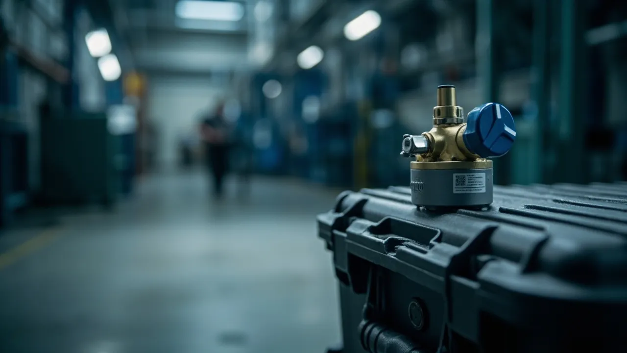
Short answer: a pressure equalization valve is not a breather hole — it is a differential-pressure balancing device that lets gas molecules through while blocking liquid water. Its core is an expanded polytetrafluoroethylene (ePTFE) breathable membrane, which achieves selective permeation because the pore diameter is far smaller than a water droplet yet far larger than a gas molecule. So the real question when specifying is not whether a valve exists, but how it performs across five parameter groups: air flow (permeability), water protection and water entry pressure, dust and particle blocking, temperature and chemical compatibility, and mounting structure and seal interface. These five groups trade off against each other — a more breathable membrane usually has a lower water entry pressure, and a denser membrane equalises pressure more slowly. Specification is therefore an exercise in trade-offs, not in maximising every number. This article provides a quantitative estimate of the pressure sources, the working mechanism of the ePTFE membrane, definitions and test conditions for the five key parameter groups, a comparison of four common membrane materials, a joint verification method for valve and IP rating, a troubleshooting path for six typical failure modes, and a parameter checklist you can paste straight into an enquiry.
One widespread misconception needs correcting first: many people assume a sealed case needs no openings at all, and in real use that causes worse problems. A fully sealed case develops an internal-to-external pressure difference under temperature change, altitude change or air freight. That differential presses the lid tighter or pushes it open, causing difficult opening, seal deformation and even permanent failure. A pressure equalization valve is therefore not a compromise on sealing but a necessary part of the sealing system. Together with the seal and the latches, it determines how the case behaves in the real environment. For the sealing principle, see outdoor protective case waterproof design.
Table of Contents
- Short Answer: A Valve Balances Pressure, It Is Not a Vent
- Why a Sealed Case Needs a Valve: Three Pressure Sources Quantified
- How the Valve Works: Selective Permeation Through an ePTFE Membrane
- Key Parameter One: Air Flow and Its Test Conditions
- Key Parameter Two: Ingress Protection and Water Entry Pressure
- Key Parameter Three: Dust and Particle Blocking
- Key Parameter Four: Temperature Range and Chemical Compatibility
- Key Parameter Five: Mounting, Structural Strength and Seal Interface
- Membrane Comparison: ePTFE, PP, PE and PU
- Joint Verification of Valve and IP Rating
- Six Typical Failure Modes and Troubleshooting Paths
- Selection Workflow and Parameter Checklist
- Valve Provisioning in OEM/ODM Projects
- Frequently Asked Questions
- Conclusion and Further Reading
Short Answer: A Valve Balances Pressure, It Is Not a Vent
Define the object precisely and every later parameter gains a reference frame.
A pressure equalization valve is a controlled, uni- or bi-directional micro-channel whose only permeating phase is gas.
It must satisfy two apparently contradictory requirements at once:
- High gas throughput. The internal-to-external pressure difference must be equalised within an acceptable time, typically seconds to minutes for the main equalisation.
- Complete liquid water blocking. Under rain, spray and short-term immersion, no liquid water may pass, while some water vapour (gaseous) permeability is retained to avoid moisture build-up inside.
The physical basis of both requirements is a difference in scale. The smallest liquid droplets are on the order of tens of micrometres, while the kinetic diameters of water vapour and the main air components (nitrogen, oxygen) are on the order of 0.3 nm — about five orders of magnitude apart. A breathable membrane exploits this gulf by setting the pore diameter at 0.1-1 micrometre: far smaller than a droplet, far larger than a gas molecule — hence "gas through, water not."
One point must be made clear: a breathable membrane blocks liquid water, not water vapour. Water vapour permeates slowly in and out of the case. Where internal humidity must be tightly controlled, a valve cannot replace a desiccant; the two are complementary, not substitutes. For the definition of ingress protection levels, see understanding the IP67 rating.
Why a Sealed Case Needs a Valve: Three Pressure Sources Quantified
Pressure difference is the only reason the valve exists. In engineering terms there are three main sources.
Source one: temperature change (the most frequent). In a closed vessel, gas pressure is approximately proportional to absolute temperature (ideal gas law). If the internal temperature rises from 20 C to 50 C, absolute temperature goes from 293 K to 323 K, and at constant volume the differential is roughly
dp is approximately p0 times (T2 - T1) / T1, that is 101.3 kPa times (323 - 293) / 293, which is about 10.4 kPa
In other words, a 30 C temperature rise produces about 10 kPa of differential pressure. That is equivalent to roughly a 1 m water column and is enough to visibly deform a large lid or to displace the seal. A real case has some elasticity that partially relieves the differential, but the residual is still significant. Conversely, cooling from 50 C to 20 C creates an opposite negative pressure that pulls the lid tighter, making it hard to open.
Source two: altitude and air freight. Air cargo holds typically correspond to an equivalent altitude of 2,000-2,500 m or higher. At 2,400 m, atmospheric pressure is about 75 kPa, roughly 26 kPa below sea level. If the case is sealed on the ground and then flown, the interior remains at 101 kPa, so internal pressure exceeds external by about 26 kPa — enough to push the seal open at a gap and bulge the lid, which is then sucked into deformation after landing.
Source three: rapid temperature change (thermal shock). Moving a case from an air-conditioned vehicle into a sun-exposed truck body, or from a cold store into ambient air, creates a steeper pressure gradient, demanding higher instantaneous permeability.
All three sources point to the same design objective: "under worst-case differential pressure, equalise within an acceptable time without leaking." The key phrase is "acceptable time" — faster is not always better, because higher permeability usually means a thinner membrane or larger pores, eroding the water protection margin.
| Pressure source | Typical magnitude | Direction | Main impact | Mitigation |
|---|---|---|---|---|
| --- | --- | --- | --- | --- |
| Temperature change (30 C rise) | About 10 kPa | Positive (negative on cooling) | Lid deformation, hard opening | Valve plus elastic seal design |
| Air freight / altitude (2,400 m) | About 26 kPa | Positive (negative after landing) | Seal pushed open, lid bulge | Valve, bi-directional preferred |
| Rapid temperature change | Peaks above steady state | Bi-directional | Instantaneous shock to membrane | Higher instantaneous flow design |
| Deep immersion | About 100 kPa per 10 m | External positive | Reverse differential, tests water resistance | Water entry pressure margin plus seal structure |
How the Valve Works: Selective Permeation Through an ePTFE Membrane
With pressure understood, turn to the membrane. ePTFE (expanded polytetrafluoroethylene) is the most common membrane material in protective case valves, characterised by a microporous fibril-node network formed by biaxial stretching.
Three key structural features:
- Pore size distribution. Typical pores are on the order of 0.1-1 micrometre, far below the smallest droplet diameter, so liquid water cannot penetrate under normal surface tension.
- Porosity. Typical porosity reaches 70-85%, and high porosity delivers high flux so gas can equalise pressure quickly.
- Chemical inertness. PTFE is chemically highly stable, resisting acids, alkalis and most solvents, with a wide temperature range.
The mechanism of selective permeation. Gas molecules (kinetic diameter about 0.3-0.4 nm) are far smaller than the pores and pass through by viscous flow and Knudsen diffusion. Liquid water must first overcome surface tension to enter a pore, and its intrusion pressure can be estimated from the Laplace relation:
p_intrusion is approximately 4 gamma cos(theta) / d
where gamma is the surface tension of water (about 72 mN/m), theta is the contact angle, and d is the pore diameter. With d = 0.5 micrometre and complete wetting (cos theta = 1), the intrusion pressure works out to about 5.8 x 10^5 Pa, or 580 kPa, equivalent to roughly a 58 m water column. This shows that, in theory, an ePTFE membrane has a high water resistance margin. Actual products, however, have far lower water resistance, because the mounting seal, the membrane support structure and surface contamination sharply reduce the real margin — a point covered under failure modes below.
Note carefully: the hydrophobicity of ePTFE depends on surface tension. Once the membrane surface is wetted by a surfactant (such as detergent), oil or certain solvents, the contact angle falls, the intrusion pressure drops sharply, and the membrane becomes water-permeable. This is one of the most common causes of real-world valve failure. For membrane and case material matching, see protective case plastic materials compared.
Key Parameter One: Air Flow and Its Test Conditions
Air flow determines how fast pressure equalises and is the valve's primary functional parameter, but it means nothing without its test conditions.
Four factors govern air flow: effective permeable area, membrane thickness, pore size and porosity, and test pressure differential. Double the effective area and flux roughly doubles; change the test differential and flux can vary several-fold.
Common ways of expressing it:
- Air flow. Gas volume passing per unit time at a specified differential, commonly in L/min or mL/min, and the test differential (for example 1 kPa, 5 kPa, 10 kPa) must be stated.
- Air permeability. Gas transmission per unit area, used to compare the membrane itself.
- Pressure equalisation time. The time for a given differential to decay to a target value, the metric closest to real use and best specified directly.
A practical estimation method. Given the valve's air flow Q (L/min) at a differential, the time to roughly equalise a free air volume V (L) is
t is approximately V / Q
For example, with a 20 L free air volume and 2 L/min flow, main equalisation takes about 10 minutes. This ignores the flux decay as the differential falls, so real time is longer, but it is adequate for initial selection. In engineering practice it is safer to ask the supplier for a pressure-equalisation time curve, or to measure on the target case.
| Parameter | Unit | Test condition to state | Selection significance |
|---|---|---|---|
| --- | --- | --- | --- |
| Air flow | L/min or mL/min | Test differential (kPa) | Determines equalisation speed |
| Air permeability | L/(min per cm2) or equivalent | Differential, area | For membrane comparison |
| Pressure equalisation time | s or min | Initial differential, case volume | Closest to real use |
| Breathing cycle endurance | Cycles | Cycle differential range | Membrane fatigue life |
| Initial differential retention | kPa | Time and volume | Combined sealing and flow indicator |
An easily overlooked point: higher air flow is not better. Excessively high flow is usually achieved by thinner membranes or larger pores, sacrificing water resistance and dust blocking. For alpine, air freight and cold-water washing scenarios, it is better to give up some equalisation speed than to lose the water protection margin.
Key Parameter Two: Ingress Protection and Water Entry Pressure
Water protection is the valve's second core parameter, and three distinct concepts must be separated.
Concept one: IP rating. As part of the case, the valve's water protection appears in the whole-enclosure ingress protection test. Under IEC 60529 / GB/T 4208-2017, relevant levels are commonly IPX7 (short-term immersion, typically 1 m for 30 min) and IPX8 (continuous immersion, conditions agreed between manufacturer and user). The key point: the rating is a whole-enclosure metric, not a membrane metric. A poorly mounted membrane can perform far worse in the assembly than the membrane alone would suggest.
Concept two: water entry pressure (WEP). The pressure at which leakage begins on a test rig, usually in kPa or mH2O. It is a membrane-level metric used to compare membranes and cannot be equated directly with the whole-enclosure rating. As a rule, the whole-enclosure requirement should be one-third to one-fifth of the membrane WEP, preserving margin for mounting and contamination.
Concept three: water vapour transmission rate (WVTR). The rate at which water vapour passes through the membrane, reflecting moisture discharge capability, which can be referenced to water vapour transmission test methods such as ASTM E96. This does not contradict "waterproof": the membrane blocks liquid water while allowing water vapour to pass slowly. For long-term storage cases, some WVTR helps prevent internal moisture build-up.
| Protection objective | Corresponding definition | Typical whole-enclosure requirement | Suggested membrane WEP | Notes |
|---|---|---|---|---|
| --- | --- | --- | --- | --- |
| Rain protection | IPX4 and above | No harmful ingress | Above 50 kPa | Most common scenario |
| Spray protection | IPX5 / IPX6 | No harmful ingress under strong spray | Above 100 kPa | Washdown, ship decks |
| Short-term immersion | IPX7 | 1 m for 30 min | Above 200 kPa | Common industrial requirement |
| Continuous immersion | IPX8 | Agreed conditions | Above 400 kPa | Underwater equipment, fording transport |
The figures above are empirical design and verification targets; formal requirements should follow the agreed test conditions and acceptance criteria.
Key Parameter Three: Dust and Particle Blocking
When a valve equalises pressure, it also lets outside air into the case. If the contents are precision equipment, the particles in that air are contaminants. Dust blocking therefore matters as much.
IP6X (dust-tight) and the valve. IP6X requires that after testing in a dust chamber, no dust enters the enclosure. For a case with a valve, this means the valve must block particles. Because its pores are sub-micron, an ePTFE membrane has high blocking efficiency for most dust particles, so the membrane alone typically satisfies the requirement. In practice, failure tends to occur around the valve: the seat-to-wall assembly face and the membrane-to-gasket compression zone are the main ingress paths.
Selection advice. If the application involves dust (construction, mining, agriculture, desert transport), state in the parameter list that "the valve must block dust under working conditions" and verify it as part of the whole-enclosure IP6X test. Also confirm whether the membrane is treated for antistatic or oleophobic performance, because oily dust adheres to the surface, clogs the pores and reduces air flow.
On cleanability. Some valves are designed to be removable and cleanable, which suits dusty environments. Confirm the cleaning method (water rinse, air blow, ultrasonic) and how fully performance recovers, since cleaning itself can damage the membrane or disturb the seal interface.
Key Parameter Four: Temperature Range and Chemical Compatibility
Temperature range. The valve must meet temperature requirements at two levels: the structural parts (valve seat, gasket) and the membrane's dimensional stability and mechanical properties under thermal cycling. ePTFE has a very wide temperature range (on the order of -40 C to 200 C), but what usually limits the assembly is the gasket material and the bonding adhesive. Standard nitrile (NBR) hardens and loses elasticity at low temperature; silicone (VMQ) performs better when cold but has limited oil resistance; fluoroelastomer (FKM) offers the best temperature and chemical resistance at higher cost.
Effect of thermal cycling. Thermal cycling stretches and contracts the membrane repeatedly and can cause fatigue over time. Watch the breathing cycle endurance parameter and ask the supplier for air flow and WEP retention after thermal cycling.
Chemical compatibility. Assess three types of contact: the external environment (rain, salt spray, cleaning agents, oil); the internal atmosphere (solvent vapours, acid and alkali fumes); and the cleaning process (alcohol, isopropanol). A special warning: surfactants are the principal threat to ePTFE, because they lower surface tension and shift the membrane from hydrophobic to hydrophilic. Where detergents or surfactant-containing sprays are involved, choose a membrane with oleophobic and hydrophobic surface modification, and test WEP after immersion in the actual medium.
Weatherability. Long-term outdoor use also requires UV ageing assessment. Artificial weathering to the ISO 4892 series evaluates the property retention of membrane and structural parts.
Key Parameter Five: Mounting, Structural Strength and Seal Interface
The first four parameters describe membrane performance; the fifth determines whether that performance can actually be delivered.
Mounting method. Three common types: threaded screw-in, snap-in, and moulded-in. Each involves a trade-off:
| Mounting method | Seal reliability | Replaceability | Cost | Suitable scenario |
|---|---|---|---|---|
| --- | --- | --- | --- | --- |
| Threaded screw-in | High (with gasket) | Good (unscrew to replace) | Medium-high | Maintenance-prone, clogging-prone |
| Snap-in | Medium-high | Medium (clips may be damaged) | Medium | General volume production |
| Moulded-in | High (no interface when integrated) | Poor (not replaceable) | Low (at volume) | One-time seal, low cost |
Structural strength. A valve protrudes from the case surface and is vulnerable to impact. Confirm the body's impact and crush resistance, requesting material performance data to plastic mechanical test methods such as ASTM D638 / ASTM D790 where necessary, or simply run drop and step tests.
Seal interface essentials. Four interfaces must seal simultaneously: membrane to seat, seat to case wall, gasket to mating face, and the fastener penetration. The practical approach is to mount the valve on a locally thickened platform at least 1.5 times the main wall thickness with ribs at its edge, so that tightening or loading does not deform the wall and break the seal. Position the valve away from low spots where water or dust collects, and out of the direct path of water jets. For structural design, see high-strength case structural design.
Membrane Comparison: ePTFE, PP, PE and PU
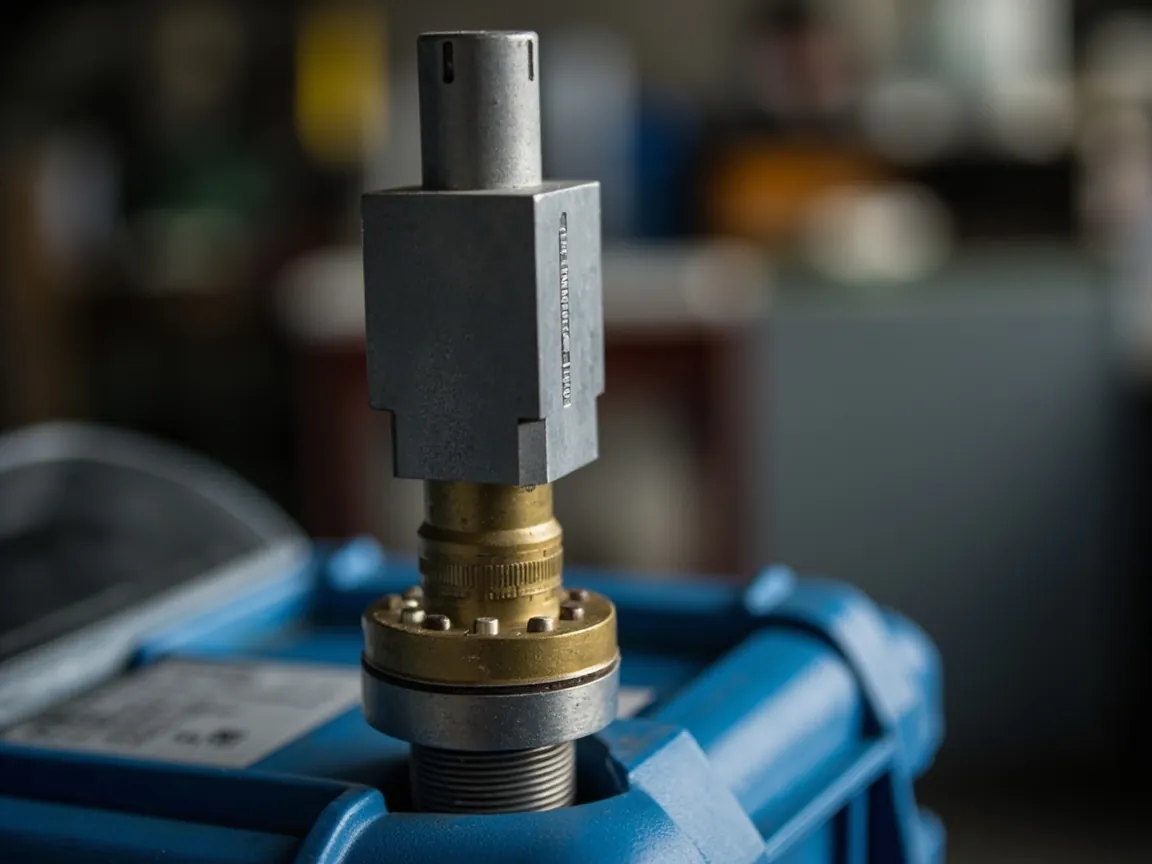
Not every valve uses ePTFE. The table below compares the performance orientation of common membrane materials (typical values; confirm with supplier data and test reports).
| Membrane | Water entry pressure | Air flow | Temperature | Chemical stability | Relative cost | Typical use |
|---|---|---|---|---|---|---|
| --- | --- | --- | --- | --- | --- | --- |
| ePTFE (expanded PTFE) | High | Medium-high | Very wide | Excellent | High | Protective cases, outdoor equipment, industrial enclosures |
| PP (microporous polypropylene) | Medium | High | Medium | Good | Low | General venting, cost-sensitive |
| PE (microporous polyethylene) | Medium | Medium-high | Medium | Good | Low | Consumer, light enclosures |
| PU (polyurethane) | Low | Low | Medium | Medium | Medium | Moisture-permeable textile, non-high-pressure |
| Oleophobic ePTFE | High | Medium | Very wide | Very good (oil resistant) | Very high | Oil mist, dust, detergent environments |
Three selection judgements:
- For high differential and high water protection, choose ePTFE. In air freight, high altitude and deep immersion, ePTFE has the best overall margin.
- For cost-sensitive, dry environments, PP/PE may suffice, but re-assess dust blocking and temperature margin.
- Where oil exposure is possible, use an oleophobic membrane. Standard ePTFE loses much of its water protection once wetted by oil.
Joint Verification of Valve and IP Rating
A valve must be verified as part of the whole enclosure; testing the membrane in isolation is meaningless. Run verification at three levels.
Level one: pressure equalisation verification (mandatory at first article). Two methods. First, the thermal cycling method: place the sealed case in a chamber from -20 C to 60 C and back to -20 C for several cycles, recording internal pressure (a miniature data-logging pressure sensor works well) and appearance each cycle. Second, the vacuum or pressurisation method: evacuate or pressurise the case to establish an initial differential and record the decay time to the target value. The second is more direct and repeatable, suiting production sampling.
Level two: whole-enclosure ingress protection verification. Run dust (IP6X) and water (IPX7/IPX8) tests to IEC 60529 / GB/T 4208-2017 with the valve fitted. Critical point: measure air flow before and after the test, because water ingress or dust clogging usually shows up simultaneously as reduced air flow. For the immersion method, see IP67 submersion testing.
Level three: environmental and endurance verification. Add as required:
- Thermal cycling plus damp heat, in the spirit of MIL-STD-810H Method 507 (humidity).
- Rain, per MIL-STD-810H Method 506 or IPX4/IPX5.
- Salt spray, per ISO 9227, assessing corrosion of metal parts and the valve body.
- UV ageing, per the ISO 4892 series, for long-term outdoor service.
- Breathing cycle endurance, applying repeated differential cycles to the membrane and recording the degradation curve.
A frequently overlooked verification detail: verify the valve in its actual working state. Some proposals plug the valve during testing "to ensure the IP test passes," but such results do not represent real use. The valve must take part in the test while open to atmosphere. For consistency between whole-enclosure verification and drawing parameters, see case drawings and technical parameters.
Six Typical Failure Modes and Troubleshooting Paths
Valve failure is usually not "the membrane broke" but a system problem. Six of the most common modes follow.
Mode one: membrane wetted by surfactant, causing water permeation. Water enters after rain or immersion while the membrane looks intact. Check whether the environment involves detergent, cleaning agent or surfactant-containing spray; switch to an oleophobic membrane and shorten the cleaning interval.
Mode two: oil or dust clogging the pores. Air flow falls, equalisation slows, the case is hard to open. Measure air flow and compare with the initial value; add a protective cover, switch to a cleanable design or an oleophobic membrane.
Mode three: mounting-face seal failure. Water seeps from the edge of the seat rather than the centre of the membrane. Run a localised spray test and observe the ingress path; thicken the mounting platform, replace the gasket, control tightening torque.
Mode four: case wall deformation around the seat. The wall deflects inward after tightening and the gasket compresses unevenly. Remove the valve and check for residual deformation; thicken the mounting platform and add ribs.
Mode five: gasket hardening at low temperature. Water ingress or abnormal equalisation in cold conditions. Run low-temperature cycling; change to a gasket material with better cold performance such as silicone or low-temperature FKM.
Mode six: mechanical membrane damage from excessive differential. Cracks or perforations, mostly after rapid temperature change or high differential shock. Calculate the worst-case differential against membrane rating; select a higher-rated membrane or add structural buffering.
General troubleshooting principle: first decide whether this is a membrane problem or an interface problem, then whether it is a contamination problem or a structural problem. In practice, interface and contamination failures are far more common than membrane rupture.
Selection Workflow and Parameter Checklist
Condense the analysis into an executable workflow.
Step 1: define the scenario. Air freight? High altitude? Deep immersion? Dust and oil? Detergent contact? Long-term outdoor exposure? What temperature range?
Step 2: calculate the worst-case differential. Estimate by the temperature method and the altitude method above, take the maximum, and apply an empirical safety factor (2-3 times is suggested).
Step 3: set the whole-enclosure protection target. Decide IPX4, IPX5, IPX6, IPX7 or IPX8, and state the test conditions (depth, duration).
Step 4: choose the membrane and mounting method. High differential and high water protection: ePTFE with threaded mounting. Cost-sensitive dry environment: PP/PE with snap-in or moulded-in. Oil exposure: oleophobic membrane.
Step 5: request parameters and verification documents using the checklist below, confirming that test conditions are complete.
Step 6: measure pressure equalisation at first article and verify whole-enclosure IP.
Step 7: write into the agreement and define acceptance criteria.
| Information to request in an enquiry | Explanation | Consequence if missing |
|---|---|---|
| --- | --- | --- |
| Air flow and test differential | Differential must be stated | Cannot compare options |
| Pressure equalisation time | Against target case volume | Cannot judge adequacy |
| Membrane water entry pressure | Membrane-level metric | Cannot set mounting margin |
| Whole-enclosure IP verification method | Level and test conditions | No shared basis for acceptance |
| Membrane type and oleophobicity | Whether surface-modified | Wrong membrane for oily scenarios |
| Temperature range and cycle endurance | State structural parts and membrane separately | Low-temperature failure risk |
| Mounting method and torque | Threaded / snap / moulded | Leaks from poor assembly |
| Cleanability and life | Cleaning method and recovery | Maintenance cost out of control |
Valve Provisioning in OEM/ODM Projects
In OEM/ODM projects, valve provisioning involves three additional considerations.
First, synchronise with case design. The valve mounting platform, ribs and opening should be considered at the tool design stage, not added after the tool is complete. Drilling later costs more and may damage the existing seal structure. The valve should therefore be an input to case design, confirmed at drawing review.
Second, match the customer's duty. Customer duties vary widely: a logistics packaging case may need only rain protection, while a marine equipment case must withstand continuous immersion and salt spray. The same case body should be fitted with different valve grades for different duties, rather than a single lowest-cost configuration. Write the duty into the technical agreement to avoid fitting the cheapest option to the harshest duty.
Third, integrate with the after-sales system. The valve is a serviceable part. Agree the spare supply route and replacement interval in the agreement, and for threaded valves supply a replacement tool and torque instruction to avoid field assembly errors.
JUNZHJIA, manufactured by KeXin New Materials (Guangdong) Co., Ltd., configures valve membrane, mounting method and protection level to the customer's duty, providing measured pressure equalisation data, whole-enclosure IP verification and spare parts, and in wholesale, distribution and OEM/ODM projects supplies drawing review and test documentation.
Frequently Asked Questions
Q: What exactly is the pressure equalization valve for, and what happens without it? A: Its core function is to balance the pressure difference between inside and outside, so a sealed case does not deform or fail under temperature change, altitude change or air freight. Without a valve, a fully sealed case shows four practical problems. First, after cooling, internal negative pressure pulls the lid tight and makes it very hard to open, sometimes needing two people or a tool. Second, after warming, internal positive pressure bulges the lid and pushes the seal open at a gap, breaking the seal. Third, in air freight the differential can exceed 20 kPa and may permanently deform the seal. Fourth, repeated pressure cycles accelerate seal fatigue. Note that a valve is not a compromise of "drilling a hole in the seal" but a component of the sealing system: it passes gas molecules but not liquid water, so it does not contradict waterproofing. The one clarification is that a breathable membrane cannot block water vapour, so scenarios needing tight internal humidity control still require a desiccant.
Q: Is higher air flow always better, and how do I know it is enough? A: No — the target is "sufficient with a water protection margin." A membrane with excessively high flow is usually thinner or has larger pores, sacrificing water resistance and dust blocking. To judge adequacy, use a simplified equalisation time estimate: time is roughly the free air volume divided by the air flow at that differential. For example, with a 20 L free air volume and 2 L/min, the main equalisation takes about 10 minutes, and real time is longer once flux decay is allowed for. It is safer to request a pressure-equalisation time curve from the supplier or to measure on the target case. Two traps to avoid: air flow must state the test differential, otherwise numbers cannot be compared; and the free air volume is not the nominal case volume but the internal volume less the volume occupied by contents and inserts. For alpine, air freight and cold-water washing, give up some equalisation speed rather than the water protection margin.
Q: With a valve fitted, can the case still reach IP67? A: Yes — that is precisely why the valve is designed. IPX7 within IP67 requires no ingress during short-term immersion, and the valve blocks liquid water through the membrane while allowing gas through to equalise pressure, so the two do not conflict. But note three things. First, the rating is a whole-enclosure metric, not a membrane metric: a poorly mounted membrane can perform far worse in the assembly, so verification must be done with the valve fitted, never with it plugged. Second, the mounting interface is the key risk point — seat to wall, gasket to mating face, and fastener penetration must all seal simultaneously, so mount the valve on a locally thickened platform with ribs at the edge. Third, keep a margin on membrane WEP: as a rule the whole-enclosure requirement should be one-third to one-fifth of the membrane WEP to absorb mounting and contamination losses. For test methods, refer to IEC 60529 and GB/T 4208-2017.
Q: Why do some valves become water-permeable after a period of use? A: The most common cause is not membrane rupture but membrane wetting. The water resistance of ePTFE depends on surface tension: water must overcome surface tension to advance into a pore, so intrusion pressure is high. But once the surface contacts a surfactant (detergent, cleaning agent, surfactant-containing spray), oil or certain solvents, the contact angle falls sharply, intrusion pressure collapses, and the membrane becomes hydrophilic and water-permeable. Other causes include mounting-face seal failure letting water in from the seat edge; oil or dust clogging the pores followed by high-pressure washing that drives water through the membrane; and gasket hardening at low temperature. Troubleshoot by identifying the ingress path: water from the membrane centre usually means wetting or clogging, water from the seat edge usually means mounting seal failure. Use an oleophobic membrane in oily environments, with a protective cover or a cleanable design.
Q: How should I choose the membrane material? Is ePTFE always necessary? A: Not necessarily; it depends on the duty. ePTFE offers the best overall margin: high water entry pressure, medium-high air flow, a very wide temperature range and excellent chemical stability, suited to air freight, high altitude, deep immersion and long-term outdoor use, but it costs the most. Microporous PP and PE are low cost with high air flow, suited to dry, oil-free, cost-sensitive general use, but with lower water resistance and temperature margin, requiring reassessment of dust blocking and endurance. PU has good moisture permeability but low water entry pressure and is generally used in textiles and non-high-pressure applications, not for immersion-rated cases. A further class is oleophobic-modified ePTFE, retaining high water resistance while improving oil resistance, suited to oil mist, dust and detergent environments, at higher cost. Selection can be summed up in three lines: for high differential and high water protection, prefer ePTFE; for cost-sensitive dry environments, PP/PE may serve; where oil exposure is possible, use an oleophobic membrane.
Q: What matters about valve mounting position and method? A: Three mounting methods exist: threaded screw-in, snap-in and moulded-in. Threaded with a gasket gives reliable sealing and replaceability, suiting maintenance-prone or clogging-prone scenarios; snap-in sits in the middle on cost and reliability, suiting general volume production; moulded-in has no interface, seals best and costs least at volume, but is not replaceable, suiting one-time-seal low-cost solutions. On position, four points: avoid low spots where water collects, or standing water will test the seal and membrane; do not face the direct path of water jets, especially under high-pressure washdown; mount on a locally thickened platform, at least 1.5 times the main wall thickness with ribs at the edge, to prevent wall deformation when tightening or loading; and avoid load-concentrated zones, to reduce shock transmission in a drop. For assembly, state the tightening torque: too much can crush the gasket or deform the wall, too little gives insufficient sealing.
Q: How do I verify the pressure equalisation performance of a valve? A: Two methods are recommended, chosen by accuracy and scenario. The first is the vacuum or pressurisation method: establish an initial differential by evacuating or pressurising the case and record with a pressure sensor the time for the differential to decay to the target. This is direct and repeatable, suited to production and incoming sampling, and makes it easy to set a differential-time acceptance standard. The second is the thermal cycling method: place the sealed case in a chamber from -20 C to 60 C and back to -20 C for several cycles, recording internal pressure and appearance each cycle. This is closer to real use and exposes gasket hardening at low temperature and wall deformation, suiting first-article verification. Both should be paired with whole-enclosure ingress protection testing to IEC 60529 / GB/T 4208-2017, measuring air flow before and after, because water ingress or dust clogging usually shows up as reduced air flow. To assess long-term tolerance, add MIL-STD-810H humidity and rain methods, ISO 9227 salt spray and ISO 4892 UV ageing.
Q: What special considerations apply to air freight or high-altitude transport? A: Air freight and high altitude are among the harshest duties for a valve, and three points apply. First, prefer a bi-directional breathing structure: during ascent, internal positive pressure must vent outward, and after landing the relative negative pressure must draw air inward; if the valve only works one way, the case stays under negative pressure after landing, making the lid hard to open or even inverting the seal. Second, check against the worst-case differential: at an equivalent 2,400 m, external pressure is about 75 kPa, roughly 26 kPa below sea level, and this internal differential is enough to push the seal open, so check membrane rating and mounting structure against it with an empirical safety factor of 2-3. Third, verify the full cycle: do not test only the ascent direction, but run a complete pressurise-then-depressurise cycle and look for residual deformation. If the case carries air-transport-restricted items such as lithium batteries, also confirm the packaging meets dangerous goods requirements; the valve itself only needs to provide anti-opening and basic protection.
Q: Does a valve need maintenance, and how long does it last? A: Yes, the valve is a serviceable part and its life is usually set by the membrane and the gasket together, not by a single component. Three maintenance recommendations. First, check air flow periodically: use a simple method such as applying a fixed differential with a syringe and observing the decay time against the initial value; a marked slowdown suggests clogging. Second, clean according to the duty: in dusty conditions use low-pressure air or a water rinse, but avoid directing a high-pressure jet at the membrane, since it can drive water through or damage the membrane; in oily conditions use a cleanable design and confirm performance recovery after cleaning. Third, replace the gasket periodically: rubber gaskets age and harden, especially after repeated low-temperature cycling, so replace by service age. On life: in mild conditions (indoor, dust-free, oil-free) a valve can serve for years; in harsh conditions (dust, oil, frequent thermal cycling, long-term outdoor) inspect annually and replace when performance falls. Agree the spare supply route, replacement interval and torque requirement in the agreement.
Conclusion and Further Reading
Back to the title question: specifying a valve is essentially a trade-off between pressure equalisation speed and water and dust protection margin, not the pursuit of a single maximum parameter. The five parameter groups — air flow and its test conditions, ingress protection and water entry pressure, dust and particle blocking, temperature and chemical compatibility, and mounting structure and seal interface — must be assessed together, because any one viewed in isolation can mislead. The core mechanism is that ePTFE pore size sits between a gas molecule and a water droplet, delivering "gas through, water not," but water resistance depends on surface tension, so oil and surfactants are the greatest practical threat.
Three actionable recommendations: first, calculate the worst-case differential using the temperature method (about 10 kPa for a 30 C rise) and the altitude method (about 26 kPa at 2,400 m), and keep a 2-3 times margin. Second, treat the rating as a whole-enclosure metric — test to IEC 60529 / GB/T 4208-2017 with the valve fitted, and measure air flow before and after. Third, treat the mounting interface as the primary risk point — thicken the platform, add ribs and control tightening torque, because interface and contamination failures are far more common than membrane rupture.
JUNZHJIA, manufactured by KeXin New Materials (Guangdong) Co., Ltd., supplies protective cases, tool boxes, military-specification storage cases and waterproof junction boxes for wholesale, distribution, OEM/ODM and global supply, configuring valve membrane and protection level to the duty and providing measured pressure equalisation data and whole-enclosure verification documentation.
Further Reading