


The short answer: yes, and a divider system is the single most cost-effective upgrade for getting a protective case to serve more than one product. But it has to respect three hard limits — it must not disturb the lid seal, it must not weaken stacking strength, and it must not make internal dimensions indeterminate after repeated assembly. Dividers and foam inserts are two different engineering routes. Foam buys protection through conformity and suits items with a fixed shape. Dividers buy reusability through adjustability and suit mixed contents, multiple variants and variable batch sizes. Confusing the two is the most common specification error in custom programs: using foam for mixed contents means a new insert every time the product changes, while using dividers for fragile precision parts means the parts collide inside their compartments in transit.
This article breaks "can you add dividers" into executable design questions: which routes exist and what each suits; whether a divider acts as a partition or as a structural column, and what that means for ribbing; how slot pitch, slot width and panel thickness form a tolerance chain; how to choose between friction, snap, magnetic and clamp retention; why the sealing zone is strictly off limits; the three ways to add a divider system and what each costs; and a set of hygiene requirements for medical and laboratory use. Figures are typical or empirical, and any real project should be confirmed against the case drawing, measured internal dimensions and physical validation.
Contents
- The short answer: yes, within three hard limits
- Four engineering routes to a divider system
- A divider is not only a partition, it may be a column
- Slot design: matching pitch, width and panel thickness
- Retention: friction, snap, magnetic and clamp
- Protecting the sealing zone: the one absolute rule
- Material choices from PP and ABS to EVA and composites
- Load path and anti-shift design
- Levels of removability and assembly-cycle life
- Three ways to add a divider system
- Cleaning, disinfection and hygiene design
- Dividers versus foam inserts, and combining them
- Application configurations and a selection table
- Frequently Asked Questions
- Conclusion and Related Reading
The short answer: yes, within three hard limits
Three limits define the boundary of every design decision that follows.
Limit one: the divider system must not change the geometry of the lid sealing surface. Sealing depends on two things — the flatness of the mating surface between case and lid, and the compression of the gasket in its groove. Any slot, hole or sustained lateral force applied to the sidewall near the case mouth can distort that surface and destroy the ingress protection rating. All retention features must sit below the gasket groove, with a defined safety margin.
Limit two: the divider system must not reduce stacking strength. Vertical load in a stacked case is carried mainly by the sidewalls and their ribs. Cutting long horizontal slots into a sidewall creates stress raisers in the loaded section. An empirical rule: slot depth no more than twenty-five percent of wall thickness, and cumulative slot length no more than sixty percent of that sidewall's length, with slot positions kept clear of the main vertical ribs.
Limit three: internal dimensions must stay determinate after assembly cycles. The classic failure of removable systems is loosening with every cycle. If retention relies on interference friction, the mating surfaces wear, the divider starts to move, and contents shift in transit. Decide up front whether location comes from friction, from a mechanical snap, or from a top plate clamping the assembly. Only the latter two hold position reliably over a long service life.
| Limit | Specific restriction | Consequence of failure | Design response |
|---|---|---|---|
| --- | --- | --- | --- |
| Preserve the seal | Retention features must stay below the sealing-zone safety margin | Loss of IP rating, leakage | Move fixing points lower; zero machining in the seal zone |
| Preserve strength | Slot depth at or below twenty-five percent of wall; cumulative length at or below sixty percent | Stacking deformation, sidewall bulge | Avoid main ribs; add local reinforcement |
| Repeatable location | Retention must not rely on interference alone | Loosening and shifting after cycles | Use snaps, top plates or lid clamping |
Four engineering routes to a divider system
"Add dividers" maps to four quite different constructions, and choosing the wrong route costs far more than the panels themselves.
Route one: slot-in rigid panels. Equally spaced slots are moulded into the sidewalls or base, and rigid panels slide in to form compartments. Adjustability is good, panels can be removed for cleaning, and load capacity is high. The cost is that slots must be built into the tool or machined afterwards. This route suits mixed tools, equipment and spare parts.
Route two: foam slot systems. Layers of EVA or PE foam are stacked and cut so panels can be inserted between them. Nothing about the case is modified, so the system can be added at any time. The drawbacks are that foam compresses, so slots loosen over time, and foam consumes significant volume. This route suits small custom runs and prototype stages.
Route three: modular grid frames. A set of standardised beams and posts forms a reconfigurable grid skeleton. Flexibility is the highest of the four, and the whole assembly can be lifted out. The drawbacks are part count, self-weight and the learning curve for assembly. This route suits users who change their compartment layout often, such as field service and inspection teams.
Route four: removable tray boxes. Instead of dividers, several shallow trays or small boxes sit inside the case. Each can be carried out on its own. The disadvantage is usually lower volumetric efficiency, because walls and gaps between boxes waste space.
| Route | Up-front cost | Flexibility | Volume efficiency | Self-weight | Best fit |
|---|---|---|---|---|---|
| --- | --- | --- | --- | --- | --- |
| Slot-in rigid panels | Medium to high (tool or machining) | High (equal pitch) | Medium to high (85–92 percent) | Medium | Tools, equipment, spares |
| Foam slot system | Low (retrofittable) | Medium | Medium to low (70–82 percent) | Low | Small batches, prototypes |
| Modular grid frame | Medium | Very high | Medium (78–88 percent) | Higher | Frequently changing layouts |
| Removable tray boxes | Medium | Medium | Medium to low (72–85 percent) | Medium | Items carried separately |
Volume efficiency figures are empirical ranges and vary significantly with compartment count and content shape. Always confirm with a layout trial.
A divider is not only a partition, it may be a column
This is the most valuable and most frequently missed point in divider design: if a divider simultaneously touches the base and the lid or insert top surface, it stops being a partition and becomes a column, participating in vertical load carrying.
That explains two observations. First, a case filled with dividers often stacks better than an empty one, because vertical load transfers through the panels instead of being carried entirely by the sidewalls, which sharply reduces the bending moment on them. Second, a divider that hangs in mid-air without touching the top contributes almost nothing to stacking, because it only prevents mixing and does nothing for how high the case can be stacked.
Three design rules follow.
- If the goal is stacking capacity, set the divider height to contact both the case base and the lid inner surface or insert top, with a preload of 0.5 to 1.5 mm (empirical) so the load path is reliable.
- If the goal is compartmentalisation only, let the divider finish 2 to 5 mm below the case mouth, so lid closure does not impose continuous stress on the top edge.
- In neither case may the divider touch the lid sealing surface. The load path should land on the rigid non-sealing area of the lid, never on the sealing step.
The vertical load structure of a case is discussed in how high-strength case structures are built, where the ribbing principles follow exactly the same logic as using dividers as columns.
Slot design: matching pitch, width and panel thickness
Once slot-in panels are chosen, slot geometry decides success or failure. The difficulty is not cutting a slot; it is the tolerance chain linking slot width, panel thickness and pitch.
Slot width against panel thickness. The goal is a panel that slides in without rattling. Too tight makes insertion and removal difficult and wears or cracks the slot after repeated cycles. Too loose lets the panel move and contents shift. Empirical practice:
- For injection-moulded parts, set slot width W = panel thickness t + 0.3 to 0.6 mm to absorb shrinkage variation and assembly tolerance.
- If the panel carries a soft edge strip or foam tape, add that thickness into t.
- Insertion depth should be at least fifteen to twenty percent of panel height, and never less than 8 mm, or resistance to tipping is inadequate.
Choosing the pitch. Pitch sets the granularity of compartment sizes. Smaller pitch means finer adjustment but more slots, more weakening of the sidewall and higher tooling cost. Common pitch series are 10, 12.5, 15, 20 and 25 mm; round numbers let users find positions with a tape measure. The recommended approach is to make pitch a common divisor of the main item widths. If items run 60 to 120 mm wide, a 15 or 20 mm pitch covers the range well.
Allocating the tolerance chain. This step is most often skipped. The internal width carries a moulding tolerance, typically ±0.3 to ±0.5 percent depending on size, and the panel length carries its own tolerance. Stacked, the two can make a panel impossible to fit or obviously loose.
| Parameter | Suggested value (empirical) | Note |
|---|---|---|
| --- | --- | --- |
| Slot width W | Panel thickness t + 0.3 to 0.6 mm | Moulded part; covers shrinkage and assembly tolerance |
| Insertion depth | At least fifteen percent of panel height, and at least 8 mm | Minimum for tipping resistance |
| Panel length | Internal width minus 0.5 to 1.0 mm | Assembly clearance so it cannot jam the sidewall |
| Panel height | Internal height plus 0.5 to 1.5 mm preload when used as a column | Only for load-bearing dividers |
| Pitch | 10 / 12.5 / 15 / 20 / 25 mm | Common divisor of item widths |
| Slot depth | At or below twenty-five percent of wall thickness | Controls stress concentration and strength loss |
| Cumulative slot length | At or below sixty percent of that sidewall's length | Preserves sidewall bending capacity |
Chamfer or round every slot mouth. A sharp slot edge acts like a blade on the panel edge during repeated insertion, and the mouth itself is prone to cracking. An empirical 0.5 to 1.0 mm chamfer with a radius of at least R0.5 is the cheapest high-return detail in the whole design.
Retention: friction, snap, magnetic and clamp
How the panel holds position determines long-term reliability.
Friction through interference. Slot width is slightly smaller than panel thickness. Structurally the simplest option, with no extra parts, but retention decays with time and cycles and is sensitive to humidity and temperature. A common compromise is to fit a thin foam or soft rubber strip along the panel edge so an elastomer provides friction; interference can then be smaller and wear more even. Suits infrequent adjustment.
Mechanical snap. An elastic snap inside the slot or on the panel edge locks mechanically once inserted. Repeatable location and good vibration resistance. But the snap is a stress concentrator, so it needs a tough material such as modified PP or PA, and the release action must be designed properly. Suits frequent adjustment with vibration present.
Magnetic retention. Magnets embedded in the panel edge or a top strip hold position magnetically. It is extraordinarily convenient, tool-free and visually clean. The drawbacks are sensitivity to temperature, potential interference with magnetically sensitive contents, and possible displacement under strong vibration. Suits instrument cases, display cases and medical use, not ferrous powder or high-shock environments.
Clamping by a top plate. A rigid strip presses on the top edge of the panels, or the lid insert clamps the assembly. Location accuracy is the highest of the four, load distribution is even, and nothing depends on friction. The cost is that a single panel cannot be removed without opening the case. For column-type dividers this is in fact the natural retention method.
| Retention | Location repeatability | Vibration resistance | Ease of assembly | Extra parts | Best fit |
|---|---|---|---|---|---|
| --- | --- | --- | --- | --- | --- |
| Interference friction | Medium, decays | Medium | Medium | None | Infrequent adjustment |
| Friction with elastic strip | Medium to high | Medium to high | Medium | Foam or rubber strip | General purpose |
| Mechanical snap | High | High | Medium (needs release) | Snap feature | Frequent adjustment, vibration |
| Magnetic | Medium | Medium to low | Very high | Magnets, keeper strip | Instruments, display |
| Top-plate clamp | Very high | High | Low (lid must open) | Clamp strip | Column-type dividers |
Protecting the sealing zone: the one absolute rule

This deserves its own section, because it is where divider retrofits most often fail.
Separate three zones first. Looking up the inside of an open case, the sidewall divides into three bands: the sealing zone at the top where the gasket groove and sealing step sit; the main sidewall in the middle; and the base transition at the bottom. The sealing zone is strictly off limits: no slotting, no drilling, no sanding, no adhesive.
Why so strict? Sealing depends on the gasket being compressed evenly. Compression is extremely sensitive to gap: an increase of 0.2 mm at one location can cause a leak. If a slot is cut near the case mouth, local sidewall stiffness drops, and under sealing load the mating surface can deflect along that line, opening the gap. The failure mode is deceptive — the case looks perfect and leaks only at one specific spot.
Setting the safety margin. An empirical rule: the topmost edge of any retention feature should sit at least 1.5 to 2 times the wall thickness below the bottom of the gasket groove. For a 3 mm wall that means 5 to 6 mm of clear distance, which keeps the stress concentration from machining away from the distortion-sensitive area of the sealing surface.
A second hidden risk is lid preload. If a divider becomes a column with height interference, every closure pushes back against the lid. That reaction travels through the lid to the sealing surface, and sustained over time can permanently deform it. Two ways to avoid this: let the divider contact a rigid non-sealing area of the lid insert, and keep preload within a sensible 0.5 to 1.5 mm band rather than oversizing it in the name of firmness.
What if structure really is needed high on the sidewall? Two alternatives. Move the structure to the base, using base slots or base sockets so panels install from below, or move it into a separate removable insert that sits inside the case and has no machined relationship with the sidewall at all.
Material choices from PP and ABS to EVA and composites
Divider material balances stiffness, toughness, weight, cost and environmental resistance.
PP (polypropylene). The workhorse. Good chemical resistance, good low-temperature impact and low cost, available moulded or extruded. Its weakness is stiffness, so thin panels flex and need deep slots, top plates or ribs to compensate. Modified grades with glass fibre or impact modifiers improve stiffness and low-temperature toughness substantially.
ABS. Better stiffness and surface quality than PP, with good dimensional stability, which suits precisely fitting dividers and grids. Chemical resistance and outdoor weatherability are weaker than PP, and long UV exposure embrittles it.
PC (polycarbonate). High stiffness and transparency, suitable for viewing windows and thin high-stiffness panels. It costs more and has moderate resistance to stress cracking, so sharp corners and machining stress need attention.
EVA and PE foams. Used as the panels in foam slot systems, or as cushioning strips on the edges of rigid panels. EVA offers better elasticity and recovery for repeated insertion; PE foam is harder and cheaper, suited to single-use or low-frequency systems.
Composite and over-moulded panels. A rigid core for stiffness with a soft over-moulded skin for friction and protection, currently the best all-round solution. The cost is more parts and more process steps.
| Material | Stiffness | Low-temperature toughness | Chemical resistance | Weatherability | Typical use |
|---|---|---|---|---|---|
| --- | --- | --- | --- | --- | --- |
| PP | Medium to low | Good | Good | Good | General panels and grids |
| Modified PP (glass filled or toughened) | Medium to high | Good | Good | Good | Load-bearing and column panels |
| ABS | Medium to high | Medium | Medium | Medium to low | Precision-fit dividers |
| PC | High | Medium | Medium | Medium | Thin stiff panels, windows |
| EVA foam | Low | Good | Medium | Medium | Foam slots, edge strips |
| PE foam | Low | Medium | Good | Medium | Low-cost slots, spacers |
| Rigid core with soft skin | High | Good | Depends on core | Good | High-cycle, precision use |
Compatibility with the case body matters too: a panel material must not be chemically incompatible with the case material. Some plasticiser-bearing soft compounds, in prolonged contact with ABS, can cause crazing. Broader material selection is covered in choosing plastics for protective cases.
Load path and anti-shift design
A divider system sees forces in three directions and each needs checking.
Vertical. From stacking above, from the weight of contents, and from what a column carries. The check is that the panel must not buckle or sink into its slot. As an empirical guide, control the height-to-thickness ratio: for PP panels, buckling risk rises noticeably beyond about 25:1, and top plates or ribs push that limit higher.
Lateral. From transport acceleration and content shift. This is the most common failure — a panel pushed out of its slot by lateral load. Three countermeasures: deeper insertion, mechanical snaps, and interlocking panels arranged so longitudinal and transverse panels cross-lock into a rigid frame, whose stiffness far exceeds that of individual panels.
Longitudinal. From lifting the lid and from friction during loading and unloading. The usual result is a worn panel edge and a cut slot mouth. Chamfer the slot and round or cap the panel edge.
Three empirical anti-shift rules:
- Gap in each compartment should not exceed five to eight percent of the item dimension. Excess gap lets contents hammer the compartment walls, damaging both the contents and the dividers.
- Provide a top compression feature. If a compartment is not full, add a thin foam pad or elastic strip on top to remove vertical movement.
- Keep heavy items low and central. Placing heavy contents near the case's geometric centre and base lowers the centre of gravity and reduces lateral moment.
The trade-off between foam, which removes movement by filling, and dividers, which control it by compartmentalising, is set out in dividers versus foam for protective cases.
Levels of removability and assembly-cycle life
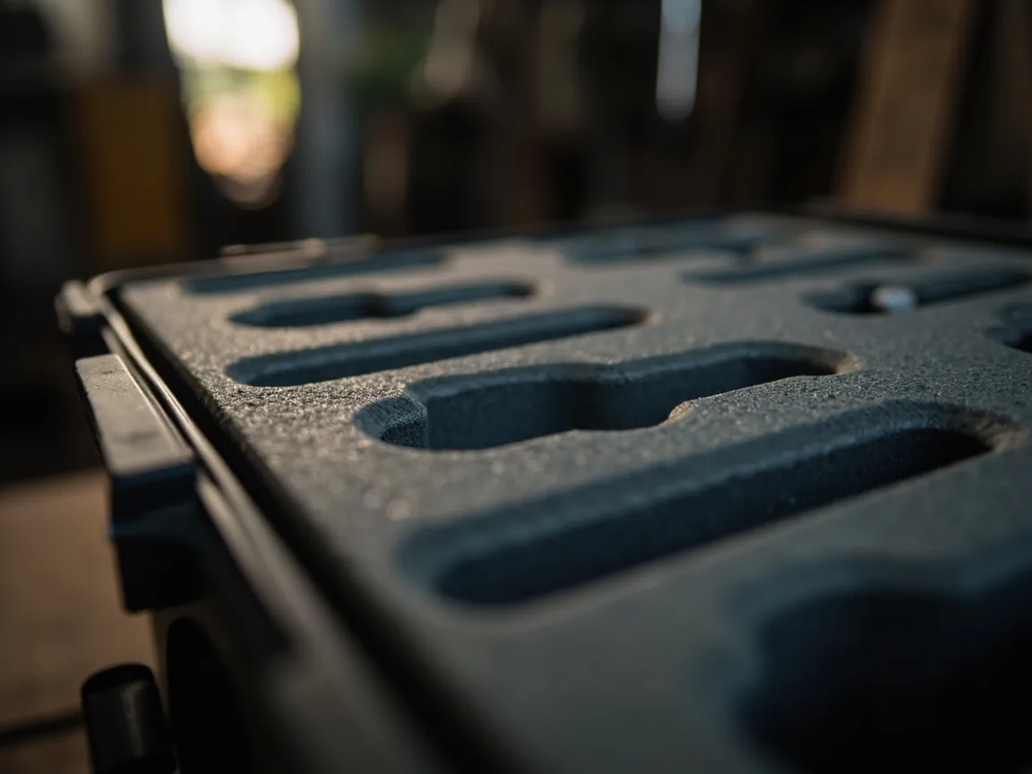
Removability is not binary. Define the level you need before defining the structure.
Level one: the whole assembly lifts out. The divider frame comes out as one piece, leaving an open cavity. Suits users who sometimes need compartments and sometimes need to carry one large item.
Level two: individual panels reposition. Each panel can be pulled and moved to a different slot. This is the most common level and the core value of a slot-in system. It requires equal pitch, consistent slot mouths and controllable panel tolerances.
Level three: tool-free adjustment. The user needs no tools. This is a strong requirement in field use and demands deliberate work on snap release, finger access and sliding resistance. A practical test: can someone wearing gloves reposition one compartment within thirty seconds?
Setting assembly-cycle life. It follows directly from frequency of use.
| Frequency | Typical scenario | Suggested cycle life | Structure |
|---|---|---|---|
| --- | --- | --- | --- |
| Low (a few times a year) | Long-term storage, quarterly stocktake | 50–200 cycles | Interference friction is adequate |
| Medium (several times a month) | Scheduled inspection, equipment maintenance | 500–2000 cycles | Elastic strip plus chamfered slots |
| High (several times a week) | Field repair, mobile service | 2000–10000 cycles | Snaps plus wear-resistant material |
| Very high (daily) | Production line kitting, daily dispatch | Above 10000 cycles | Metal or composite frame with replaceable wear parts |
Verification is straightforward. Run the specified number of insertion cycles on production parts, then re-measure three things: change in insertion force, which should not rise by more than fifty percent of the initial value; panel movement in the slot, which should stay within 1 mm; and any cracking at the slot mouth. Only when all three hold can the claimed cycle life be quoted.
Three ways to add a divider system
If a fleet of standard cases is already on the shelf, can dividers still be added? Three situations.
Option one: build the slots into the tool. This is the best route by a wide margin. It is the only way to get accurate slot positions, controllable tolerances and an unbroken appearance, and it is also the cheapest per unit, since only the tooling cost increases. Custom programs should take this route first. Slot dimensions and tolerances belong on the drawing, as described in case drawings and technical parameters.
Option two: machine the slots afterwards. Milling or sawing into a moulded case is feasible but costly. Consider the roughness and burrs on the cut surface, which must be deburred and chamfered; the release of internal stress, since interrupting the moulded skin-core structure can cause silver streaks at the slot mouth; the limits on depth and position, which must avoid the sealing zone and the main ribs; and the effect on any existing ingress protection certification, which normally requires re-verification of sealing, especially if the cut is anywhere near the case mouth.
Option three: use foam instead. Leave the case untouched and install a foam slot system or stacked cut foam. Nothing changes about the IP rating, it can be added at any time, and it can be redone. The cost is lower volume efficiency and slot loosening over time. It suits small batches and validation stages; the cutting and layering process is described in custom EVA foam insert processing.
Decision guide. If annual volume covers the incremental tooling cost, take option one. If cases are already in stock and the quantity is modest, take option three. Only consider option two when large numbers of finished cases already exist and rigid compartmentalisation is unavoidable, and always schedule a sealing re-verification.
Cleaning, disinfection and hygiene design
Medical, food and laboratory users add hygiene requirements, which concentrate in three places.
First, eliminate cleaning traps. Slot mouths, snap recesses and screw holes collect dust and liquid. Tool-free assembly is the preferred answer, replacing threaded fasteners with snaps or press fits, with slot bottoms either through-cut or generously radiused so no blind pockets form.
Second, choose materials that tolerate the cleaning agents in use. Common agents include isopropyl alcohol, sodium hypochlorite solution and quaternary ammonium compounds. PP and PE tolerate most of these well. ABS and PC are more sensitive to strong oxidising agents and can stress-crack. Write the specific agents into the technical agreement and have the supplier confirm compatibility.
Third, make the assembly lift out. If the whole divider frame comes out in one piece, it can be cleaned separately, even in a washing machine or washer-disinfector, rather than wiped in place. This matters a great deal in high-frequency medical and laboratory use.
One caution: frequent strong disinfection accelerates seal ageing. Even with a chemically resistant divider system, inspect the gasket for hardness change and compression set at intervals and replace as needed. Gasket compatibility is covered in choosing gasket and seal materials.
Dividers versus foam inserts, and combining them
Dividers and foam are not competitors. They are two protection layers that can be combined.
| Dimension | Rigid divider system | Foam insert | Combined approach |
|---|---|---|---|
| --- | --- | --- | --- |
| Mechanism | Compartmentalise to limit movement | Conform to absorb shock | Compartments plus wall cushioning |
| Reusability | High, change the layout | Low, new insert per product | Medium to high |
| Volume efficiency | 85–92 percent (empirical) | 45–80 percent | 78–88 percent |
| Per-item protection | Medium, mainly anti-shift | High, mainly anti-shock | High |
| Loading convenience | High | Low, requires alignment | Medium |
| Cleanability | Good | Medium, foam holds dust | Medium |
| Up-front cost | Medium to high | Low, retrofittable | Medium |
| Best fit | Mixed tools and equipment | Fragile items, fixed shapes | Fragile items with many variants |
A typical combined build: slot-in rigid panels form the compartments, with 5 to 10 mm closed-cell foam bonded to the walls and base of each. The result keeps layout adjustability and gains wall cushioning. The cost is roughly 10 to 20 mm of clear space per compartment, which must be budgeted at selection. Foam comparison data is in foam material comparison for case inserts.
Application configurations and a selection table
The conclusions above collapse into a table usable directly for selection.
| Application | Recommended route | Recommended material | Retention | Key caution |
|---|---|---|---|---|
| --- | --- | --- | --- | --- |
| Repair tools and spares | Slot-in rigid panels | Modified PP | Elastic strip friction | Pitch as a common divisor of tool widths |
| Precision instruments and modules | Slot-in panels plus foam walls | ABS or PC plus EVA | Top-plate clamp | Keep compartment gap within five percent |
| Samples and pilot runs | Foam slot system | Layered EVA | Foam friction | No tooling change, fast iteration |
| Field inspection and service | Modular grid frame | Modified PP or PA | Mechanical snap | One compartment adjustable in thirty seconds with gloves |
| Items carried separately | Removable tray boxes | Moulded PP trays | Placed as a set | Account for inter-tray gaps in volume |
| Medical and laboratory | Tool-free slot system | PP or PE | Snap or press fit | No blind pockets; material must resist disinfectants |
| Outdoor and wet use | Slot-in panels with drainage | PP | Mechanical snap | Avoid liquid pooling; through-cut slot bottoms |
| Long-term storage | Slot-in panels, fewer compartments | PP | Interference friction | Protect stacking and sealing first |
JUNZHJIA, manufactured by KeXin New Materials (Guangdong) Co., Ltd., includes divider systems within its custom scope for wholesale, distribution and OEM/ODM programs. The company reserves slots at the tooling stage, calculates pitch and compartment count from content dimensions, and supplies matched rigid panels, grid frames, removable trays and foam strips, together with sealing re-verification support.
Frequently Asked Questions
Q: Can I add dividers to a standard protective case I already own? A: Yes, but the route matters. The safest is a foam slot system: stack layers of EVA or PE foam, cut channels where needed and slide panels in. Nothing about the case changes, so the IP rating is unaffected and the layout can be redone at any time. The trade-off is lower volume efficiency, empirically 70 to 82 percent, and slots that loosen as the foam takes a compression set. Cutting slots into the case is a different risk profile: machining breaks the moulded skin, so slot mouths may silver-streak and become crack origins; a slot too close to the sealing zone — the empirical safety margin is 1.5 to 2 times wall thickness — can distort the mating surface and cause leakage; and machining normally requires sealing to be re-verified. The sensible order is therefore: build slots into the tool during moulding, then use foam on existing cases, and only machine finished cases when the quantity is large and rigid compartmentalisation is genuinely unavoidable.
Q: Does adding dividers make stacking better or worse? A: It depends on whether the panels carry load. If a divider touches both the base and the lid or insert top with 0.5 to 1.5 mm of preload, it becomes a column, transferring part of the stacking load directly into the base and sharply reducing the bending moment on the sidewalls, so stacking often improves relative to an empty case. A panel that hangs in mid-air with clearance at both ends contributes nothing to stacking — it only separates contents. On the other hand, if slotting removes a large proportion of the sidewall section, for instance slot depth beyond twenty-five percent of wall thickness with cumulative length beyond sixty percent of the sidewall, stacking strength does drop. The practical answer is to decide at design stage whether the goal is load carrying or compartmentalisation, then design accordingly.
Q: How thick should a divider be, and how deep should it sit in the slot? A: Thickness follows stiffness and load. Empirically, non-load-bearing partition panels run 2 to 3 mm in PP, while load-bearing or column panels run 3 to 5 mm, or use modified PP and go thinner with glass reinforcement. Insertion depth should be at least fifteen to twenty percent of panel height and never less than 8 mm; below that, tipping resistance is inadequate and transport acceleration can push the panel out of its slot. Slot width matching is the other key relationship: for moulded parts, set slot width to panel thickness plus 0.3 to 0.6 mm to absorb shrinkage variation and assembly tolerance. If the panel edge carries a soft strip or foam tape, include that thickness in the calculation or it will not fit. Cross-interlocking longitudinal and transverse panels produce far higher stiffness than single panels and are the most effective way to reduce thickness requirements.
Q: Will a case with dividers still hold its IP67 rating? A: Yes, provided the absolute rule is respected: zero machining in the sealing zone. The gasket groove and its step are off limits to slotting, drilling, sanding and adhesive. The topmost edge of any retention feature should sit at least 1.5 to 2 times the wall thickness below the bottom of the gasket groove. Two further points matter. First, if a divider becomes a column with preload, the reaction against the lid must not land on the sealing surface; it should contact the rigid non-sealing area of the lid. Second, if slots were machined rather than moulded, re-run a sealing verification, either by vacuum decay or by the immersion method of GB/T 4208, because machining changes local stiffness and stress distribution. Managed this way, dividers and sealing coexist perfectly well.
Q: Why do my dividers become loose after a while? A: It is the most common degradation mode in removable systems, and the usual cause is that retention depends solely on interference friction. The mating surfaces wear with repeated insertion, and temperature and humidity add dimensional drift, so interference shrinks and the panel goes from tight to loose. Three ways to fix it. First, let an elastomer supply the friction — a thin foam or soft rubber strip on the panel edge — so retention comes from material recovery rather than dimensional interference and tolerates wear much better. Second, move to a mechanical snap, which gives the best locational repeatability, provided the snap is designed with a tough material and a workable release action. Third, clamp the assembly with a top plate or lid insert, which gives the highest accuracy and the most even load distribution at the cost of needing the lid open to remove a single panel. Two simple indicators tell you it is time: panel movement in the slot exceeding 1 mm, or insertion force changing by more than fifty percent from the initial value.
Q: How do you set compartment pitch for mixed contents? A: Make pitch a common divisor of the main item widths while watching the strength lost to each slot. Common series are 10, 12.5, 15, 20 and 25 mm, with round numbers so users can locate positions with a tape measure. For instance, if main item widths run 60 to 120 mm, a 15 mm pitch generates 60, 75, 90, 105 and 120 mm compartments and covers the range well; a 20 mm pitch generates 60, 80, 100 and 120 mm, with fewer slots and less strength loss. Two constraints apply: gap within a compartment should not exceed five to eight percent of the item dimension, or contents will hammer the walls in transit; and cumulative slot length should not exceed sixty percent of the sidewall with slot depth at or below twenty-five percent of wall thickness, beyond which local reinforcement or a modular grid frame is the better answer.
Q: Dividers or foam — how do I choose? A: Look at two variables: how often the product changes, and how fragile the individual item is. If products change often and batches are small, dividers win clearly, because a variant change only moves panels rather than requiring a new cut insert, which foam would demand every time. If shapes are fixed and items are genuinely fragile — precision instruments, optics, modules with breakable features — foam's conforming cushioning is irreplaceable, since dividers control movement but do not absorb shock effectively. Most real projects are best served by a combination: slot-in rigid panels form the compartments, with 5 to 10 mm closed-cell foam on the walls and base. That keeps adjustability and gains cushioning, at the cost of roughly 10 to 20 mm of clear space per compartment, which must be budgeted during selection.
Q: What special requirements apply to medical and laboratory cases? A: Three main ones. First, eliminate cleaning traps: slot mouths, snap recesses and screw holes all collect dust and liquid, so prefer tool-free assembly and through-cut or heavily radiused slot bottoms rather than blind pockets. Second, confirm material compatibility with the disinfectants actually used. PP and PE tolerate isopropyl alcohol, sodium hypochlorite solution and quaternary ammonium compounds reasonably well, while ABS and PC are sensitive to strong oxidising agents and can stress-crack over prolonged contact; write the specific agents into the technical agreement and have the supplier confirm. Third, make the whole assembly lift out so it can be cleaned separately, even in a washer-disinfector, which is far more thorough than wiping in place. One further caution: frequent strong disinfection accelerates ageing of the case gasket, so even with a chemically resistant divider system, inspect the gasket for hardness change and compression set at intervals.
Q: What information should I give a supplier when specifying a custom divider system? A: Six items. First, the content list: dimensions, weight and quantity of each item, and whether each needs to be picked separately. Second, compartment requirements: whether equal-pitch adjustment is needed, the required pitch range, and the maximum and minimum compartment width. Third, adjustment frequency: daily, weekly or quarterly, which determines the retention method and the cycle-life target. Fourth, operating conditions: moisture, vibration and shock, disinfection needs, and ambient temperature range. Fifth, stacking and storage requirements: whether dividers must act as columns, the stacking layer count and the storage duration. Sixth, the starting point: whether this is a new tool, where slots can be moulded in, or an existing case fleet, which must be assessed for machining or a foam substitute. JUNZHJIA calculates pitch and compartment count from these six inputs and proposes a matched combination of rigid panels, grid frames, removable trays and foam strips.
Conclusion and Related Reading
Back to the question in the title: you can add dividers to a protective case, and it is the most cost-effective upgrade for reusability — as long as three limits hold, namely no disturbance to the lid seal, no loss of stacking strength, and no loss of dimensional determinacy after assembly cycles. There are four routes: slot-in rigid panels for flexibility and efficiency, foam slot systems for zero-risk retrofit, modular grid frames for maximum reconfigurability at higher weight, and removable tray boxes for items carried separately. The decisive choice is whether the goal is compartmentalisation or load carrying, because a divider that touches both base and lid becomes a column and materially improves stacking.
Three things you can act on immediately. First, make pitch a common divisor of the main item widths, using the common 10, 12.5, 15, 20 and 25 mm series. Second, never rely on interference friction alone — at minimum use an elastic edge strip, and use snaps or a top plate for high-cycle use. Third, keep all retention features at least 1.5 to 2 times the wall thickness below the gasket groove, with zero machining in the sealing zone, and re-verify sealing whenever slots are machined after moulding.
JUNZHJIA, manufactured by KeXin New Materials (Guangdong) Co., Ltd., produces protective cases, toolboxes, military-specification storage cases and waterproof junction boxes for wholesale, distribution, OEM/ODM and global supply. The company reserves slots at the tooling stage, calculates pitch and compartment count from content dimensions, and supplies matched rigid panels, grid frames, removable trays and foam strips.
Related Reading