

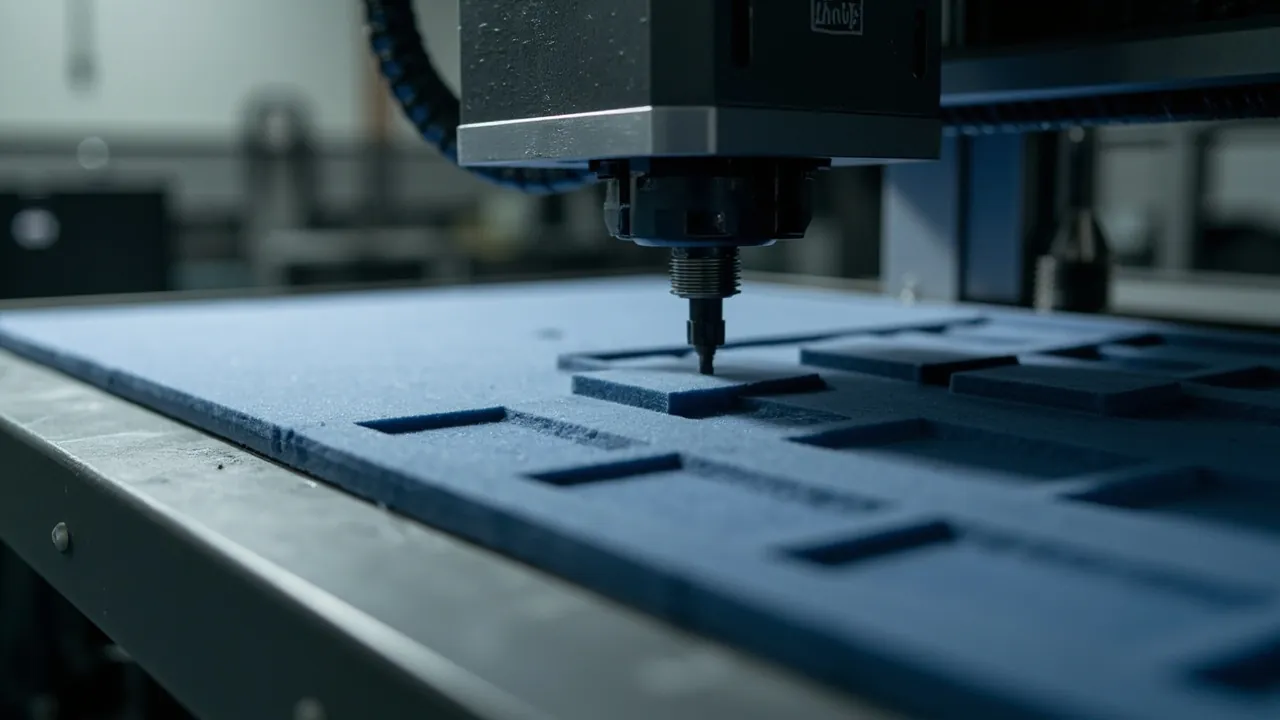
A custom EVA insert follows six steps: measurement, modeling, layer design, CAM programming, CNC cutting, and lamination assembly. What decides success is not cutting accuracy but measurement and layer design. If the 3D data of the item is wrong, or if the layer plan ignores finger access and tolerance allowance, even a five-axis machine will not produce a usable insert. A good insert must do three things: the item must not rattle inside, it must come out without binding, and the closed lid must restrain the item reliably without crushing it.
Many buyers assume insert customization means shipping the item to a factory and letting them carve a cavity around it. In real projects, that ship-the-sample approach produces the highest rework rate. Without accurate data, the factory can only approximate the outline, and for irregular shapes with raised buttons, cable exits, or sharp corners the error compounds to several millimeters, ending either in a rattling item or one that will not fit at all. Multi-layer structures make it worse, because cutting the first layer 1.5 mm too deep forces a recut of the second layer and scraps the set. This guide follows the real delivery sequence: what data to collect, how to set tolerances, how to choose tools and layers, where lamination goes wrong, and which criteria to use at acceptance, with an executable parameter table so engineering and purchasing teams get a production-ready insert on the first sample.
Table of Contents
- 1. Material Premise: EVA Properties and Where It Fits
- 2. Six Categories of Input Data to Gather Before Customization
- 3. Survey and Reverse Engineering: From Scan to Editable Solid
- 4. Layered Insert Design: Margins, Draft, and Finger Pockets
- 5. Tolerances and Fit: How Much Clearance Is Right
- 6. From Model to Toolpath: CAM Programming Essentials
- 7. CNC Cutting Parameters and Tool Selection
- 8. Lamination, Facing, and Hot Press Bonding
- 9. Assembly and Interference Checks
- 10. Sample Validation and Acceptance Criteria
- 11. Cost Structure and Volume Drivers
- 12. How JUNZHJIA Supplies Matching Inserts
- 13. Common Insert Design Failures and How to Prevent Them
- Frequently Asked Questions
- Conclusion and Further Reading
1. Material Premise: EVA Properties and Where It Fits
EVA, or ethylene vinyl acetate copolymer, became the mainstream insert material because it combines three properties at once: a closed-cell structure that does not absorb water, good rebound that resists long-term collapse, and the ability to be cut, bonded, and thermoformed. Hardness is expressed on the Shore A or Shore C scale, and inserts typically sit in the Shore C 25 to 45 range, with densities commonly between 60 and 120 kg/m3. Too soft and the item shifts in use. Too hard and cushioning drops while removal becomes difficult.
Comparing EVA against the usual alternatives makes the selection logic clearer:
| Material | Typical hardness | Rebound and cushioning | Moisture behavior | Cutting and forming | Typical use |
|---|---|---|---|---|---|
| --- | --- | --- | --- | --- | --- |
| EVA | Shore C 25 to 45 | Good rebound, durable | Closed cell, good moisture barrier | Cuts, bonds, thermoforms | Precision instruments, tools, optics |
| PU foam | Shore A 30 to 60 | Soft, excellent cushioning | Mostly open cell, absorbs moisture | Cuts well, bonds poorly | High shock isolation, dry environments |
| EPE foam | Density dependent | Moderate rebound | Closed cell, good moisture barrier | Cuts well, deforms easily | Transit packaging, low cost cushioning |
| XPE foam | Shore C 20 to 35 | Fine cell, slow rebound | Closed cell, good moisture barrier | Excellent thermoforming | Thin liners and facing layers |
| Fabric-faced EVA | Same as EVA | Same as EVA | Same as EVA | Requires hot press or adhesive | Premium inserts needing surface quality |
Note that foam property validation generally references the ASTM D3574 family of methods, covering apparent density, indentation hardness, compression set, and tensile strength. For outdoor or long-term storage applications, light aging assessment per the ISO 4892 series should also be considered. When the insert will sit inside a case containing electrical components, confirm the case flame retardance requirement, such as a UL94 class, together with the insert plan so that the body passes while the insert does not.
2. Six Categories of Input Data to Gather Before Customization
Preparing everything at once is far faster than iterating. Supply these six categories at the inquiry stage.
- Item list: names, quantities, individual dimensions, weights, and center of gravity. Where multiple items share one insert, state the priority and the most common combinations.
- Item 3D data: a STEP or IGES solid model is preferred. If only a physical item exists, confirm whether reverse scanning is acceptable and what scanning tolerance is required.
- Case internal clearance: case model, internal length, width, and height, wall draft, rib heights on the floor, and any raised features around the perimeter.
- Use scenario and handling: opening frequency, whether one-handed removal is needed, whether cable or hose exits must be preserved, and whether separate compartments for manuals or accessories are required.
- Environment and compliance: operating temperature range, contact with oils or solvents, flame retardance requirements, and whether low emission or low odor formulations are needed.
- Appearance and branding: whether fabric facing is required, fabric color and texture, printed or hot stamped logos, and whether colors should distinguish compartments.
Of these, the third category is most often overlooked yet directly decides whether the insert fits at all. Case walls usually carry draft and reinforcement ribs, so designing only to nominal internal dimensions leaves the insert stuck halfway in. The correct approach is to base the design on the maximum internal cavity after sinking, then verify against the physical case.
3. Survey and Reverse Engineering: From Scan to Editable Solid
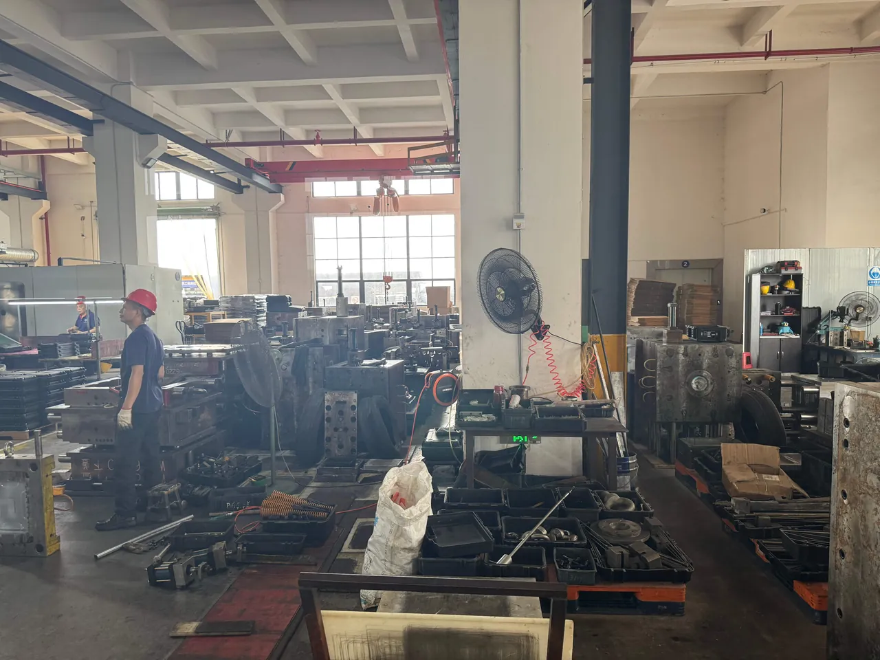
Measurement is the last step where cost should be cut. Three methods exist, ordered by increasing precision and cost.
Manual measurement: calipers and height gauges capture key dimensions. It suits regular shapes needing only simple rectangular cavities. The weakness is that curves, undercuts, and hidden features are hard to express, and results depend heavily on the operator.
3D scanning and reverse engineering: structured light or laser scanners capture point clouds, which are then rebuilt into meshes and solids. This suits irregular shapes with curves and undercuts. The critical quality metrics are scan accuracy and mesh processing. Raw point clouds must be denoised, hole-filled, and aligned before conversion into an editable solid, otherwise toolpaths will follow noise into wavy contours.
Direct modeling from original CAD: if the item is your own product, using design data directly is the most accurate and fastest route, and the only one that guarantees exact conformance with drawings.
Empirically, insert fit achieved through scan-based reverse engineering can be held to roughly plus or minus 0.5 mm, provided the item surface is not reflective or transparent and has no deep narrow holes. Highly reflective metal parts and transparent housings need a matting treatment before scanning, since otherwise the point cloud develops large voids.
Modeling must additionally define three things: item orientation (inverted or tilted), the datum face used as the seating surface, and critical clearance zones (buttons, ports, and labels that must not be compressed). Set any of these wrong and everything downstream is redone.
4. Layered Insert Design: Margins, Draft, and Finger Pockets
Inserts are rarely a single carved layer. A sound plan usually combines a base pad, a middle carrier, and a top facing, each with a distinct function.
Base pad: the lowest layer, providing overall cushioning and leveling. Empirical thickness sits between 10 and 20 mm, and if the case floor has ribs, the pad needs matching relief grooves.
Middle carrier: the main cavity layer carrying the item, with thickness set by item height. If the item is taller than single-layer cutting capacity, split it into two layers and bond them, keeping the bond line away from load-bearing surfaces.
Top facing: a thin upper sheet with openings, used to hold the item down or to give a clean visual surface when the lid opens.
Four design points must be honored:
- Perimeter margin: leave a gap between insert outline and case wall, empirically 0.5 to 2 mm, to absorb dimensional variation in both parts and prevent the insert from bowing under interference.
- Draft: cavity side walls should carry draft, empirically 2 to 5 degrees, which eases item removal and lets the cutter enter, reducing leftover corner material.
- Finger pockets: add a semicircular or rectangular recess beside each item, about half the item height deep and at least 15 mm wide, so the item can be removed even with gloves on.
- Corner relief: a CNC cutter always leaves a radius equal to its tool radius. If the item has square corners, model a matching radius or add a relief groove, otherwise assembly will bind.
For the logic behind layering and compartment combinations, see common internal foam types and how to choose between dividers and foam.
5. Tolerances and Fit: How Much Clearance Is Right
Too tight and assembly is difficult. Too loose and the item rattles. The following empirical ranges can be quoted directly.
| Mating location | Suggested clearance (per side) | Notes |
|---|---|---|
| --- | --- | --- |
| Item to cavity wall, rigid items | 0.5 to 1.0 mm | Balances easy handling with position control |
| Item to cavity wall, soft or fragile items | 1.0 to 2.0 mm | Larger margin, restraint comes from the facing |
| Insert outline to case wall | 0.5 to 2.0 mm | Absorbs variation in both parts |
| Bond line between layers | 0, full adhesive coverage | Prevents local voids that collapse |
| Total height tolerance across cut layers | Plus or minus 1.0 mm | Set by machine and material rebound |
| Finger pocket width | Not less than 15 mm | Ensures gloved operation |
Remember that EVA is elastomeric and rebounds slightly after cutting, so the actual cavity usually ends up marginally smaller than the toolpath dimension. For volume cutting, compensate the toolpath from the first article measurement rather than hand-fitting each piece. If one insert must fit cases from several production batches, design to the median of the case size distribution, not to the maximum or minimum.
6. From Model to Toolpath: CAM Programming Essentials
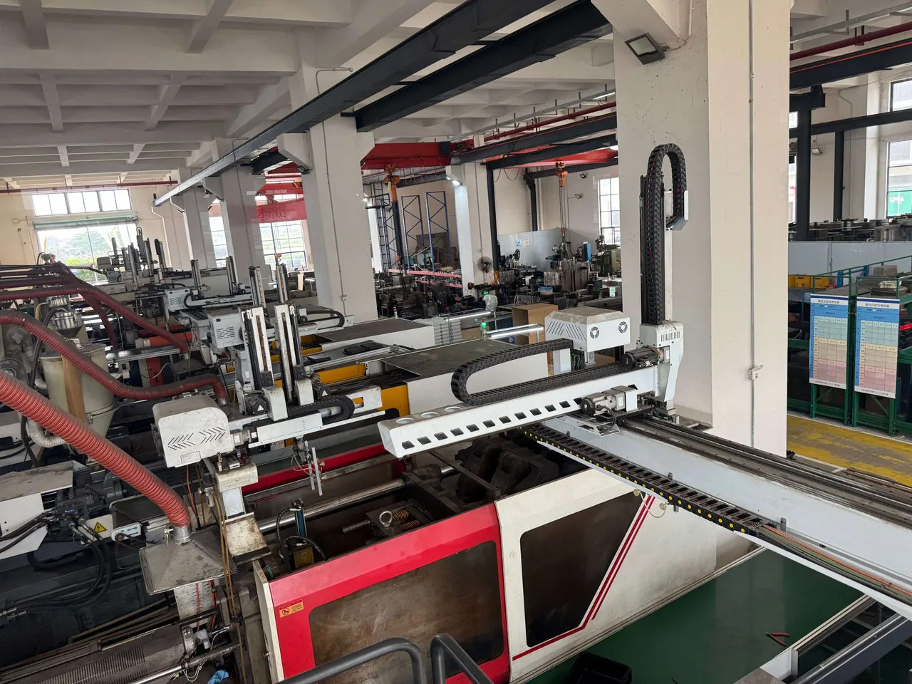
Four conversion steps separate the design model from an executable toolpath.
First, format conversion and inspection. Convert the design model into solid or surface data suitable for CAM, then check for broken faces, overlapping surfaces, and zero-thickness features. Broken faces cause abnormal retracts and even tool crashes.
Second, machining strategy. Insert machining normally splits into roughing and finishing. Roughing uses a large diameter cutter to remove bulk stock quickly, leaving 0.3 to 0.5 mm for finishing. Finishing uses a smaller cutter to trace the contour, holding wall perpendicularity and floor flatness. Deep cavities require stepped depth passes, empirically no deeper per pass than half the cutter diameter.
Third, fixturing and nesting. Large inserts need vacuum fixturing or locating pins to prevent material movement during cutting. Multiple small inserts can be nested on one sheet, but keep enough channel width between parts for the cutter to pass.
Fourth, toolpath verification and simulation. Run collision checks and material removal simulation in software, confirming that deep cavities do not strike the tool holder and that corners are not overcut. For complex geometry, simulation time is far cheaper than a failed first cut.
7. CNC Cutting Parameters and Tool Selection
The table below lists common parameter ranges for insert machining (typical and empirical values; actual settings depend on material batch and machine condition).
| Operation | Tool form | Common diameter | Spindle speed tendency | Feed tendency | Purpose |
|---|---|---|---|---|---|
| --- | --- | --- | --- | --- | --- |
| Outer contour roughing | Two-flute end mill | 6 to 12 mm | Medium high | Medium high | Fast removal around the outline |
| Cavity roughing | Two or three flute end mill | 6 to 10 mm | Medium | Medium | Stepped passes with finishing allowance |
| Contour finishing | Two-flute end mill | 3 to 6 mm | High | Medium | Wall perpendicularity and surface quality |
| Corner cleanup | Flat or ball nose | 1 to 3 mm | High | Low | Square corners and narrow slots |
| Facing sheet openings | Single flute or oscillating knife | 1 to 3 mm | High | Medium high | Thin sheet, minimizes distortion |
| Depth controlled cutting | Oscillating or CNC knife | Not applicable | Not applicable | Medium | Cuts to a set depth without through cutting |
Three details are commonly missed:
- Chip evacuation: EVA chips are light and static-prone, so adequate dust extraction and air blow are mandatory. Otherwise chips are recirculated into the cavity and scratch the walls.
- Cooling: EVA is usually dry cut or run with minimal lubrication. Flood coolant causes the material to absorb liquid and swell.
- Tool wear: EVA wears cutting edges abrasively, so set a tool life in volume production and change tools by cut length or piece count rather than waiting for visible burrs.
8. Lamination, Facing, and Hot Press Bonding
Layered inserts must be bonded into one unit after cutting, and this step decides appearance life.
Adhesive bonding: use an adhesive suited to foam, apply evenly without starved areas, then press and hold until initial cure. The usual failures are edge lift and center blistering. Edge lift comes from insufficient adhesive at the perimeter, blistering from solvent not fully flashing off.
Hot press bonding: temperature and pressure combine to bond layers while embossing curves and patterns. The critical controls are the upper temperature limit and dwell time, because excessive heat makes the EVA surface glossy, shrink, or degrade.
Fabric facing: laminating fabric, flock, or non-slip material onto EVA improves texture and feel. After lamination, check for wrinkling, edge delamination, and any effect on cavity fit, since the facing thickness usually has to be deducted from cavity clearance.
If the insert needs a printed logo or marking, plan surface branding at the same time. Durability and applicable surfaces vary noticeably between marking processes, as covered in five branding methods for protective cases.
9. Assembly and Interference Checks
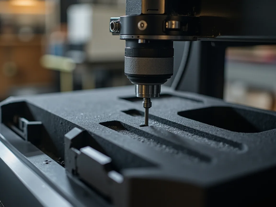
A finished insert is not a delivered insert. Assembly validation cannot be skipped. The checklist:
- Empty fit test: install the insert alone and confirm the outline seats fully with no bowing or lifted edges, and no relative sliding between layers.
- Full load test: load the maximum configuration and confirm no crushing, no floating items, and no item-to-item contact.
- Open and close test: cycle the lid repeatedly and confirm the facing does not scrape item surfaces, and that latch pressure is not transmitted through the facing onto delicate parts.
- Handling test: simulate gloved operation, removing and returning each item while recording any binding.
- Cable and port test: where items carry cables or connectors, confirm the exit paths are unobstructed and not pinched.
- Drop and vibration spot checks: at full case level, verify to the target standard that the worst-case orientation produces no displacement or damage.
For precision instruments or optical equipment, run a full case ingress protection check after assembly to confirm that adding the insert has not weakened sealing performance. Relevant criteria appear in understanding the IP67 rating.
10. Sample Validation and Acceptance Criteria
First article and volume acceptance should combine objective data with subjective judgment.
Objective items: total insert thickness, cavity position and dimensions, wall perpendicularity, sampled bond strength between layers, and sampled material density and hardness. Sample sizes follow batch scale, using standard count-based sampling practice.
Subjective items: surface scratches, adhesive residue, burn marks, color conformance to the approved sample, fabric wrinkling, and odor within acceptable limits. For appearance-sensitive projects, produce and sign a golden sample as the baseline for later batches.
Empirically, the three most common return reasons for insert products are poor dimensional fit, causing either rattling or inability to fit, appearance defects such as scratches and adhesive residue, and delamination between layers. Suppressing these three at the first article stage noticeably lowers the abnormality rate in volume production.
11. Cost Structure and Volume Drivers
Insert cost splits into four blocks: material, programming and sampling, cutting time, and lamination with post-processing.
| Cost item | Main drivers | Ways to reduce |
|---|---|---|
| --- | --- | --- |
| Material | Material type, density, layer count, facing material | Optimize layer count, avoid overdesign |
| Programming and sampling | Structural complexity, scanning needs, sample rounds | Provide original CAD data wherever possible |
| Cutting time | Total cavity length, depth, tool diameter, corner count | Simplify contours, reduce narrow slots and sharp corners |
| Lamination and post-processing | Layer count, facing method, printing or hot stamping | Reduce layers, standardize facing process |
Volume mainly affects amortization of programming and sampling cost, plus material utilization. Tighter nesting lowers material cost per piece, but over-tight nesting compresses tool channels, which raises cutting time and breakage risk. Balance the two.
12. How JUNZHJIA Supplies Matching Inserts
JUNZHJIA, manufactured by KeXin New Materials (Guangdong) Co., Ltd. at its Zhongshan facility, supplies custom insert programs across protective cases, toolboxes, military weapon cases, and waterproof junction boxes. The standard workflow is: the customer provides item 3D data or physical items, and the factory completes measurement and modeling, layer plan design, toolpath programming, and CNC cutting, with lamination, facing, and marking available as needed. When the customer also purchases the case, insert and case are validated together in the same delivery batch, removing ambiguity about interface responsibility. For projects with flame retardance or environmental requirements, supporting material documentation can be provided on request. Specific fit tolerances, sample rounds, and volume thresholds are assessed against item complexity and case model.
13. Common Insert Design Failures and How to Prevent Them
Most insert problems are predictable, and each traces back to a decision made early rather than to cutting quality. The table below maps the seven failures seen most often to their root causes and prevention measures.
| Failure | What the user experiences | Root cause | Prevention |
|---|---|---|---|
| --- | --- | --- | --- |
| Items rattle in transit | Item shifts and strikes the cavity wall | Clearance too generous for the item weight, facing too thin | Tighten side clearance to 0.5 to 1.0 mm and increase facing thickness |
| Item will not come out | Binding on removal, especially with gloves | No finger pocket, excessive draft omitted, square corners | Add finger pockets at least 15 mm wide, apply 2 to 5 degrees of draft |
| Insert bows after assembly | Lid will not close flush, gasket compresses unevenly | Perimeter margin too small, insert pressed against case ribs | Increase margin to 0.5 to 2.0 mm and relieve the insert at rib positions |
| Delamination over time | Layers separate at the edges after months of use | Insufficient adhesive at the perimeter, solvent not flashed off | Full perimeter coverage, controlled flash-off, press and hold to initial cure |
| Wavy cavity contours | Side walls are not straight, item fits loosely in places | Point cloud noise not removed before solid conversion | Denoise, fill holes, and align the scan before modeling |
| Cavity too shallow at the bottom | Item sits above the intended depth | Layer thickness cut without accounting for material rebound | Compensate the toolpath from first article measurement |
| Fabric facing wrinkles | Visible creases or lifting at edges | Lamination temperature or pressure inconsistent | Lock press parameters and inspect after each lamination run |
Three of these failures deserve a closer look because they are expensive to fix after tooling exists.
The first is clearance chosen by feel rather than by item weight. A soft insert with generous clearance feels comfortable during a bench test, because the item slides in easily and the facing closes over it. In transit, however, the item accelerates inside the clearance and strikes the cavity wall repeatedly. The correct approach is to size clearance to item mass and expected shock level, then rely on the facing for restraint rather than on a tight cavity alone. Where items are heavy, a combination of tight side clearance and a firm facing outperforms a loose cavity with deep foam.
The second is ignoring the case's internal ribs. Case floors and walls commonly carry reinforcement ribs that project several millimeters inward. An insert designed only to the nominal internal envelope will sit on top of those ribs, lift the lid line, and compress the gasket unevenly. In cases carrying an ingress protection claim, that alone can cause a leak. Always obtain a cross-section or physical sample of the case interior and model reliefs at every rib location.
The third is treating the first article as a formality. Because inserts are elastomeric, the first article is the only reliable source of true cavity dimensions. Measure it properly, record the deviation from the toolpath, and apply a single global compensation before cutting the batch. Hand-fitting individual pieces hides the underlying error and guarantees that the next order repeats it.
A useful discipline is to produce a short design review record before cutting anything: item weight and shock expectation, chosen clearance and why, rib relief locations, finger pocket positions, layer bond lines, and the expected first article measurement points. The record takes minutes to prepare and typically prevents the majority of rework.
Frequently Asked Questions
Q: Do I need to send physical items to customize an EVA insert?
A: Not necessarily, but sending physical items is usually the more efficient choice. The ideal input is a STEP or IGES solid model of the item, which allows direct modeling at the highest accuracy with no scanning error. If only a physical item exists, 3D scanning and reverse engineering are used, and empirical scan accuracy can reach roughly plus or minus 0.5 mm, provided the surface is not reflective or transparent and has no deep narrow holes. Highly reflective metal parts and transparent housings need matting before scanning, otherwise the point cloud develops large voids. If the item has a regular shape and needs only simple rectangular cavities, providing key dimensions is also workable and the factory can design from experience. Sending only photos or three views is not recommended, because curves and undercuts cannot be expressed and rework becomes likely.
Q: How hard should the EVA material be for an insert?
A: Inserts commonly use the Shore C 25 to 45 range, with densities typically between 60 and 120 kg/m3. Choose based on item weight and handling. Heavier items should use a firmer grade to avoid collapse and deformation under sustained load. Precision or fragile items should use a softer grade for better cushioning. When one insert must carry a heavy item and protect a light one, use different hardnesses across layers, for example a firmer base pad for support and a softer facing for restraint. Foam property validation generally references the ASTM D3574 family, covering apparent density, indentation hardness, compression set, and tensile strength.
Q: What tolerances should I set for insert cavities?
A: Set values per mating location rather than one global number. Between rigid items and cavity walls, allow 0.5 to 1.0 mm per side to balance easy handling with position control. For soft or fragile items, allow 1.0 to 2.0 mm and rely on the facing for restraint. Between insert outline and case wall, allow 0.5 to 2.0 mm to absorb variation in both parts. Keep total height tolerance across cut layers within plus or minus 1.0 mm. Remember that EVA is elastomeric and rebounds after cutting, so the actual cavity ends up slightly smaller than the toolpath dimension. Compensate the toolpath from the first article measurement rather than hand-fitting each piece, and if one insert must fit several case batches, design to the median of the size distribution.
Q: Which cutting tools are appropriate for CNC insert machining?
A: Assign tools by operation. Outer contour roughing can use a 6 to 12 mm two-flute end mill for fast stock removal. Cavity roughing uses a 6 to 10 mm two or three flute end mill in stepped passes, empirically no deeper per pass than half the cutter diameter, leaving 0.3 to 0.5 mm for finishing. Contour finishing switches to a 3 to 6 mm cutter to hold wall perpendicularity. Corner cleanup uses a 1 to 3 mm flat or ball nose cutter. Facing sheet openings are best cut with an oscillating knife or single flute cutter to reduce distortion. Three process details are easily missed: EVA chips are light and static-prone so adequate dust extraction and air blow are essential; cutting is usually dry or with minimal lubrication because flood coolant swells the material; and tool wear is abrasive, so change tools by cut length or piece count.
Q: Why can't the layer plan be decided arbitrarily?
A: Layering defines both function and cost, and arbitrary layering causes two kinds of problems. Functionally, if the middle carrier is cut too deep the item loses support area and shifts under impact; if the facing is too thin clamping force is insufficient and the item bounces in transit; and if the bond line falls exactly on a load-bearing surface, delamination risk rises over time. On cost, every added layer means another cut and another bonding operation, and material utilization drops. A sound approach is a base pad providing overall cushioning and leveling with an empirical thickness of 10 to 20 mm, a middle carrier holding the main cavities with thickness set by item height and split into two bonded layers when taller than single-layer capacity, and a top facing that holds items down and presents a clean opening.
Q: How long does it take to get an insert sample?
A: The timeline depends on data completeness, structural complexity, and sample rounds, so no fixed figure applies. It can be broken down into data preparation and confirmation, modeling and layer plan design, toolpath programming, first article cutting, and assembly validation with correction. The most common delays come from data preparation and plan confirmation, particularly projects needing scan-based reverse engineering or internal approval of item orientation. The fastest way to shorten the cycle is to provide original solid models, deliver all six input categories at once, and settle item orientation and critical clearance zones up front. For projects where multiple items share one insert, state the priority and common combinations early to avoid repeated plan changes.
Q: Can the insert be validated together with the case?
A: Yes, and doing so is strongly recommended. The insert and the case are two independent dimensional systems made on different equipment and processes. Individually acceptable parts can still interfere or leave gaps when assembled together. When both come from one supplier, assembly validation and full case spot checks can be completed within the same batch, interface responsibility stays clear, and troubleshooting never has to cross two suppliers. JUNZHJIA supplies both cases and inserts across protective cases, toolboxes, military weapon cases, and waterproof junction boxes, and can complete measurement, cutting, lamination, and marking in parallel, with ingress protection and drop spot checks performed at full case level.
Q: Will an EVA insert collapse over time?
A: EVA's closed-cell structure and rebound behavior make it more resistant to collapse than most open-cell foams, but collapse can still occur in three situations. First, sustained compression, such as a lid kept latched for long periods with the item pressing on one spot, which produces compression set. Second, choosing a grade that is too soft or too low in density to carry a heavy item. Third, high temperature accelerating material softening. To reduce risk, match hardness and density to item weight at the design stage, avoid sustained local over-compression, and add a support layer where loads concentrate. In warmer environments, evaluate the material using the compression set and related aging methods in ASTM D3574, and consider light aging performance per the ISO 4892 series.
Conclusion and Further Reading
The heart of EVA insert customization is not the cutting machine but the rigor of measurement and layer design. Gather all six data categories at once, replace vague descriptions with solid models, and lock down orientation, datum face, and critical clearance zones before anything else. Tolerances should be set per mating location, with adequate perimeter margin and draft and non-negotiable finger pockets. Cutting parameters must match tool diameter and material thickness, with chip evacuation and tool life managed as routine. Lamination and facing need controlled temperature and even adhesive coverage. Finish with the six validations: empty fit, full load, open and close, handling, cables, and full case spot checks. Once that sequence is complete, rework and volume abnormality rates drop noticeably. JUNZHJIA accepts insert programs based on customer 3D data or physical items and validates them together with the case, with scope and sample rounds confirmed against item complexity and case model.
Further Reading