

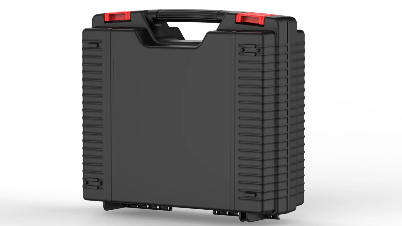
The crosshead and the take-up stand on a cable extrusion line have opposite characters. The crosshead is precision work: the distributor cone, inner and outer dies and the die holder hold concentricity in the 0.02–0.05 mm range, the flow channel is polished to Ra 0.2–0.4 μm, and several ceramic or mica heater bands wrap the body. Press an indentation into that flow face, or crack a heater band internally, and the result appears immediately as eccentricity and bamboo-like surface defects on the cable. The take-up stand is heavy work: welded frames, tension wheels, reel shafts and centre tapers, tension cylinders and load sensors, with individual parts reaching several hundred kilograms. What transport threatens there is a twisted frame, lost coaxial alignment between shaft and bearing housing, and bearings dented by impact. One packaging logic has to solve both the precision problem and the heavy-load problem.
JUNZHIJIA builds its protection principle for cable extrusion components on three commitments: place precision flow faces and coaxial fits in separate soft compartments where they carry no structural duty, restrain heavy frames and long shafts mechanically so torque and deflection are not carried into the destination, and hold humidity low enough that polished steel does not pit. The scheme works when three sets of numbers survive the journey: the feeler reading on the crosshead flow face, the insulation resistance of the heater bands, and the diagonal length difference of the take-up frame. This article works through crosshead flow paths, heater bands, take-up stands and long shafts, and sets out packaging parameters and acceptance values that can be measured and repeated.
Table of Contents
- Preserving Flow-Channel Accuracy in Cable Extrusion Crossheads
- Storing the Distributor Cone and Inner/Outer Dies as a Coaxial Set
- Ceramic and Mica Heater Bands: Cracking Risk and Vibration-Safe Compartments
- Flange Bolts and Seal Faces on the Crosshead: Rust-Free Matched Storage
- Impact Protection for Tension-Wheel Bearings on Take-up Stands
- Concentricity Protection for Reel Shafts and Centre Taper Faces
- Divided Storage for Tension Cylinders and Load Sensors
- Restraining Welded Take-up Frames Against Twist Deformation
- Clean Compartments for Slip Rings and Carbon Brush Assemblies
- Deflection Control and Multi-Point Support for Long Take-up Shafts
- Anti-Rust Strategy for Crosshead Flow Faces in Salt-Fog and Humidity
- Pre-Assembly Checklists and On-Site Counting Routine
- Frequently Asked Questions FAQ
- Conclusion and Related Reading
Preserving Flow-Channel Accuracy in Cable Extrusion Crossheads
The flow channel of a cable crosshead — whether a right-angle, offset or semi-squeeze design — is bounded by the distributor cone, the die seat, the die and the adjusting ring. From the feed port to the die exit it must stay a smooth transition with no step, pit or stagnation zone. Once the channel carries an indentation, melt forms a vortex and dwells there, degrades over a long run, and eventually appears on the insulation surface as a periodic raised band or discoloured patch. Such defects usually surface only at final inspection, and tracing them means stopping the whole line and stripping the head, at a cost far beyond the price of packaging.
The governing rule is that the flow face never enters the load path. First, the crosshead should be packed either in its assembled state or in assembly order, and the flow face must never rest directly on the case floor, on a spacer block or on a fastener. Second, a continuous soft contact layer — non-woven or flocked composite, 1–2 mm thick — must sit between the head and the liner, with no butt joint falling inside the flow-face area. Third, the head should bear on its housing or die seat, supported by a liner milled to the housing outline, rather than on the flow face or on adjusting bolts.
Orient the head with the die pointing up or to the side, so the full weight never presses on the die lip. For small heads with a thin lip, fit a soft lip guard whose bore is slightly larger than the lip and whose outside diameter stays within the head envelope, so the guard itself never becomes a load point. Where the head carries adjusting bolts, cover the bolt heads with foam collars and cut clearance pockets into the liner, so vibration cannot drive a bolt head into a neighbouring part.
| Crosshead area | Main risk | Consequence | Packing measure |
|---|---|---|---|
| --- | --- | --- | --- |
| Flow face | Indentation, scratching | Stagnant resin, insulation defects | Continuous soft layer, never a support |
| Die lip | Impact, rolled edge | Diameter and roundness out of tolerance | Soft lip guard ring |
| Distributor cone | Cone-face damage | Uneven melt distribution | Dedicated cone sleeve plus locating seat |
| Adjusting bolts | Deformation by impact | Eccentricity adjustment lost | Foam collar plus clearance pocket |
| Flange seal face | Corrosion, scratching | Joint leakage | VCI film plus non-woven separation |
Storing the Distributor Cone and Inner/Outer Dies as a Coaxial Set
The concentricity of the distributor cone with the inner and outer dies sets the eccentricity of the extruded layer. These parts locate on tapers or cylindrical fits and clamp on end faces, and they leave the factory lapped or hatched as a matched set. The classic transport injury is local taper damage: a taper has a small contact area and carries high unit pressure, so a single hard point acted on repeatedly by vibration presses a ring-shaped dent into it, the fit no longer seats properly, and concentricity drifts.
Pack them upright and coaxial with the taper floating. Support the set on a soft ring matched to the large-end diameter so the taper touches nothing hard, and locate it axially on an end face or shoulder. For a slender inner die, add a second soft ring at mid-length so the overhang is not excessive. Matched distributor cones and dies should travel side by side in the same pocket, laid out in assembly order, with the match number and relative orientation printed on the liner. Where separate pockets are unavoidable, the numbers on the two pockets must agree exactly, or parts will be cross-assembled on site.
Cleanliness is not optional either. In service the channel collects resin and carbonised deposits, and PVC and halogen-free flame-retardant compounds in particular release acidic species under warm humid conditions. After stripping the head, purge with a dedicated cleaning compound, wipe with a neutral cleaner and a soft cloth, and never use wire brushes or abrasive paper. Apply a thin volatile corrosion inhibitor immediately and wrap the taper in non-woven. Taper and cylindrical fits follow the same logic as Bearing and Gearbox Component Cases: Transport Protection for Precision Fits — the contact surface never carries load, and cleanliness matters as much as the separating layer.
Ceramic and Mica Heater Bands: Cracking Risk and Vibration-Safe Compartments
A cable crosshead carries three to eight heater bands, usually ceramic, mica or cast-aluminium types. Ceramic and mica bands contain brittle insulation around the resistance wire, so a drop or a local squeeze can crack the interior while the shell still looks perfect. On power-up the band heats slowly, overheats locally, or oscillates widely. Cable extrusion is extremely sensitive to head-zone temperature: a ±5 °C swing in head temperature is enough to roughen the insulation surface and push eccentricity out of tolerance.
Three rules cover the bands: the bore never carries load, the lead is never pulled, and the winding never rattles. Support each band on a cylindrical mandrel matched to its bore so it sits on the mandrel instead of being laid flat and flattened. Coil the lead separately, secure it with hook-and-loop tape at a bend radius of at least ten times the cable diameter, and protect the joint with heat-shrink. Fill the small gap between band and mandrel with thin EPE or EVA so the band cannot bounce in transit.
Place the bands above any heavy metal parts in the case and put a rigid divider between them. Where one case holds bands of different bore and wattage, store them in separate compartments and screen-print size, wattage and voltage on each divider, so nobody installs a mismatched band and creates a local hot spot. On arrival, measure insulation resistance with a megohmmeter and record it against the dispatch value; that reading is the only dependable way to find internal cracking that leaves no external mark.
Flange Bolts and Seal Faces on the Crosshead: Rust-Free Matched Storage
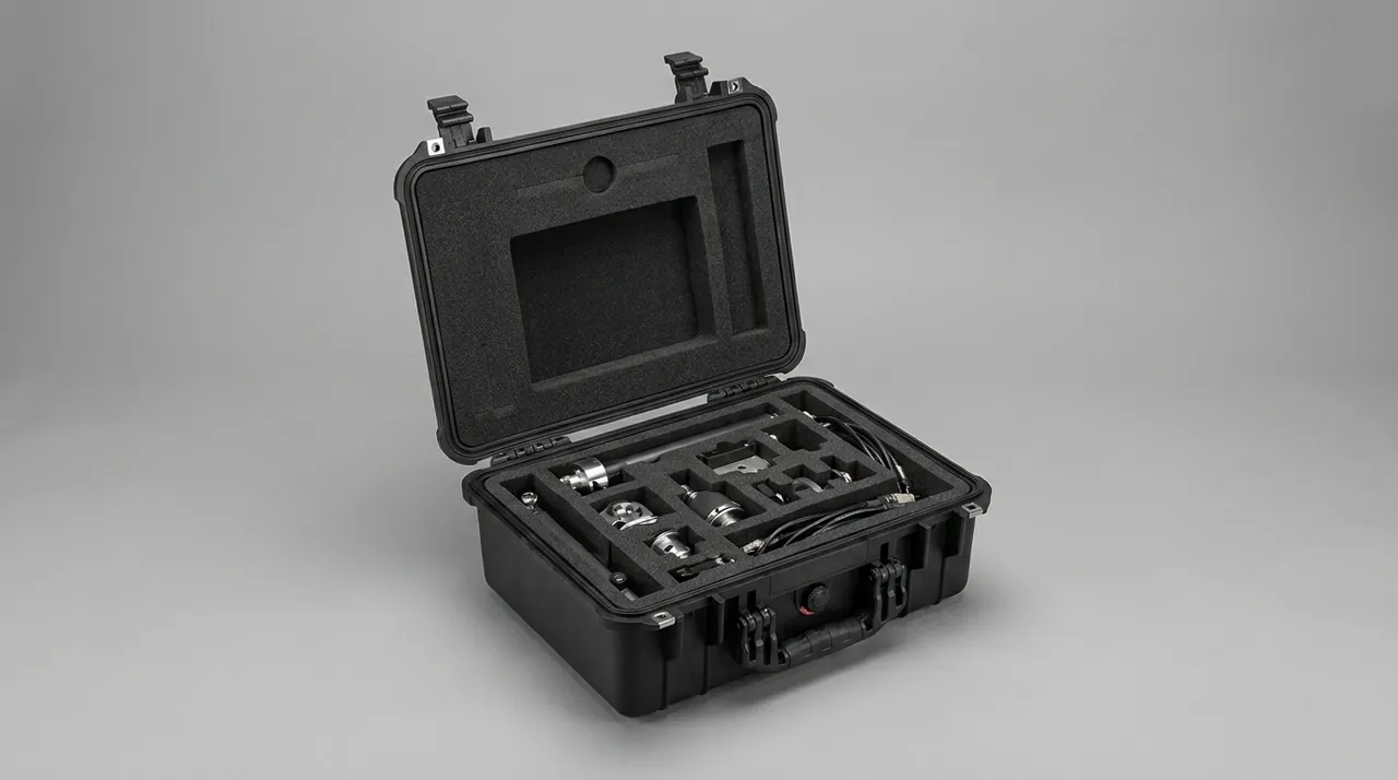
The crosshead bolts to the extruder barrel through a flange, sealed by metal-to-metal contact, an O-ring or a combined arrangement. Once the flange face corrodes or is scratched, the joint leaks melt, and melt leakage does more than make a mess: head pressure becomes unstable and the extruded layer loses thickness consistency. Protecting the flange face is a three-step sequence — clean, isolate, dry.
Cleaning means removing resin, old sealant and oil completely, then wiping with anhydrous ethanol or a dedicated cleaner and letting it flash off fully. Isolation means a PE protection film or a volatile corrosion inhibitor plus non-woven over the face, with the film edge overhanging the flange by 10–20 mm so it can be gripped and peeled. Drying means desiccant inside the case to hold relative humidity below 40 %RH, with an indicator card on the inside of the lid.
Flange bolts are easily lost and are often high-strength, non-standard lengths. Put each head's bolts in a divided tray, segregated by size, with the tightening torque and tightening sequence printed on the lid. If the bolts stay fitted to the head, run them in but do not torque them down: preload relaxes under transport vibration and then loads the seal face cyclically. Cover the bolt heads with foam collars so they cannot mark adjacent parts or the case wall. Seal elements such as O-rings and gaskets travel separately in light-proof moisture-barrier bags, labelled with size and material; Case Gasket and O-Ring Materials: Selection and Service Life covers the material comparison.
Impact Protection for Tension-Wheel Bearings on Take-up Stands
The tension wheel on a take-up stand is a classic heavy part on precision bearings: a steel or aluminium wheel 300–800 mm in diameter on deep-groove ball or self-aligning roller bearings. What destroys those bearings is not sustained vibration but instantaneous shock. Shock presses false brinelling marks into raceways and rolling elements. At unpacking the bearing turns freely and looks perfect, but once load and speed come up, every ball crossing a dent produces an impulse, heard as periodic noise and felt as temperature rise, most obviously at high line speed.
The key to preventing brinelling is limiting acceleration rather than displacement. Under the wheel, use high-density EVA or polyurethane elastomer blocks sized by mass — roughly 30–50 mm of thickness per 100 kg — and fit axial stops at the shaft ends so the bearing never takes axial shock. For detachable wheels, pack the wheel and the shaft separately: cradle the shaft in a V-block, sleeve the bearing journals, and the shock path no longer runs through the raceways.
Eliminate hard-to-hard contact paths inside the case as well. No steel part should touch another steel part without a soft separator between them, and straps crossing a wheel rim need soft pads, otherwise the webbing polishes a bright band into the rim under vibration. Where several tension wheels ship together, arrange them in layers separated by rigid dividers, heavy parts low and light parts high, and never fill the gaps with loose foam beads: the beads settle under vibration and the upper parts lose constraint.
Concentricity Protection for Reel Shafts and Centre Taper Faces
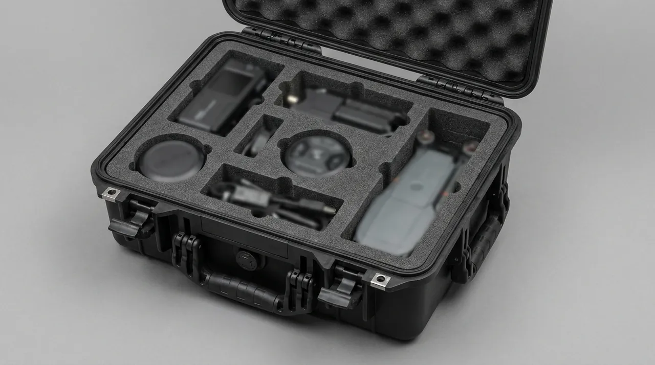
Reel shafts and centre tapers mate on a taper or on a keyed cylinder, and their job is to centre the reel accurately and transmit torque. A damaged taper sets the reel spinning with a small eccentricity, which at high take-up speed produces vibration, uneven lay, and scuffing on the cable surface; in severe cases reel runout exceeds tolerance and the whole assembly is replaced. Such damage is usually invisible during low-speed trials and only shows up near rated line speed.
Protect the taper by keeping it clear of everything, locating on the end face, and wrapping the keyway. Keep the taper clear means the taper touches no liner or spacer directly; it is covered by a soft cone sleeve matched to its angle, 3–5 mm wall thickness, with a smooth jointless inner surface. Locating on the end face means the axial position of the shaft is set by an end face or shoulder, not by wedging the taper. Wrapping the keyway means sleeving the keyed shaft end in non-woven before it goes into its locating block, so the key edges neither score the liner nor create a hard point.
Long shafts normally travel horizontally, with support points set by diameter and length. For a reel shaft up to 1500 mm long and 80 mm in diameter, use at least three supports and hold the maximum free span within 15–20 times the diameter. Longer take-up shafts need an extra support every 600–800 mm, with the height difference between neighbouring supports no more than 0.5 mm. V-blocks or half-round cradles faced with IXPE or EVA are preferred; a flat pad contacts along a line and eventually prints a mark into the shaft.
Divided Storage for Tension Cylinders and Load Sensors
Tension control on a take-up stand uses cylinders or hydro-pneumatic dampers, load sensors, pressure regulating valves and linkage. These parts are small, precise, sensitive to contamination and installed in awkward places, so damage discovered on site means stripping the whole tension arm. Cylinder piston rods are hard-chrome plated and polished, and any impact breaks the plating and wears the seal early; strain-gauge load sensors drift at zero when overloaded or side-loaded.
Remove cylinders and sensors from the tension arm and store them in separate compartments. Place a cylinder with the rod horizontal or pointing down, fit a protective cap over the rod end, and fit soft stops at both ends of the body so the piston cannot shuttle during transport. On long-stroke cylinders, insert a wooden or EVA travel block to lock the piston at mid-stroke. Store load sensors in their own compartment, never sharing with metal parts, seal the terminals in a moisture-barrier bag, and label the zero-calibration status and calibration date.
Pressure regulating valves and precision fittings are a high-risk small-part group. Use a transparent divided tray, one part per compartment, with matching numbers on the inside of the lid, and fix the tray on the upper layer of the case over a soft pad. Where a project includes several fitting sizes, the label must carry both thread size and material so nobody cross-fits a part and creates a leak. Small mechanical items such as latches follow a similar selection logic, described in Case Latch Selection: Pull Strength, Cycle Life and Anti-Opening Design.
Restraining Welded Take-up Frames Against Twist Deformation
A welded take-up frame is large with an uneven stiffness distribution, and the damage it fears most is a twist that leaves a permanent angular distortion. The most direct indicator is the diagonal length difference: measure the two diagonals across the frame corners before dispatch and repeat after transport, and a difference above 3 mm usually means angular distortion has occurred. Once the frame twists, reel-seat levelness and column parallelism both suffer, and the reel surges axially during take-up.
Three points govern the restraint scheme. First, support points must land on structural nodes — column roots, beam-to-column junctions — never mid-span, because a mid-span support lets the frame deflect locally under its own weight. Second, tie the frame to the case with adjustable struts or timber blocks so the load path closes as case–strut–frame, instead of relying on strap tension to hold the frame in shape. Third, use straps only to limit horizontal movement and prevent tipping; they are not torsional members, because webbing stiffness is a fraction of the welded frame's and contributes nothing against twist.
For frames that can be dismantled, pack column, beam, reel seat and tension arm separately with assembly numbers preserved. More cases are needed, but the twist risk drops sharply. For a one-piece frame taller than 1.5 m, evaluate vertical packing with side bracing, and give the vertical arrangement a continuous load-bearing base rather than four corner contacts.
Clean Compartments for Slip Rings and Carbon Brush Assemblies
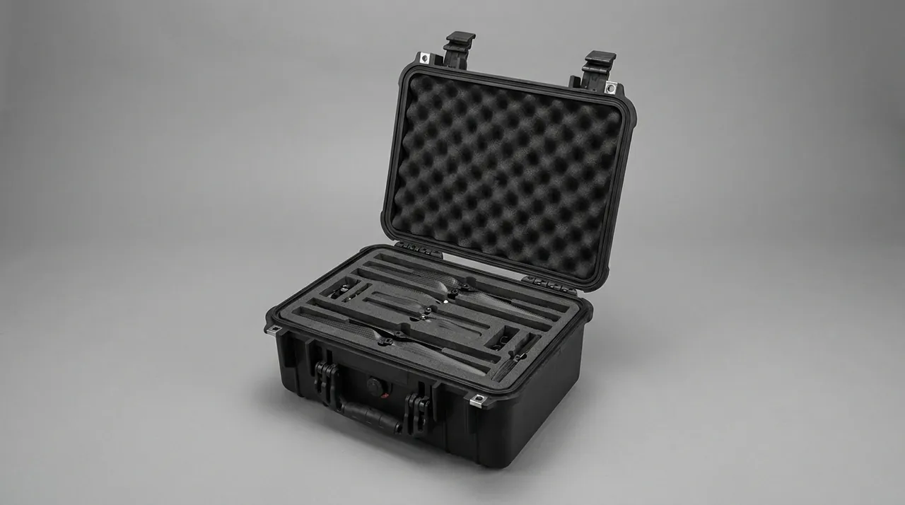
Continuous take-up equipment — take-up sections of stranding machines and some disc-type stands — often carries a slip ring to pass signals or power across a rotating joint. The brush-to-ring contact inside is precise, closely gapped and highly sensitive to dust and grease. Dust entering the contact surface causes intermittent signals and arcing, and long-term arcing accelerates ring wear; axial shock can displace or break the brushes.
Treat a slip ring as an independent precision item. Plug every cable entry and vent, slide it into an antistatic bag, evacuate the air, and place it in an EVA pocket matched to its outline. Pack carbon brush assemblies separately, protect each brush lead with foam tubing, and never bend a lead through a right angle. Restrain the slip ring axially and radially — never by strap pressure alone, because a strap slackens in transit and the ring then rolls inside its pocket. Where the ring carries encoder components, handle it to precision-electronics standards, add desiccant, and mark the case fragile, humidity-sensitive and magnetic-sensitive.
Protect the mounting interface as well. Plug locating pin holes with soft bungs so dust cannot enter, apply a PE film to the flange face, and list the film removal step on the packing list. On arrival, measure insulation resistance and contact resistance before deciding to install; if a reading is abnormal, photograph the fault with the packaging still intact and notify the supplier.
Deflection Control and Multi-Point Support for Long Take-up Shafts
The long take-up shaft is the hardest part in the case: 2–4 m long, with mass concentrated at the middle or one end, and ends carrying tapers, keyways or couplings. Two failures dominate: permanent bending from excessive mid-span deflection, and taper damage from poor end support. Deflection shows at unpacking as a slight sag at mid-length, measurable with a straight edge or a dial indicator. Once bending exceeds the allowance, reel runout is out of tolerance and cannot be corrected on site.
Control deflection by controlling the maximum free span, again held within 15–20 times the shaft diameter. For stepped shafts carrying a reel seat, use the smallest section diameter as the calculation basis, or the deflection estimate will be optimistic. Set the number of supports from the span, and keep the height difference between adjacent supports within 0.5 mm. Cradles must contact the cylindrical section only — never a taper, keyway or shoulder fillet, because all three are stress raisers.
End protection uses three layers: a soft cone sleeve on the taper, a soft end cap on the shaft end, and an axial end stop for location. Place straps over support points with soft pads between webbing and shaft. Any shaft longer than 2.5 m needs at least three straps and longitudinal stops at both ends of the case, so emergency braking cannot drive the shaft into the wall. Where a long shaft must share a case with other heavy parts, it occupies the bottom layer on its own, and the layer above is carried on a rigid divider so no point load reaches the shaft.
Anti-Rust Strategy for Crosshead Flow Faces in Salt-Fog and Humidity
Cable extrusion lines are often exported to coastal or tropical regions, where sea freight and open port storage bring salt fog and high humidity together. Crossheads are usually alloy or stainless steel, and a polished flow face has high surface energy and is extremely sensitive to chloride. Measured against a neutral salt-spray test to GB/T 10125 or ISO 9227, an unprotected polished face can pit within tens of hours; inside a sealed case with desiccant and inhibitor, the usable period under the same conditions extends several times over.
The strategy has three layers. Surface treatment: after cleaning and drying, spray a volatile corrosion inhibitor on flow faces and flange faces to a 1–3 μm film — thicker films attract dust — and use a dedicated stainless-steel protectant rather than chloride-bearing solvents. Environmental control: hold relative humidity below 40 %RH with silica gel or molecular sieve at 2–3 g/L of net volume, monitored by an indicator card on the lid. Packaging seal: design the case to IP65 or IP67, hold gasket compression at 25–35 %, and fit a pressure-equalisation valve to absorb the differential created by temperature swings. Gaskets age too, and Case Seal Ageing: Causes, Diagnosis and Replacement Intervals sets out how to judge and when to replace them.
Note that salt-spray results and real transport exposure are not the same thing. Case performance should be confirmed by a transport test and an arrival inspection rather than inferred from a laboratory report. For export projects, place a temperature and humidity logger in the case with a 10-minute sampling interval as objective evidence for acceptance and claims. If the goods will sit in an open port for more than two weeks, add an outer rain cover and stand the case on a pallet so the base never rests on standing water.
Pre-Assembly Checklists and On-Site Counting Routine
Crossheads and take-up stands contain many parts in many sizes, so a full pre-assembly and checklist review must happen before dispatch; a missing part found on site costs far more in downtime than the packaging itself. Work this way: first do a trial assembly in the assembly area, in assembly order but without final torque or sealant, confirming that every part is present, that match numbers agree and that seal sizes are correct. Then dismantle and pack part by part, with a second person verifying and ticking off each item as it goes in. Photograph the loaded case and file the image with the packing list.
Build the packing list with eight columns: case number, pocket number, part name, drawing number, match number, quantity, unit weight and protection applied. Produce the list in Chinese and English, ship one copy and archive one electronically. Export projects should add material and surface-treatment columns for customs and incoming inspection. Paste a layout drawing inside the lid showing pocket numbers and part names; receiving staff can then unpack in pocket order instead of identifying parts one by one.
The on-site routine runs in four steps: check the case exterior and seals, then read the logger and the humidity indicator card; open in pocket order and tick each line of the list against match numbers and quantities; inspect precision parts immediately for scratches and indents on flow faces, tapers, flange faces and sleeve contact zones; then re-measure geometry — feeler check on the crosshead flow face, diagonal length difference on the take-up frame, runout on long shafts. Record every value in an arrival inspection record and compare it with the dispatch data. Any anomaly must be photographed with the packaging intact and the goods unmoved, and the carrier and supplier notified, which matters most on cross-border projects.
Frequently Asked Questions FAQ
Q: The crosshead flow face shows slight indentation after transport. Can it be polished out?
A: First establish the depth and location of the indentation. If it is less than 5 μm deep and sits in a straight section of the channel, the original manufacturer can dress it by hand with a fine oilstone and polishing paste worked along the flow direction, then check the continuity of the transition with marking blue and confirm the absence of a step with a borescope. If the indentation sits on the distributor cone taper, on the die lip, or at a channel bend, do not attempt a workshop repair: shape at those locations governs melt distribution, and hand dressing easily alters the local velocity profile. The practice to avoid absolutely is grinding with a wheel or coarse paper, which introduces fresh scratches and destroys the original polish. The lasting fix belongs in the packing design, where the flow face sits under a continuous soft layer and never serves as a load-bearing support. Before any dressing is attempted, photograph the indentation with a scale in frame and record its position on a channel map, because a documented before-and-after pair is what supports a claim later.
Q: The crosshead flange leaks melt after closing. Was that transport damage or an assembly problem?
A: Decide it from the evidence chain. First inspect the flange face for scratches, indents and rust, then check the seal for deformation, hardening or wrong dimensions. Uniform rust staining usually points to a humidity failure in transit, so check the indicator card and the desiccant. Local dents or linear scratches usually indicate contact with a hard point or impact during handling. A flattened seal suggests excessive bolt preload, or bolts that loosened in transit and were re-tightened too hard. Before dispatch, record flange-face flatness and bolt preload torque and place a humidity logger in the case, then repeat the same measurements on arrival. Without a dispatch baseline, no party can prove where responsibility lies, and that is the single most common reason crosshead claims fail. Also check whether the seal travelled clamped flat under preload, because a seal held compressed for weeks takes a permanent set and reproduces exactly the same leak on the first start-up. Compare the leak pattern against the bolt torque record as well, since a leak that follows one bolt is usually a torque issue rather than transport damage.
Q: A heater band looks perfect but the temperature fluctuates badly after installation. What is the cause?
A: Ceramic and mica heater bands use brittle internal insulation, so a drop or a local squeeze can crack the interior with no visible mark on the shell. On power-up the resistance wire is partly shorted or poorly contacted, which shows as slow heating, local overheating or continuous temperature oscillation. Diagnose it with the power off by measuring insulation resistance with a megohmmeter against the dispatch value, and by clamping each band's current to see whether the groups match. To prevent it, stand each band over a mandrel turned to its bore size rather than laying it flat, where its own weight flattens the shell; coil the lead separately and secure it at a bend radius of at least ten times the cable diameter; and fill the gap between band and mandrel with thin EPE or EVA to stop the band bouncing. Store bands on the upper layer behind a rigid divider, away from heavy metal parts. Replace any band whose insulation resistance has fallen by more than 30 % against the dispatch value, even if it still heats normally, because the fall is a direct sign of moisture or cracked insulation inside the shell.
Q: The tension-wheel bearing looks perfect and turns freely, so why does it make periodic noise after installation?
A: This is classic false brinelling. Instantaneous shock in transit presses tiny dents into the raceways, and turning the bearing by hand at rest reveals almost nothing. Once load and speed come up, every rolling element crossing a dent produces an impulse, heard as periodic noise and felt as a temperature rise, most obvious at high line speed. Preventing it means limiting acceleration rather than displacement. Place high-density EVA or polyurethane elastomer blocks under the wheel, sized by mass at roughly 30–50 mm of thickness per 100 kg, and fit axial stops at the shaft ends so the bearing never absorbs axial shock. For detachable wheels, pack wheel and shaft separately, cradle the shaft in a V-block and sleeve the bearing journals, so the shock path no longer passes through the raceways. On arrival, spin the wheel by hand under a dial indicator and record radial and axial runout before assembly, because a bearing that has taken a shock often shows a small runout change well before it becomes audible under load.
Q: How do we determine whether a welded take-up frame has twisted?
A: The most direct criterion is the diagonal length difference. Mark one set of reference points at the four corners before dispatch and measure both diagonals, then repeat the measurement on arrival at the same temperature and on the same supports; a difference above 3 mm usually indicates angular distortion. Also check reel-seat levelness and the parallelism of the two columns, because a twisted frame shows up in both. Prevention depends on placing supports at structural nodes — column roots and beam-to-column junctions — rather than mid-span, and on closing the load path between frame and case with adjustable struts or timber blocks. Straps only limit horizontal movement and tipping; they are not torsional members, being far less stiff than the welded frame. When a frame has been repaired or re-welded, re-establish the diagonal baseline, because welding heat redistributes residual stress and a frame that measured true before repair may already be out of square. Record the ambient temperature and the support arrangement alongside every measurement, so later comparisons stay meaningful.
Q: How many support points should a long take-up shaft have inside the case?
A: Use a maximum free span of 15–20 times the shaft diameter as the criterion. For stepped shafts with a reel seat, base the calculation on the smallest section diameter, otherwise deflection is underestimated. A shaft with an 80 mm smallest section should therefore have a free span limited to roughly 1200–1600 mm, so a 3000 mm shaft needs at least three supports; beyond 3500 mm, add a group every 600–800 mm and keep the height difference between adjacent supports within 0.5 mm. Cradles must contact the cylindrical section, never a taper, keyway or shoulder fillet. Place straps over support points with soft pads under the webbing, use at least three straps beyond 2.5 m, and fit longitudinal stops at both ends of the case to prevent axial movement under emergency braking. Record shaft runout at three points before dispatch and repeat it after transport, since a change above 0.05 mm is the earliest sign that the middle of the shaft has taken a permanent set. Where the shaft carries a coupling flange, check that flange for squareness as well.
Q: What level of rust protection does a crosshead flow face need for sea freight?
A: Combine surface treatment, environmental control and a sealed enclosure. For surface treatment, clean and dry the flow face and flange faces, then spray a volatile corrosion inhibitor to a 1–3 μm film, using a dedicated stainless protectant and avoiding chloride-bearing solvents. For environmental control, hold relative humidity below 40 %RH with silica gel or molecular sieve at 2–3 g/L of net case volume and monitor it with an indicator card on the lid. For the enclosure, design to IP65 or IP67, hold gasket compression at 25–35 %, and fit a pressure-equalisation valve with a waterproof breathable membrane. Remember that a salt-spray test to GB/T 10125 or ISO 9227 does not reproduce a real voyage; confirm performance with a transport test and an arrival inspection rather than relying on a laboratory report alone. Add a temperature and humidity logger, because a crosshead arriving at a coastal port in the rainy season meets humidity far above the inland average, and the logger record is the only objective evidence of what the case actually experienced. Keep one spare desiccant set inside the lid.
Q: What is the most efficient sequence for counting parts on arrival?
A: Work in four steps: exterior, list, precision parts, geometry. First inspect the case exterior, seals and moisture traces, then read the logger data and the humidity indicator card. Second, open in pocket order and tick the packing list line by line, checking match numbers and quantities. Third, inspect precision parts immediately for scratches and indents, focusing on flow faces, tapers, flange faces and sleeve contact zones. Fourth, re-measure geometry, including a feeler check on the crosshead flow face, the diagonal length difference of the take-up frame, shaft runout and the bore ovality of sizing-type parts. Record every reading in an arrival inspection record and compare it with dispatch data. Any anomaly must be photographed with the packaging intact before the goods are moved.
Conclusion and Related Reading
Flow-face feeler readings, heater-band insulation resistance and frame diagonals decide whether a cable line restarts on schedule. JUNZHIJIA supplies soft precision compartments, rigid frame restraint, low-humidity packing and OEM/ODM tooling.
Related Reading