

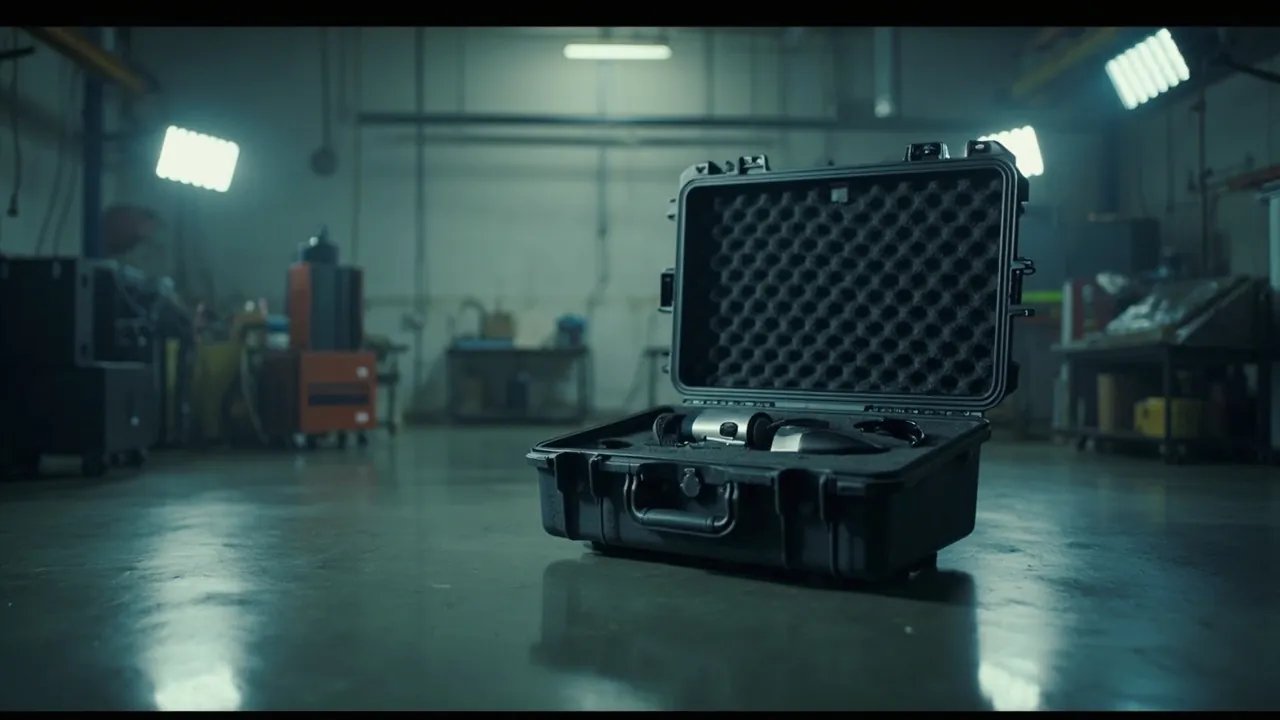
The first design red line for a subsea cable and laying equipment case is bend radius, the second is contamination control, and only the third is sealing and cushioning. This order runs opposite to most people's intuition, because the typical transport damage to subsea cable joints and accessories is not crushing but over-bending: fibre units develop macrobend loss and eventually break once the minimum bend radius is exceeded, insulation components develop microcracks after repeated flexing, and metallic sheaths and armour layers form stress concentrations at sharp bends. Selection should follow that same order. The insert must provide a support path for cables and joints that never falls below the minimum bend radius. Joint insulation components and metal parts need dedicated clean compartments with controlled humidity, underpinned by an IP rating defined against IEC 60529 and GB/T 4208. And the shell and hardware must be configured for corrosion resistance along the lines of ISO 9227 neutral salt spray testing. One boundary should also be stated: a transit case performs no electrical insulation function and does not replace type testing or routine factory testing of a joint. It delivers clean, dry, low-stress transfer of joints and accessories between the factory and the deck of a laying vessel. In understanding the design boundaries of subsea cable joints, the thinking behind extruded insulation power cable and accessory standards such as IEC 60840 and IEC 62067 is useful, along with the general awareness of subsea production systems conveyed by the ISO 13628 series. Note that a transit case is not covered by those cable standards; their value here is in judging which surfaces must never carry load. The sections below follow the sequence: object families, case types, bend radius, moisture and contamination, IP rating, shell corrosion, insert design, laying equipment, standards and testing, transport and vessel transfer, a six-step selection process, and acceptance and maintenance.
Procurement and logistics teams on subsea cable projects face a recurring tension. Joints and accessories are the highest unit value and most strictly verified items in the whole project, yet their packaging is often handled by the supplier as a matter of routine while project attention focuses on laying technique and testing. The result is that damage occurring during road and sea transport is only discovered at the pre-lay inspection, at which point the cost is no longer just the component but vessel standby and schedule slippage. The value of this article is in turning the transport requirements of subsea cable joints and accessories into clauses that can be written directly into a purchase specification, together with the physical reasoning behind them. JUNZHJIA supplies custom protective cases, EVA, EPE and PU insert and radiused support design, seal parts configured by component model, and OEM and ODM support with volume supply for subsea cable and marine cable customers, and can provide technical documentation covering shell material, hardware surface treatment and structural notes on request.
Table of Contents
- What a subsea cable and laying equipment case has to protect: from joints to accessories
- Three case types: joint cases, accessory cases and laying equipment cases
- Bend radius is the first red line: why bending is more dangerous than crushing
- Moisture and contamination control: the dual sensitivity of insulation and metal parts
- Choosing the IP rating: IP65, IP67, IP68 against IEC 60529 and GB/T 4208
- Shell and hardware corrosion control: ISO 9227 salt spray and galvanic corrosion
- Insert design: large diameter coiling, radiused supports and removable dividers
- Laying equipment cases: tension machinery, fairleads and burial tools
- Standards and testing: ISTA, GB/T 4857, ASTM D4169, MIL-STD-810H (not a military certification), UL94
- Transport, lifting and vessel transfer: classification-society awareness and cable laying practice
- A six-step selection process and project spare kit configuration
- Incoming acceptance, maintenance and asset life management
- Frequently Asked Questions
- Conclusion & Related Reading
What a subsea cable and laying equipment case has to protect: from joints to accessories
Subsea cable projects involve items with an enormous spread in form. There are flexible joint assemblies a few metres long and joint protection shells weighing tens of kilograms, fibre units that must not be bent and metal fasteners that must not rust. Sorting out the object family first is what reveals the hazard and the protection requirement.
| Object class | Typical items | Dominant failure mode | Key packaging requirement |
|---|---|---|---|
| --- | --- | --- | --- |
| Cable body and short lengths | Cable short lengths, spare tails, jumper assemblies | Exceeding minimum bend radius, sheath scratching, loose armour | Radiused support, large diameter coiling, sheath protection |
| Factory flexible joints | Flexible joint assemblies, injection moulded joints, moulded joints | Joint body crushing, insulation contamination, concentricity disturbance | Shaped support, clean compartment, no point loading |
| Repair joints and accessories | Repair joint kits, joint protection shells, seal kits | Seal face scoring, insulation moisture uptake, metal corrosion | Individual wrapping, moisture control, dedicated compartments |
| Terminations and connectors | Cable terminations, GIS termination accessories, connectors, earthing parts | Insulation surface contamination, end face impact, metal corrosion | Protective end caps, clean environment, moisture control |
| Fibre and signal units | Fibre units, sensing fibre, composite cable signal lines | Macrobend loss, fibre breakage, joint box moisture ingress | Large bend radius, crush prevention, moisture control |
| Laying machinery | Tensioners, track tensioner parts, fairleads, roller sets | Roller bearing brinelling, frame distortion, hydraulic corrosion | Vibration control, rust prevention, heavy load support |
| Burial and protection tools | Burial plough accessories, jetting tools, protection mats, weight blocks | Cutting edge damage, structural distortion, thread damage | Edge protection, interlayer separation |
| Test and inspection equipment | OTDR units, withstand test equipment, partial discharge detectors, diameter gauges | Moisture ingress, accuracy drift from vibration, screen cracking | Moisture control, vibration control, dedicated compartments |
Two key patterns emerge. First, the governing load type inside a subsea cable case is bending and squeezing, not dropping. An ordinary equipment case is primarily concerned with drop shock, whereas a subsea cable case is primarily concerned with whether cables and joints have been constrained into an unreasonable shape inside the case. A coil of insufficient diameter, a cable tie pressing on a joint, a support point pushing on an insulation component, each can cause irreversible damage. Second, the weight given to cleanliness is far higher than in an ordinary equipment case. Salt, oil, fingerprints and wear debris on joint insulation surfaces directly affect insulation performance and interfacial bonding quality, and site practice often assumes the item will be used straight out of the case, so packaging must guarantee cleanliness and dryness.
Three case types: joint cases, accessory cases and laying equipment cases
Subsea cable project case requirements fall into three categories whose design priorities differ completely. Mixing them produces either under-protection or wasted spend.
| Case type | Main contents | Design priority | Key metrics |
|---|---|---|---|
| --- | --- | --- | --- |
| Joint case | Flexible joints, repair joint kits, joint protection shells | Shaped support, cleanliness, moisture control, no point loading | Bend radius restraint, humidity control, floating end faces |
| Accessory case | Termination accessories, seal kits, fasteners, earthing parts, fibre units | Compartmentation, no mixing, moisture control, individual wrapping | Compartment precision, labelling, desiccant |
| Laying equipment case | Tensioner parts, fairleads, roller sets, burial tools | Heavy load support, vibration control, rust prevention, edge protection | Load capacity, lifting point strength, vibration resistance |
Joint cases are technically difficult because they must hold a shape. A flexible joint is a component with axial length that also needs to preserve concentricity and straightness, so the case must provide multiple support points along the axis, and those supports must not press on any seal face or insulation interface. In practice an independent cradle with a radiused groove suspends the joint body while soft restraint straps at each end limit movement without tightening.
Accessory cases are technically difficult because of compartmentation and labelling. A joint repair kit may contain dozens of parts that are similar in specification and appearance. Once mixed, they cannot be distinguished quickly on site, and fitting the wrong part can have serious consequences. Accessory cases should therefore be built on a one-kit-one-compartment principle, with part numbers and quantities engraved into the insert.
Laying equipment cases are technically difficult because of load bearing and rust prevention. Tensioners and roller sets are heavy, structurally complex and contain hydraulic and bearing components, so the case needs sufficient flexural stiffness and lifting point strength while hardware faces high corrosion demands in a marine environment. These cases usually require lifting or forklift handling, with a palletised or reinforced base.
Bend radius is the first red line: why bending is more dangerous than crushing
In subsea cable and fibre work, minimum bend radius is the most frequently cited and most frequently violated constraint. It matters because of three distinct failure mechanisms.
- Fibre units. Optical fibre is extremely bend sensitive. Once the bend radius falls below a critical value, the total internal reflection condition at the core-cladding interface breaks down and optical power leaks into the cladding and coating, producing macrobend loss. A smaller radius generates microcracks in the core and eventually a break. Such loss and breakage usually cannot be judged by appearance after transport and can only be found by OTDR testing, which is typically scheduled before laying, by which time several weeks have passed since packing.
- Insulation and sheath materials. Extruded insulation such as cross-linked polyethylene and sheath compounds become stiffer at low temperature. If forced to a small radius in that condition, microcracks form inside the material. Under the combined action of electrical stress and moisture, these microcracks develop into water trees, one of the classic long-term degradation mechanisms in extruded insulation cables.
- Metallic sheaths and armour. Lead and aluminium sheaths and steel wire or tape armour form stress concentrations when bent. Repeated bending loosens the armour and creases the sheath, and a crease is easily punctured by subsequent compression, becoming an ingress path for water.
| Object type (experience reference) | Common minimum bend radius | Notes |
|---|---|---|
| --- | --- | --- |
| Small diameter fibre and signal lines | Not less than 10 to 20 times outer diameter | Follow the supplier datasheet; static radius is usually larger than dynamic radius |
| Medium and low voltage power cable | Not less than 8 to 12 times outer diameter | Increase at low temperature |
| High voltage extruded insulation subsea cable | Not less than 15 to 25 times outer diameter | Larger values where armour and sheath structures are more complex |
| Factory flexible joint assemblies | As specified by the supplier, usually stricter than the cable of the same size | Bending prohibited in the joint body region |
One point deserves emphasis: the table above is an experience reference only, and actual values must come from the component supplier's datasheet, distinguishing dynamic bend radius, which may be applied during transport or laying, from static bend radius, which applies to long-term installed condition. Packaging design must ensure that the bend radius occurring anywhere during transport is no smaller than the dynamic limit. For arrangement methods inside the case, see the removable divider system.
Moisture and contamination control: the dual sensitivity of insulation and metal parts
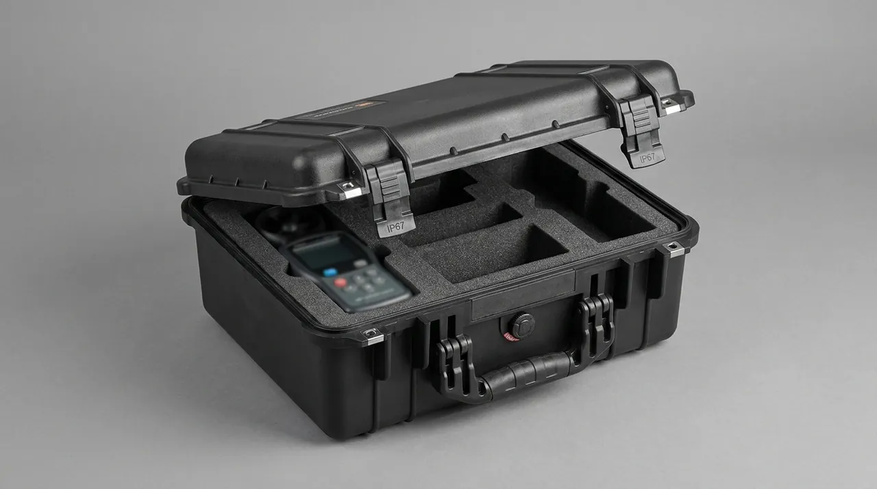
Why moisture control matters. After injection moulding or moulding at the factory, the insulation interfaces of a subsea cable joint have usually been vacuum treated or dried, leaving interfacial moisture content in a controlled state. If moisture is reabsorbed during transport and storage, the thin water film at the interface can initiate interfacial discharge and degradation under electrical stress, which is why so many joint failures trace back to moisture uptake during storage. Engineering practice includes a well-sealed case with an IP rating defined against IEC 60529 and GB/T 4208, a pressure equalisation valve to prevent differential pressure from damaging the seal, sufficient desiccant, and a humidity indicator card to record condition. For gasket material selection and ageing, see seal material selection and ageing criteria for protective cases. For how pressure equalisation works, see the function and selection of pressure equalisation valves.
Why contamination control matters. Cleanliness is as important as moisture control. Subsea cable joint installation has extremely strict requirements on interface cleanliness, and the common contamination sources are:
- Salt. Chlorides settling from quay and vessel environments form a conductive film once they absorb moisture on an insulation surface.
- Oil and fingerprints. Handling insulation surfaces bare-handed leaves grease and perspiration that affect interfacial bonding and insulation performance. Standard practice is powder-free gloves together with a cleaning solvent.
- Wear debris. Metal particles generated by rubbing between metal parts become local electric field concentration points if they enter an insulation interface.
- Packaging material emissions. Some low-cost foams and adhesives release plasticisers or acidic substances that contaminate insulation surfaces over long contact. Insert materials should therefore be selected for low emission and freedom from sulphur and chlorine.
How this lands in engineering practice. Joints and insulation components are placed into individual sealed or moisture barrier bags in a clean environment before being placed into the insert compartment. Metal parts and insulation parts are kept in separate compartments. A humidity indicator card goes into the case, and cleaning instructions travel with the case. These steps look laborious, but compared with rework discovered before laying, the cost difference is an order of magnitude.
Choosing the IP rating: IP65, IP67, IP68 against IEC 60529 and GB/T 4208
IEC 60529 and its national counterpart GB/T 4208 define the two-digit enclosure protection code. Selection logic for subsea cable cases matches offshore wind: set the rating by exposure duration and by whether the case is outdoors.
| IP rating | Dust | Water | Typical subsea cable project use scenario |
|---|---|---|---|
| --- | --- | --- | --- |
| IP65 | Dust protected | Protection against water jets | Factory workshop transfer, covered container transport, warehouse storage |
| IP66 | Dust protected | Protection against powerful water jets | Covered quay storage, short open-air loading |
| IP67 | Dust tight | Temporary immersion (typically 1 m for 30 min) | Open quay storage, wet loading, vessel transfer |
| IP68 | Dust tight | Continuous immersion (depth and duration by agreement) | Long-term open storage, laying vessel deck storage, risk of going overboard |
| IP69K | Dust tight | High-temperature high-pressure spray | Process areas requiring pressure washdown, generally not used for cable cases |
The usual configuration for subsea cable projects is: wherever open storage or vessel transfer occurs, a case with IP67 capability should be the baseline, moving to IP68 capability where a case sits long-term on a laying vessel deck or faces a risk of going overboard. Three points deserve attention. An IP rating only holds when the gasket is clean and intact, every latch is closed and the pressure equalisation device works. Joint cases are opened frequently for inspection, so the gasket wears faster and the inspection interval should be shortened. And heavier cases are harder to move around a vessel, so the rating choice must match actual lifting and handling capability. For verification methods and common misreadings, see sealing structure and testing points for IP67 protective cases. For the interaction of case mouth, hinges and latches, see integrated design of hinges, latches and seals.
Shell and hardware corrosion control: ISO 9227 salt spray and galvanic corrosion
Subsea cable cases are used in three environments, warehouse, quay and laying vessel deck, with the latter two imposing markedly higher corrosion demands.
- Engineering plastic shells, typically copolymer polypropylene. Non-rusting, light and non-conductive, and the most common choice for subsea cable accessory cases. Two points matter: a UV-stabilised compound is needed for long outdoor service, and large cases depend on ribs and case mouth geometry for reinforcement so that stacking does not deform the case mouth and release the gasket.
- Aluminium alloy shells. Good stiffness and load capacity, suitable for laying equipment parts and heavy tooling. Aluminium must be anodised or painted in salt-laden environments, and fasteners should be standardised to stainless steel to avoid a sound case with seized screws.
- Stainless steel shells. The best corrosion performance at the highest weight and cost, reserved for small high-value joint accessories.
- Galvanic corrosion in hardware. Hinges, latches, telescopic handles and castors are frequently dissimilar metals, creating galvanic couples in salt-laden environments. Standardising materials or adding insulating washers is recommended, with surface treatment and salt spray requirements stated explicitly in the purchase specification.
Corrosion capability is normally evaluated using ISO 9227 neutral salt spray testing. As a rule of thumb, plain carbon steel fasteners show visible red rust within tens of hours in a salt spray chamber, whereas suitably finished stainless hardware can remain free of red rust for several hundred hours. It is worth noting that salt spray results are not equivalent to a real marine environment: chloride deposition rates and wet-dry cycling frequency differ from actual offshore exposure, so results should serve as a comparative and acceptance criterion rather than a life prediction. When supplying subsea cable customers, JUNZHJIA can provide technical documentation covering shell material grade, UV-stabilised compound notes, hardware surface treatment and structural notes as required.
| Corrosion protection | Typical salt spray performance (experience reference) | Suitable locations | Cautions |
|---|---|---|---|
| --- | --- | --- | --- |
| Stainless steel (304 / 316 series) | Several hundred hours without red rust | Hinges, latches, telescopic handles, fasteners | 316 series better suited to high-chloride coastal service |
| Anodising (aluminium) | Medium to high depending on film thickness and sealing | Aluminium shells, frame parts | Film damage becomes a corrosion initiation site |
| Powder coating | Depends on film thickness and adhesion | Exposed structural parts, equipment frames | Edge coverage must be controlled in the process |
| Hot dip galvanising | Hundreds of hours depending on coating thickness | Structural parts, burial tools, weight blocks | Edges and cut faces require touch-up |
| Conversion coating for fasteners | Hundreds of hours with no hydrogen embrittlement risk | High-strength fasteners | Tied to friction coefficient and torque requirements |
Insert design: large diameter coiling, radiused supports and removable dividers
The insert is where engineering capability shows most clearly in a subsea cable case. It has four problems to solve: bend radius control, avoidance of point loading, maintenance of cleanliness, and ease of inventory.
Supporting straight sections and short lengths. Where space allows, cable short lengths and jumper assemblies are best carried straight or in a large arc rather than in a small coil. The practice is to place cradle supports with radiused grooves along the length at intervals determined by cable stiffness, generally 300 to 600 mm. Cradle edges must be radiused and covered with soft material so the sheath is not creased under pressure.
What to do when coiling is unavoidable. Where a cable is too long to carry straight, use a large diameter spool or radiused baffle so the coil diameter satisfies the minimum bend radius. Separate coil layers with soft interleaving to prevent layer-to-layer compression, and secure the entry and exit ends at dedicated positions so the tail cannot bend out of the coil at a sharp angle. Cable ties deserve special warning as a hidden hazard. Pulling a cable into a small loop with a tie creates a local bend radius far below the design value at the tightening point. Wide hook-and-loop straps or soft restraint straps are preferable, with fixing points placed on straight sections where bend radius is generous.
Shaped support for joint bodies. A joint body usually needs to preserve concentricity and straightness, so packaging should support it at both ends with the middle suspended, or at multiple equidistant points, with support points kept clear of seal faces and insulation interfaces. No point load should act on the middle of a joint body, and the joint body should never carry its own weight through a hard contact.
Removable dividers and inventory. Parts inside an accessory case are similar in specification, so removable divider strips or individual small boxes are recommended to isolate each accessory kit, with part numbers and quantities engraved into the insert and a packing list pocket to allow contents to be confirmed at a glance. For implementation options, see the removable divider system.
| Insert material | Characteristics | Suitable subsea cable items | Cautions |
|---|---|---|---|
| --- | --- | --- | --- |
| EVA (medium to high density) | Precisely machined, dimensionally stable, good rebound | Joint accessories, seal kits, connectors, small tools | Select low-emission compounds to avoid insulation contamination |
| EPE (low density) | Light, long cushioning stroke, low cost | Protection mats, weight blocks, large light items | Rebound decays after repeated compression |
| PU foam | Firmness tunable by density, strong energy absorption | Tensioner parts, roller sets, heavy items | Relatively higher moisture uptake, needs sealing or desiccant |
| Cross-linked PE foam | Tear resistant, good weather resistance | Returnable cases with frequent opening | Slightly harder to machine |
| Soft facing materials (felt, soft foam) | One-directional softness, anti-scratch | Cradle surfaces in direct contact with sheaths and insulation | Inspect periodically for detachment or contamination |
For a side-by-side comparison of foam and insert materials, see the case foam material comparison and the custom foam insert design guide.
Laying equipment cases: tension machinery, fairleads and burial tools
Laying equipment cases follow a very different design logic from joint and accessory cases. They are closer to heavy duty tool cases.
Tension machinery and roller sets. These components contain bearings, hydraulic parts and precision mating surfaces. The main transport risks are false brinelling of bearings from sustained vibration, kinked hydraulic hoses and frame distortion. Protection points include axial restraint to prevent shuffling, medium-hardness foam support around the circumference without over-compression, hydraulic hoses coiled at no less than the minimum bend radius with port plugs fitted, and multi-point frame support to avoid long unsupported spans.
Fairleads and guide components. The curved surface of a fairlead is a functional surface. Once damaged it changes the load distribution as cable passes through and can even score the sheath. Packaging should provide relief and soft covering for curved surfaces, with no direct contact against metal items.
Burial and protection tools. Burial plough accessories, jetting tools, protection mats and weight blocks are usually heavy and carry cutting edges or sharp corners. Cutting edges must have protective caps, interlayers must separate stacked items, and threads must carry protective caps. Load bearing for these items should pass directly into the reinforced case base rather than being transferred through layers of foam.
Test and inspection equipment. OTDR units, withstand test equipment, partial discharge detectors and diameter gauges are precision instruments requiring moisture control, vibration control and end face protection. Screens and optical windows need dedicated relief, and antistatic inserts may be required. For the compartment logic of instrument-type components, see the instrument case selection guide. For shock and vibration control practice, see shock and vibration resistant case design.
A field observation worth noting: the most common problem with a laying equipment case is not that things will not fit but that they cannot be packed back afterwards. Once a roller set is removed, hoses, shims and bolts scatter, and the original positions cannot be found on reassembly. The insert should therefore be designed so that disassembly and reassembly are reversible, with a fixed and clearly labelled position for every removable part.
Standards and testing: ISTA, GB/T 4857, ASTM D4169, MIL-STD-810H (not a military certification), UL94
Packaging requirements for subsea cable projects usually appear in the technical specification. The table below clarifies where each common standard applies. Note that MIL-STD-810H is used here purely as a reference for environmental test methodology and is not a military certification, and that IEC 60840 and IEC 62067 are product standards for extruded insulation power cables and their accessories, useful for understanding joint design and test boundaries, with transit cases outside their scope.
| Standard | Content | Application in subsea cable cases |
|---|---|---|
| --- | --- | --- |
| IEC 60529 / GB/T 4208 | Enclosure protection ratings (IP code) | Defines dust and water ratings and test methods |
| ISO 9227 | Corrosion tests in artificial atmospheres: salt spray tests | Salt spray evaluation of shell and hardware |
| ISTA series | Performance testing of transport packages | Full case drop, vibration and compression verification |
| GB/T 4857 series | Basic tests for transport packages | Common test and reporting basis for domestic projects |
| ASTM D4169 | Performance testing of shipping containers and systems | Distribution cycle simulation for international customers |
| MIL-STD-810H | Environmental test methods (vibration, shock, temperature, humidity, salt fog and more) | Reference for test profile design (not a military certification) |
| UL94 | Flammability testing of plastics | Flame retardance class for foams and plastics where required |
| IEC 60840 / IEC 62067 | Extruded insulation power cables and their accessories | Understanding joint design and test boundaries, transit cases not covered |
| ISO 13628 series | Design and operation of subsea production systems | General reference for the watertight design boundary of subsea components |
The recommended combination is: type verification of the IP rating to IEC 60529, salt spray testing of the shell and hardware to ISO 9227, drop and vibration testing of the fully packed case to ISTA or GB/T 4857, additional temperature-humidity cycling verification for joint cases to confirm long-term moisture resistance, and UL94 classification of foam where flame retardance is required. For procedures, see the ISTA transport testing procedure, GB/T 4857 transport packaging testing and ASTM D4169 distribution cycle simulation. The general logic of environmental test profiles is covered in interpreting MIL-STD-810H environmental test compliance. For joint cases held in storage long-term, see case design for extreme temperature environments.
Transport, lifting and vessel transfer: classification-society awareness and cable laying practice
The real journey of a subsea cable case typically runs: factory, road transport, port warehouse, sea freight by container or breakbulk, port of destination, quay, laying vessel, deck staging, laying operation. Each leg has a different dominant hazard.
- Road transport. The dominant hazards are road vibration and longitudinal shock from hard braking. Heavy laying equipment cases must be secured and heavy internal items restrained axially; joint cases should not share a pallet with other heavy cargo.
- Sea freight. The dominant hazards are sustained high humidity, salt spray and internal temperature cycling. Place sufficient desiccant and a humidity indicator card inside; avoid direct contact with the container wall where condensation droplets can fall on the case; and observe the stacking limit strictly. Joint cases benefit from added moisture and do-not-invert markings with a record of loading condition.
- Quay and vessel transfer. The dominant hazards are rough handling and occasional drops. Cases should carry clear lifting, centre-of-gravity and orientation markings; heavy cases should have lifting points or a palletised base; and sling angle and load should match lifting point strength. Transfer space on a laying vessel is often tight, so external dimensions should be as regular as possible to prevent protrusions striking structures in passageways.
- Deck staging. The dominant hazards are salt spray, ultraviolet radiation, wave splash and hull vibration. Keep cases off the deck and secured, shorten the humidity inspection interval for cases in long storage, and open cases in a relatively clean and sheltered area where possible.
Classification societies including DNV and ABS publish extensive rules and recommended practice on offshore transport, lifting and sea fastening, and project documents commonly cite their general principles to specify securing, stacking and lifting. It should be clear that a transit case is not itself a classification society certified item, but citing those general principles helps packaging documentation pass owner and general contractor review. For how this lands in practice and how suppliers should be screened, see how to choose a protective case OEM factory. For handling format choices in confined spaces, see portable transport case types compared.
A six-step selection process and project spare kit configuration
- Build the object list with critical constraints. Record name, envelope including protruding joint sections, net mass, minimum dynamic and static bend radius, sensitive face locations such as seal faces, insulation interfaces, end faces and optical windows, whether the item is static sensitive, and whether it carries a calibrated state. The output should be a table, not prose.
- Define the transport route and exposure. Establish the road and sea split, whether open storage occurs, whether the case goes on deck, storage duration and whether it passes through high salt spray sea areas. Set the IP target, usually from IP67 upward with IP68 capability for long-term deck storage, and decide whether a pressure equalisation valve is mandatory.
- Define the bend radius and support scheme. Convert the minimum bend radius into concrete hardware dimensions: spool core diameter, radiused cradle radius, cradle spacing and interlayer thickness. Every surface in direct contact with cable must be radiused and covered with soft material.
- Define the insert concept and cleanliness requirements. Separate compartments by object type, with insulation parts, metal parts, tools and instruments in their own compartments. Select low-emission insert materials free of sulphur and chlorine. Build removable compartments for each accessory kit with engraved part numbers.
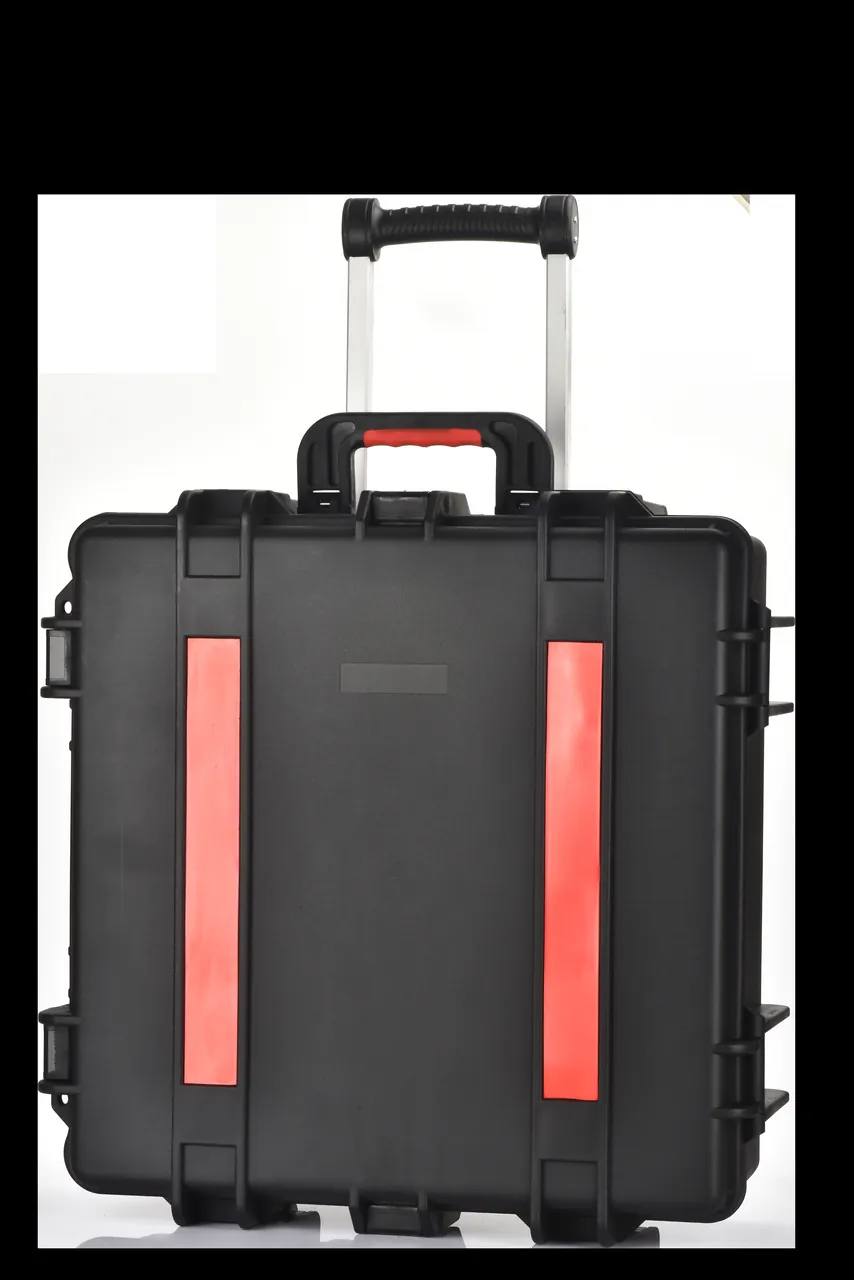
- Define case type, volume and handling method. Choose hand-carry, wheeled trolley or vehicle-stacked format by unit mass, verify compressive capacity against the stacking requirement, decide lifting point layout, and provide positions for desiccant and a humidity indicator card in joint cases, including whether additional moisture barrier bags are needed.
- Define acceptance and documentation. Agree incoming inspection items covering appearance, dimensions, gasket condition, latch effort, insert and bend radius conformity, compartment and label accuracy and humidity indicator status, along with sampling level and acceptance rules, and require shell material and UV notes, hardware surface treatment notes and optional salt spray and transport test reports. For sampling scheme design see custom case acceptance and AQL sampling.
Incoming acceptance, maintenance and asset life management
Incoming acceptance checklist
- Shell free of cracks, distortion and dents; no chalking or coating loss on surfaces intended for long outdoor service.
- Gasket complete, not twisted, free of trapped foreign matter; seal groove clean and free of particles.
- Latches fully engaged with consistent effort; hinges free of play, corrosion and noise.
- Pressure equalisation membrane clean with the protective cap in place.
- Insert radiused cradles and spool radii conform to the minimum bend radius requirement; soft facings intact and not detached.
- Compartments and labels match the packing list; accessory quantities complete.
- Desiccant and humidity indicator card present in the agreed quantity, with the indicator in the expected state.
- Accompanying documents, including material notes, surface treatment notes, test reports and cleaning instructions, complete.
Routine maintenance recommendations
- Clean the seal groove and case mouth after each use with mild detergent and a soft cloth; never use solvent-based or strongly alkaline cleaners. See correct cleaning and care for protective cases.
- Inspect the gasket every 6 to 12 months, shortening to 3 to 6 months for joint cases opened frequently; replace immediately on hardening, cracking or permanent flattening.
- During long storage, leave latches slightly open or ventilate periodically so the gasket is not permanently compressed, and replace desiccant on schedule with indicator card readings used to judge moisture exposure.
- Verify accessory quantities and part numbers after each opening to prevent parts being left on site, and maintain an opening and inventory record.
- Check insert soft facings and radiused cradles for deformation, detachment or contamination and replace them promptly, since they directly determine whether bend radius requirements are met.
- Maintain a case number to component to transport record log so high-value joint accessories remain fully traceable. On overall condition assessment and replacement timing, see protective case service life and replacement criteria.
Frequently Asked Questions
Q: Why does a subsea cable joint case put bend radius first rather than vibration resistance?
A: Because the typical damage mechanisms are different from those of ordinary equipment. An ordinary equipment case fears drop shock, whereas the most common damage inside a subsea cable case comes from a shape being forced into an unacceptable form. Fibre units develop macrobend loss once the bend radius falls below a critical value because the total internal reflection condition breaks down, and a smaller radius causes core microcracks and eventual breakage. None of this is visible after packing and can only be found by OTDR testing. Extruded insulation and sheath materials become stiffer at low temperature, and forced bending generates internal microcracks that develop into water trees under the combined action of electrical stress and moisture, one of the classic degradation mechanisms of extruded insulation cable. Metallic sheaths and armour form stress concentrations at bends, and creases are easily punctured by later compression to become water ingress paths. The first packaging priority is therefore ensuring that bend radius along the entire path never falls below the dynamic limit, with cushioning and sealing coming after.
Q: How is minimum bend radius implemented in packaging, and is stating a number enough?
A: A number alone is not enough. The minimum bend radius from the supplier is a constraint, and packaging design must convert it into concrete hardware dimensions. The first step is distinguishing dynamic from static bend radius, controlling any bending that may occur in transit to the dynamic limit, which is usually larger than the static radius. The second step is converting the radius into structure: the spool core diameter should be at least twice the radius, radiused cradle concave surfaces should be no smaller than the limit, and cradle spacing should follow cable stiffness and generally not exceed 600 mm. The third step is eliminating local small radii at tie points, tail exits and pass-through apertures, where local radius is often far below the design value. The fourth step is interlayering, using soft separators between coil layers so the weight above does not flatten the layer below. Finally, critical radii should be measured during acceptance rather than simply checked on the drawing.
Q: Why is cleanliness so critical for joint insulation components?
A: Because the performance of an insulation interface is extremely sensitive to surface condition. After injection moulding or moulding at the factory, joint insulation interfaces have usually been vacuum treated or dried, leaving interfacial moisture content and cleanliness in a controlled state. If salt, oil, fingerprints or metal wear debris contaminate the interface during transport and storage, these contaminants create local electric field concentration points or conductive channels that initiate interfacial discharge and degradation under the combined action of electrical stress and moisture. Salt is especially insidious because chloride deposits absorb moisture and form a conductive film that is barely visible. Engineering practice therefore places joints and insulation parts into individual sealed or moisture barrier bags in a clean environment before they go into the case, keeps metal parts and insulation parts in separate compartments, selects low-emission insert materials free of sulphur and chlorine to prevent plasticiser or acidic migration, includes a humidity indicator card, and requires powder-free gloves on site.
Q: Why do subsea cable accessory cases need removable dividers and engraved numbering?
A: Because a joint repair kit or termination accessory set often contains dozens of parts with similar specifications and appearance. Once mixed, they cannot be distinguished quickly on site, and fitting the wrong part can be serious. Removable divider strips or individual small boxes isolate each accessory kit with a fixed position for both withdrawal and return, avoiding the situation where parts cannot be packed back. Engraving part numbers and quantities into the insert, together with a packing list pocket, allows contents to be confirmed in a few tens of seconds. Two further benefits follow. Returns and quality investigations can locate a specific batch quickly, and when a project needs to add or remove accessory types, only the divider strips need adjusting rather than re-machining a whole insert. For offshore work this saves the most expensive resource of all, waiting time inside an operating window. Labelling should also survive the working environment, which in practice means engraving or a durable printed label bonded to the insert rather than a paper tag that will be lost the first time the case is opened at sea.
Q: Can laying equipment and joint accessories share the same case type?
A: It is not advisable, because the design logics differ substantially. A joint accessory case is about cleanliness, moisture control, bend radius control and fine compartmentation. It is usually a medium or light case emphasising sealing performance and insert precision. A laying equipment case carries heavy tooling such as tensioner parts, roller sets and burial tools, where the priorities are load capacity, lifting point strength, vibration control and rust prevention. The shell needs high flexural stiffness and loads must pass through rigid support columns directly into the reinforced case base rather than through layers of foam. Placing heavy tooling into a case designed for joints creates two problems: insufficient shell stiffness, so the case mouth deforms under stacking or a drop and the seal loses compression, and inadequate rigid restraint of heavy items inside, so sustained vibration produces bearing indentation and frame distortion. The sound approach is to configure different case series by purpose while standardising case numbering and labelling so asset management remains consistent.
Q: What IP rating should a subsea cable case carry?
A: Set it by exposure, with IP67 capability as the usual marine baseline. If the case stays in a covered container or roofed warehouse throughout, IP65 capability is sufficient. Wherever open storage, wet loading or vessel transfer occurs, IP67 capability should be the baseline, because temporary immersion and powerful spray genuinely occur in those situations. Only where a case will sit long-term on a laying vessel deck or in an open yard, or where there is a risk of going overboard, is IP68 capability worth considering, at the cost of heavier latches, a thicker sealing structure and less convenient opening, which matters because transfer space on a laying vessel is usually tight. Two supporting requirements are not optional. Joint cases are opened frequently for inspection, so gaskets wear faster and the inspection interval should be shortened. And shells used long-term outdoors must use a UV-stabilised compound, otherwise chalking and embrittlement deform the sealing surfaces.
Q: How should desiccant and humidity indicator cards be used to be effective?
A: The key is treating them as recordable, traceable technical instruments rather than symbolic accessories. Practical steps include calculating desiccant quantity from case volume and transport duration rather than adding a few sachets at random; recording the desiccant loading date and the initial state of the humidity indicator card at packing; reading the indicator card before removing components on opening, so that if the indicated threshold is exceeded the component undergoes insulation resistance testing or drying before use; replacing desiccant on schedule because it has a saturation limit and a single loading cannot last indefinitely through a long transit or long storage; and placing a small indicator card inside individual moisture barrier bags in joint cases so that a whole-case moisture problem can be distinguished from a single failed package. Once these records are part of the transport log, the vague question of whether moisture exposure occurred becomes documented data. It is also worth standardising the threshold at which action is taken, so that the decision to dry or retest a joint does not depend on who happens to open the case.
Q: What do DNV or ABS rules require of a subsea cable transport case?
A: First, a clarification: a transit case is normally not a classification society certified item and has no corresponding certificate. The rules and recommended practice published by DNV, ABS and others address offshore transport, lifting operations, sea fastening and stacking. In project practice they are cited in the transport plan to specify sling selection, lifting point strength, securing method, stacking height and storage conditions. For a case supplier, the task is to provide the information these requirements demand: designed capacity of lifting points, permitted stacking height, centre-of-gravity position, acceptable lifting methods, external dimensions and total mass. Writing these data into technical documentation helps the packaging plan pass owner and general contractor review and prevents site teams from adopting inappropriate lifting methods because information was missing. Offshore lifting space is usually constrained, and making lifting point positions and centre-of-gravity markings clear in advance delivers a direct improvement in site efficiency. Where a case is one of a batch, a single data sheet covering the series is usually sufficient, provided it identifies the specific model that will be delivered.
Q: What maintenance points matter when joint cases are stored long-term on a laying vessel?
A: The vessel environment combines salt spray, humidity, ultraviolet, wave splash and hull vibration, so maintenance priorities differ from a land-based warehouse. Gasket inspection should be increased to every 3 to 6 months, with immediate replacement on hardening, cracking, permanent flattening or surface tackiness. Hinges, latches, telescopic handles and castors should be checked quarterly for corrosion and smooth operation. Cases should not be exposed to prolonged direct sunlight or placed directly on the deck where the base sits in pooled water, and securing should be re-checked periodically to prevent sliding in heavy weather. Joint cases are opened repeatedly for inspection and withdrawal, so latches should be closed again promptly to prevent internal humidity accumulation, and opening work should be carried out in a sheltered and relatively clean area so salt spray does not enter directly. Desiccant and moisture barrier bags should be replaced on schedule with indicator card status logged, and a quarterly record is advisable during long storage. Insert soft facings and radiused cradles should be inspected periodically because they directly determine whether bend radius requirements are met.
Conclusion & Related Reading
The design logic of a subsea cable and laying equipment case reduces to three statements: bend radius is a hard constraint, cleanliness is a hard requirement, and corrosion control is a hard investment. Bend radius is a hard constraint because it cannot be substituted by thicker foam or a stronger shell; it must be implemented through concrete structure such as spool diameter, radiused cradle radius and cradle spacing. Cleanliness is a hard requirement because once a joint insulation interface is contaminated with salt, oil or wear debris, the effect only emerges during operation, so insert materials must be low emission, compartments must be separated, and opening records must be kept. Corrosion control is a hard investment because quay and laying vessel deck environments demand that shell and hardware solve the problem at material level rather than relying on later maintenance. In execution that means setting the IP rating against IEC 60529 and GB/T 4208, defining salt spray and corrosion requirements against ISO 9227, selecting transport tests against ISTA, GB/T 4857 and ASTM D4169 with MIL-STD-810H used only as an environmental test method reference and not as a military certification, and designing inserts and supports around the minimum bend radius. JUNZHJIA supplies custom protective cases, EVA, EPE and PU insert and radiused support design, seal parts configured by component model, and OEM and ODM support with volume supply for subsea cable and marine cable customers, and can provide technical documentation covering shell material, UV-stabilised compound and hardware surface treatment as projects require.
Related Reading