

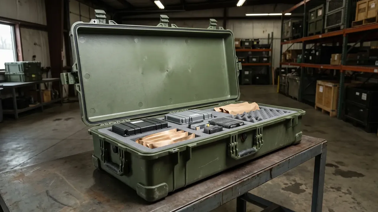
Quick answer: Industrial robotic arm parts shockproof box sizing starts at a 40 g fragility limit, held by a 30 mm EVA pad at 45 kg/m³ on an 0.8 m drop.
Table of contents
- Fragility rating of the industrial robotic arm parts shockproof box
- Cushion thickness versus impact acceleration
- Resonance band avoidance and sweep testing
- Parts colliding inside one case
- Cushion recovery and service life after unpacking
- FAQ
1. Fragility rating of the industrial robotic arm parts shockproof box
The costliest item in a robot arm is not the casting but the reducer inside. A harmonic flexspline runs at a wall near 0.3 mm, and acceleration beyond its limit leaves no mark, only lost repeatability later. An industrial robotic arm parts shockproof box holds every transit peak below that limit.
Fragility is the highest acceleration a part survives without losing function. ASTM D3332 lifts the shock level until the part fails, then steps back once as design value. Precision assemblies sit between 20 g and 60 g: a harmonic reducer at 40 g, a bare casting above 60 g, an encoder servo lower.
| Fragility band | Typical parts | Cushion direction |
|---|---|---|
| 40 g and below | Encoders, flexsplines | Thicker, softer foam |
| Around 40 g | Harmonic and RV reducers | 30 mm at 45 kg/m³, 0.8 m check |
| 60 g and above | Castings, flanges | Thinner pad, limit blocks |
Borrowing a whole machine's fragility for one part is the usual error. A lone part rests on two bosses, so the same 40 g becomes a local stress one band higher at the teeth. The 550×400×255 mm cavity of the industrial robotic arm parts shockproof box came from the largest part plus 25 mm of foam a side.
2. Cushion thickness versus impact acceleration
Thickness follows the drop, not the 5.0 mm wall. A 0.8 m fall reaches 3.96 m/s, and stopping it inside 35 g needs about 23 mm of travel. A 30 mm pad compressed to 23 mm works at 77% strain; the last 7 mm keeps the peak from breaking through.
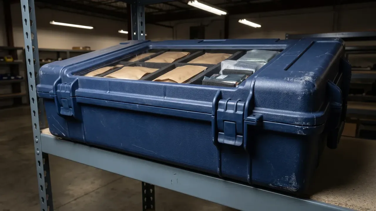
Density and thickness are set together. 45 kg/m³ sits at the low edge of the 38–100 kg/m³ range, so the curve stays flat for a part near 3 kg. At 80 kg/m³ the same pad stiffens after 18 mm. The 12.6 kg case shares load over 4 points, about 31 N each.
| Cushion thickness | Usable stroke | Peak at an 0.8 m drop |
|---|---|---|
| 20 mm | 15 mm | About 53 g, over limit |
| 30 mm | 23 mm | About 35 g, 5 g spare |
| 40 mm | 30 mm | About 27 g, less height |
Read backwards: fragility, stroke, thickness. The industrial robotic arm parts shockproof box fixes cavity height at 255 mm, so 30 mm to 40 mm of foam costs 20 mm of part height while the envelope stays 600×450×300 mm.
3. Resonance band avoidance and sweep testing
A drop happens once; vibration runs for hours. GB/T 4857.10 sweeps a packed case from 3 Hz to 100 Hz and plots response over input acceleration; above a ratio of 2 the package is at main resonance. This industrial robotic arm parts shockproof box is swept 5–200 Hz, 15 min a run.
Amplification is the hazard. Road energy sits at low frequency, and a system landing at 45 Hz turns 0.5 g at the road into 3 g inside the cavity. Soften the pad or raise static stress.
| Resonance band | Band character | Handling |
|---|---|---|
| Below 35 Hz | Overlaps suspension | Raise stress, lift frequency |
| Near 45 Hz | Lid first bending | Change pad or add a mid-divider |
| Above 55 Hz | Energy already low | Keep structure |
Put a 40 g harmonic reducer on a 30 mm pad with the resonance band at 45 Hz, and one sweep exposes it.
4. Parts colliding inside one case
One part per case is simple; shipments often carry three. With 3 parts inside, spacing cannot drop below 25 mm. That travel is reserved for lateral shock: a struck side wall compresses and springs back, neighbours close in, and the first contact is a flange face.
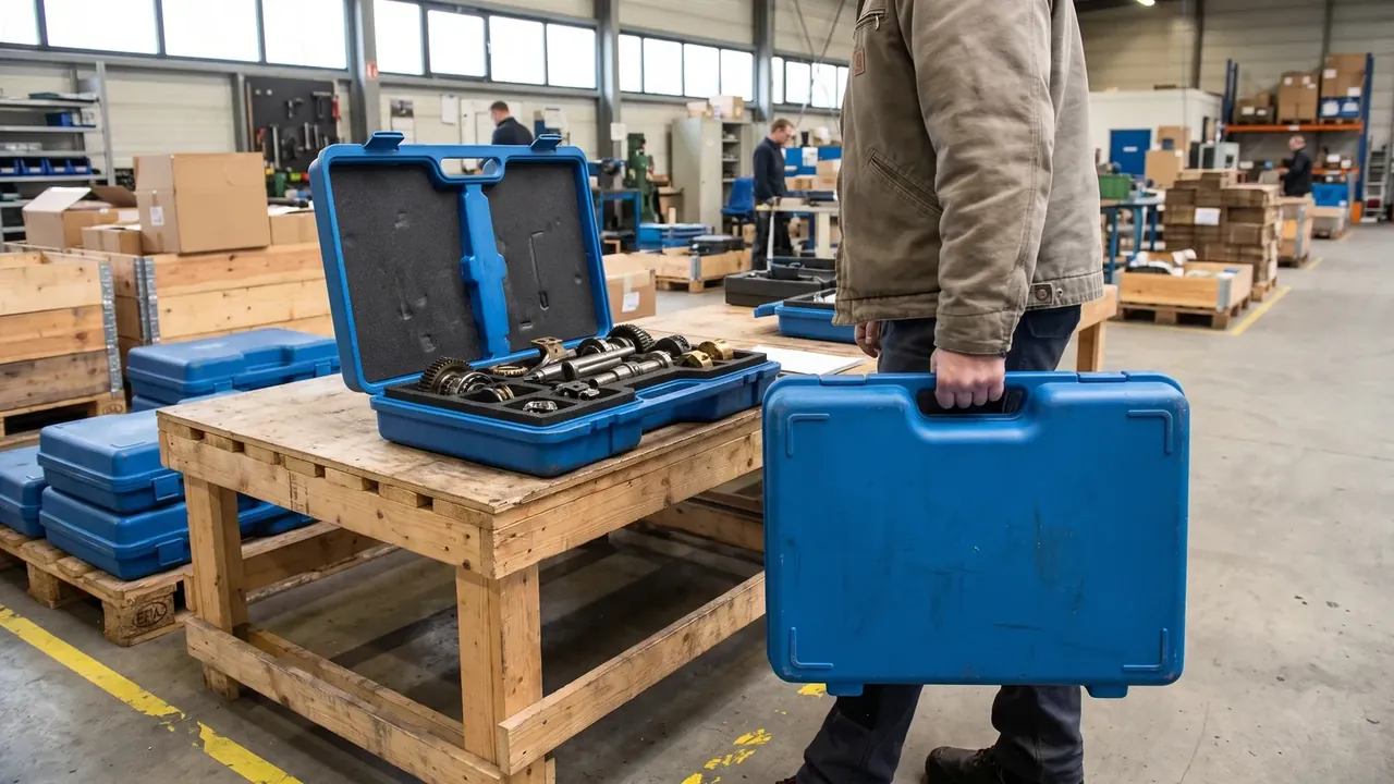
Limit points matter more than pad thickness. Four per part, on the stiffest features: two diagonal flange corners and both ends of a housing rib. Blocks carry a 45° chamfer, so load pushes toward the cavity floor. Dividers 25 mm wide split the industrial robotic arm parts shockproof box into three bays, 10 mm above the centre of gravity.
5. Cushion recovery and service life after unpacking
EVA does not recover forever. Under ASTM D3574 compression set, a 45 kg/m³ grade at 70 °C and 25% deflection for 22 h should lose under 5% of thickness, leaving 28.5 mm on a 30 mm pad.
At a 3 mm gap the part slides sideways, travel is spent before impact, and the peak climbs. Pads go back flat with corners pressed, cavity depth measured once. After 50 cycles, under 28 mm means a new pad.
Storage matters too: foam left compressed under stacked cases takes a set sooner. At −20 °C EVA stiffens and recovers slowly, so a case moved from cold store to warm shop is packed while the pad is thin.
Conclusion
Design order for an industrial robotic arm parts shockproof box runs fragility, stroke, thickness, frequency, then the shell. A 40 g limit means holding an 0.8 m drop to 35 g, which a 30 mm pad at 45 kg/m³ does by compressing to 23 mm. Three parts share the cavity at 25 mm spacing on 4 limit points, the 5–200 Hz sweep locates the 45 Hz band, and 4 latches rated at 420 N keep IP65 from −20 °C to +60 °C under 3-high stacking.
Related Reading
- Volume and Spacing for Multiple Parts
- Cases versus Wooden Frames for Precision Parts
- Shock Lining Reference for Optics
Related Products
- 8 Series — Gun Cases; Military Equipment Cases; Camera Equipment Cases; Drone Cases; Watch Cases; Knife Cases; First Aid Cases; Electronics Equipment Cases
- WL8-2812 PP Gun Case — model WL8-2812
- All protective cases and toolboxes: 7 series, 158 models