

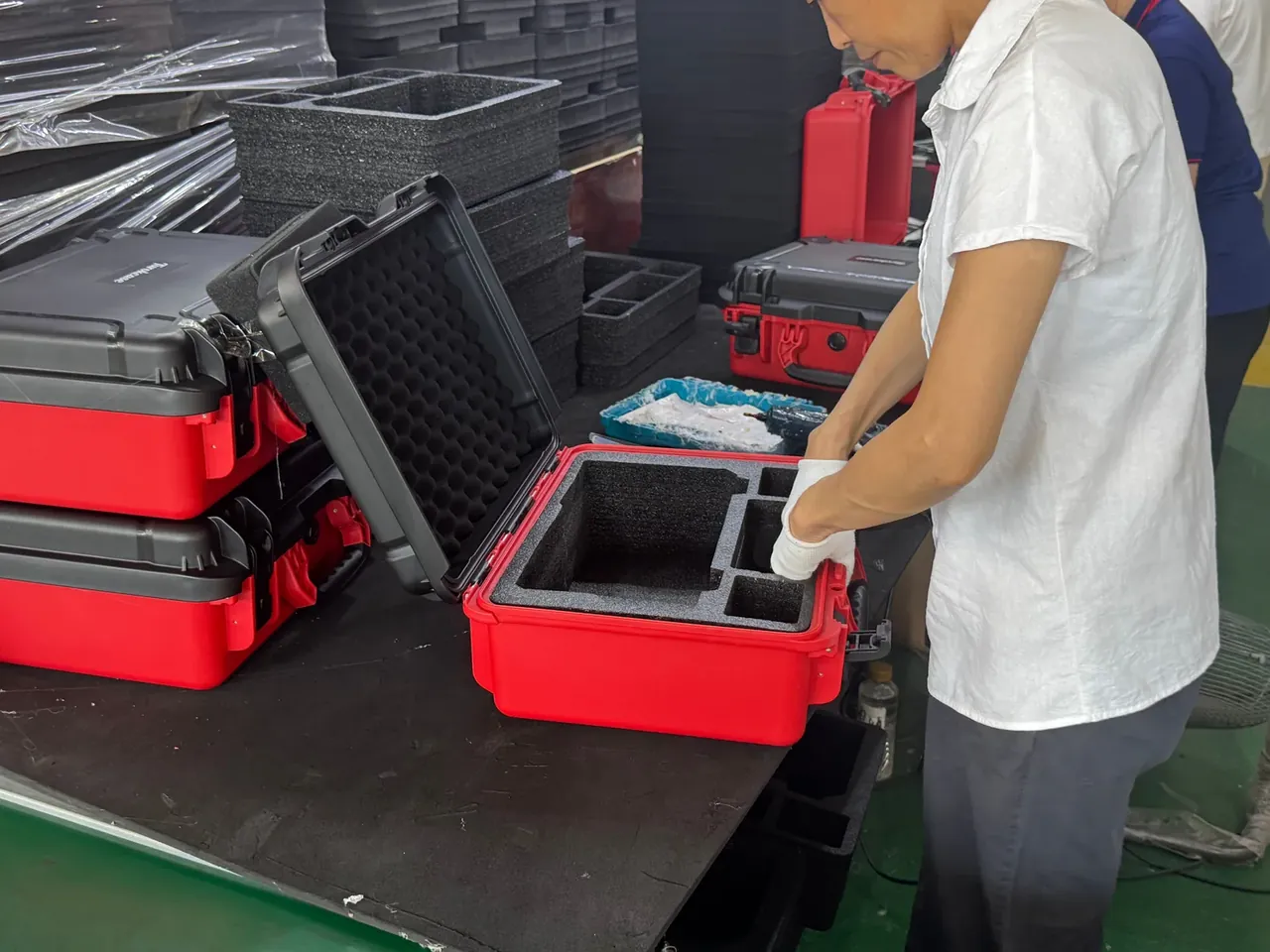
Quick answer: Growing instrument case depth from 300 to 400 mm lifts the tip angle from 39.8° to 48.0°, yet a 50 mm forward shift of the load erases all of it. Centre of gravity height, not depth, decides stability.
Table of contents
- Deeper is not steadier
- Measuring the centre of gravity height
- Fore and aft offset and ballast
- Handle position against the base
- Vibration and three impacts along the depth
- FAQ
1. Deeper is not steadier
Raising instrument case depth from 300 to 400 mm feels like a stability upgrade, because the lever arm from the tipping edge grows. The geometry agrees: 8 more degrees. But equipment is not welded to the base, so a deeper box invites the load forward by about 50 mm, and half the gain disappears.
One criterion settles it: the horizontal distance from the load centre to the front bottom edge, divided by the centre height, gives the tip angle by arctangent. Depth, width and ballast all feed into that ratio, so no feel is needed.
| Depth | Centre height | Load position | Tip angle |
|---|---|---|---|
| 300 mm | 180 mm | centred | 39.8° |
| 400 mm | 180 mm | centred | 48.0° |
| 400 mm | 180 mm | 50 mm forward | 39.8° |
| 300 mm | 240 mm | centred | 32.0° |
| 400 mm | 240 mm | 50 mm forward | 32.0° |
The third row is the point: 100 mm of extra depth buys 8°, and 50 mm of forward shift spends it. In the last row a 400 mm case with a 240 mm centre behaves exactly like a 300 mm case. Depth is a dimension; centre height is the variable.
2. Measuring the centre of gravity height
Slinging is quickest. Move two straps along the sides until the case hangs level, and the crossing point of the strap lines marks the centre; its height above the base is the centre height, repeatable within 5 mm. An 18 kg instrument case usually sits 230 to 260 mm up, roughly 40 mm above the geometric centre.
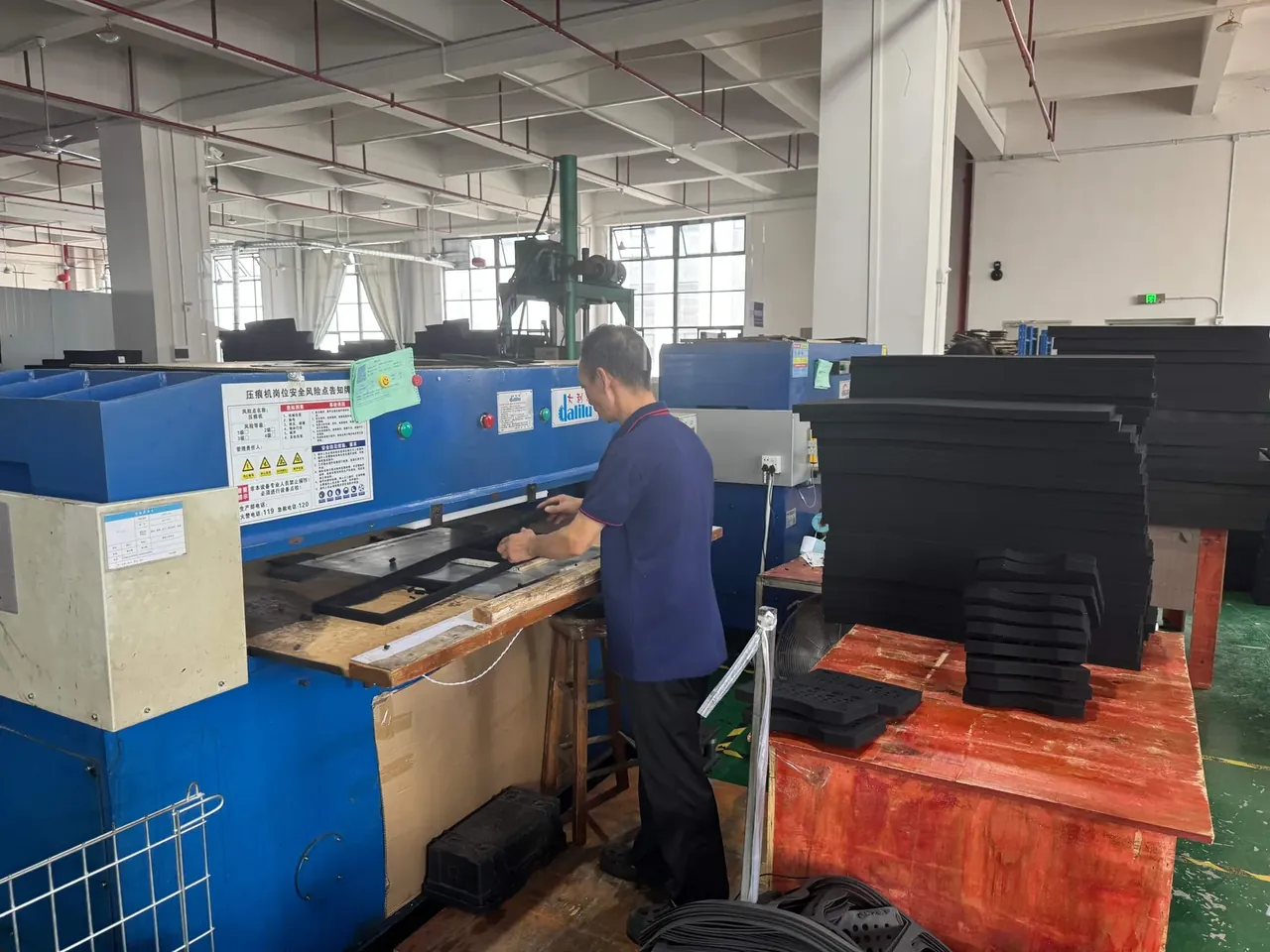
The three-point method belongs in an inspection sheet. Two platform scales under the front corners and one under the rear corner give three readings, and moment balance returns the fore-aft position and the height in one pass, repeatable to 2 mm.
Centre height is a sensitive input. At 300 mm depth a 240 mm centre gives 32.0°, and 260 mm drops to 30.0°, or 2° per 20 mm. Two degrees reads as noise in a lab and as a fallen case on a loading dock.
3. Fore and aft offset and ballast
Fore and aft offset is the quiet load along the depth direction. Shift the equipment 50 mm forward and the front feet carry 11.3 kg instead of 9.0 kg, while the rear feet drop to 6.7 kg, so the ratio moves from 1:1 to 1.7:1 and pad compression differs by 0.6 mm.
Where the ballast sits decides whether it helps. With the offset at the front, more weight at the front doubles the problem; the block belongs on the opposite side of the base. A 1.5 kg block drops the centre from 240 to 224 mm and returns the angle from 32.0° to 33.8°.
More ballast stops paying early. At 3.0 kg the centre falls another 12 mm and the angle gains 1.4°, but the case goes from 18 to 21 kg, past the 20 kg single-person limit, so two people or a trolley cost more than 1.4° is worth.
4. Handle position against the base
A handle centred on the lid carries the case level. Move it 40 mm forward and the case hangs 7° nose-down, so the wrist rolls 7° to compensate. Over 200 m it becomes a strain injury.
The gap between handle and centre height is the swing arm in a carry: 300 mm handle, 240 mm centre, 60 mm gap, and a 12° swing leaves the front edge 35 mm off the floor. Close the gap to 30 mm and the same swing leaves 62 mm.
| Fix | Added weight | Centre drop | Tip angle | Cost |
|---|---|---|---|---|
| 1.5 kg ballast on the opposite side | 1.5 kg | 16 mm | 32.0° to 33.8° | +8.3% gross weight |
| Equipment sunk 30 mm | 0 | 30 mm | 32.0° to 35.5° | 30 mm more depth used |
| Case deepened 50 mm | 0.6 kg | 0 | 32.0° unchanged | +2.1 kg volumetric |
| Load shifted 50 mm forward | 0 | 0 | 32.0° to 22.6° | front feet 25% over |
Only sinking the equipment pays outright: no weight, no volume, 3.5° gained. It works by pulling mass to the base, costing 30 mm of layout space.
5. Vibration and three impacts along the depth
Road vibration runs fore and aft along the depth. A truck profile sweeps 5 to 200 Hz at 0.5 g, and a base at 0.35 friction slides about 12000 cycles in a 4 hour leg.
A deeper case spreads the same 50 mm offset over a longer base, so the front edge stress falls 22%, even though the moment reaches 900 kg·mm. The bill arrives elsewhere: 0.9 kg more shell weight, pallet slip rising from 8 to 12 mm, and one extra strap to stop the stack walking half a position.
The three impacts are start, hard braking and the loading drop. Braking at 0.8 g gives an 18 kg case 14.4 kg of inertia; after 0.35 g of friction, 8.1 kg of net push remains for the liner. At 60% compression over 40 cm² that push works out to 2.0 N/cm², inside the usual liner range.
The drop happens during loading, not transport. From 1.2 m onto the front edge, deceleration near 300 g makes an 18 kg case weigh 5.4 t for an instant, and the liner must compress 70% to absorb it. A 400 mm case puts the centre 50 mm further from that edge than a 300 mm case, adding 12% to the moment; sinking the equipment 30 mm pulls it back under 8%. Drop samples therefore have to be loaded the way the case travels, because centred data cannot vouch for an offset load.
Conclusion
Depth can be changed; centre height cannot be argued with. Measure the centre first, then set the depth, and use the tip angle as the gate: above 32° the drawing can stand as is, near 30° ballast is mandatory, and under 28° the layout itself has to move. Both numbers come from a scale and a pair of straps, never from the outline on the drawing, because the mass hides inside the equipment.
Ballast gets exactly one home, the base on the opposite side to the offset, starting at 1.5 kg and stopping when the centre has dropped 16 mm. Anything beyond that only pushes the case past the 20 kg single-person limit without buying angle back. Once the tip angle is known, instrument case depth is finally a decision rather than a habit.
This article discusses container-side specifications and design implications only, and does not cover any handling, loading or use of the contents.
Related Reading
- Case depth and interior dimensions
- Handle static and dynamic load testing
- Reading an ASTM D4169 distribution cycle
Related Products
- 8 Series — Gun Cases; Military Equipment Cases; Camera Equipment Cases; Drone Cases; Watch Cases; Knife Cases; First Aid Cases; Electronics Equipment Cases
- WL8-2812 PP Gun Case — model WL8-2812
- All protective cases and toolboxes: 7 series, 158 models