

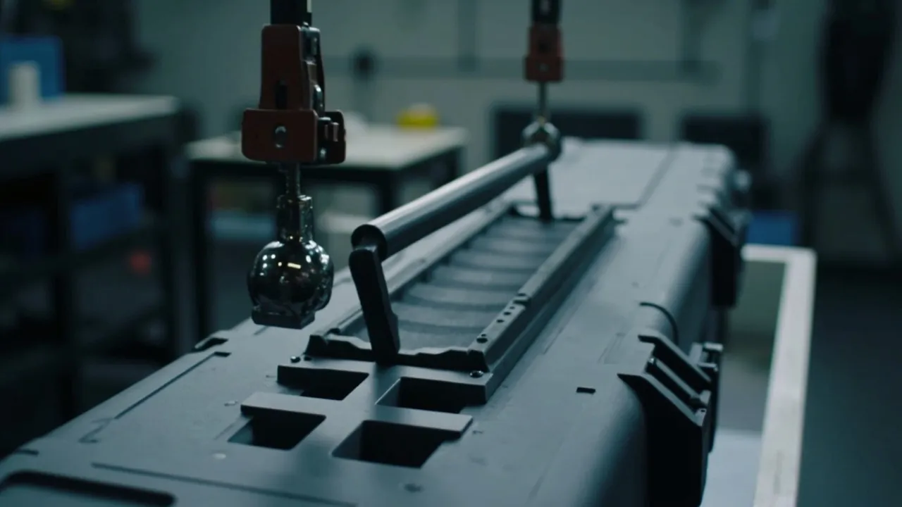
The short answer: a static load test tells you how much a handle can carry; a dynamic load test tells you whether it will survive real handling, drops, vibration and road shock without snapping. The two use different loading methods, different pass criteria and different safety factors. Static testing applies load slowly and holds it, mainly testing strength and creep. Dynamic testing applies load as impact, vibration and repeated cycles, mainly testing impact toughness and fatigue. The most common procurement mistake is using static data to infer real-world safety, or assuming that passing a static test removes the need for a dynamic one. In reality a handle that carries 100 kg in a static test can fracture outright in a single 1.2 m drop, because in polymers strength and toughness are not the same property.
This article builds the complete verification chain for handle load capacity. It first maps the four load paths between a handle and the case shell and the five failure modes that appear in the field. It then sets out the procedures, hold times, loading rates and acceptance rules for static and dynamic testing separately, and uses a comparison table to make the differences unmistakable. It goes on to cover safety-factor conversion, connection design, temperature effects and handle architectures, and finishes with the standards frameworks you can reference and clause wording you can paste into a technical agreement. All numbers are typical or rule-of-thumb values. Real projects must follow the case drawing, physical samples and a mutually agreed test plan.
Table of Contents
- The Bottom Line: Static Sets the Strength Ceiling, Dynamic Sets the Safety Boundary
- Why Handles Fail: Four Load Paths
- Five Typical Failure Modes
- Running a Static Test: Loading, Holding, Judging
- Running a Dynamic Test: Impact, Vibration, Cycling
- Static vs Dynamic: A Direct Comparison
- Setting Safety Factors: Converting Static Data to Dynamic Reality
- The Weakest Link: Where the Handle Meets the Case
- How Temperature Changes Handle Capacity
- Test Focus for Three Handle Architectures
- Equipment and Data Recording Requirements
- Standards Frameworks You Can Reference
- Writing the Clause and the Acceptance Criteria
- Frequently Asked Questions
- Conclusion and Further Reading
The Bottom Line: Static Sets the Strength Ceiling, Dynamic Sets the Safety Boundary
Separating these two concepts is the first step in verifying a handle properly.
Static load is applied slowly and held. The usual method is to ramp from zero to a specified load at a controlled rate, or to load to failure, then hold for a period — commonly one minute, ten minutes, one hour, or even 24 hours — while watching for cracks, permanent deformation or fracture. A static test answers the question: can the structure hold up under steady load?
Dynamic load is applied fast and repeatedly. It includes drop impact, pendulum or falling-weight impact, shaker-table vibration, and lift-and-set-down cycles. A dynamic test answers the question: can the structure survive when energy arrives quickly and again and again?
The physical difference between them is strain rate and energy absorption. Polymers are viscoelastic. Loaded slowly, molecular chains have time to rearrange and the material behaves tougher with higher elongation. Loaded quickly, the chains cannot respond in time and the material behaves stiffer and more brittle. That is why excellent static performance does not imply dynamic safety. What decides an impact outcome is the material's impact toughness (notched impact strength) and whether the geometry gives the material room to deform — not raw strength.
The procurement principle in one sentence: static figures define the nominal load rating; dynamic figures define whether the case can be carried, shipped, and dropped once. Both must be verified separately. If either is missing, you cannot claim the handle has been verified at all.
| Dimension | Static Test | Dynamic Test |
|---|---|---|
| --- | --- | --- |
| Loading rate | Slow (e.g. 10 mm/min) | Fast (impact, drop, vibration) |
| Load character | Constant or slowly varying | Transient, repeated, random |
| Primary evaluation | Strength, stiffness, creep | Impact toughness, fatigue, loosening |
| Typical duration | 1 min to 24 h | Millisecond impacts plus hours of vibration |
| Failure form | Yielding, creep elongation, cracking | Brittle fracture, fatigue cracks, loose joints |
| How results are used | Load ceiling | Service safety boundary |
Why Handles Fail: Four Load Paths
A handle looks like a simple part, but load travels from the palm to the case shell through four paths. Break any one of them and the handle has failed.
Path one: the handle body. From the grip along both arms to the pivot or fixing point. This section mainly carries bending and tension; failure appears as cracking at the mid-span bend or at the base of the arms.
Path two: the handle-to-case connection. This may be a pivot pin, screws, a snap fit, or a thin integrally moulded web. It is the most failure-prone link in the chain because it carries shear, bending and bearing load simultaneously, and its size is usually constrained by wall thickness and packaging space.
Path three: the local structure around the mounting point. Load spreads from the mounting point into the case side wall. Without adequate reinforcement, the load causes local buckling or cracking around the mounting holes.
Path four: the overall case structure. Load finally travels through the case frame. In large cases with insufficient global stiffness, lifting visibly twists the case, so the four corners load unevenly and individual handles become overloaded.
The engineering value of this map is simple: making the handle section bigger only improves path one. It does nothing for paths two, three and four. The field scenario you see most often is a handle that is perfectly strong while the mounting boss on the case cracks first. Verification must therefore treat the handle and case as one system, not test the handle part in isolation. Reinforcement techniques are covered in case reinforcement ribs.
Five Typical Failure Modes
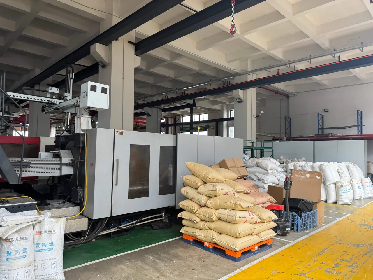
Failure one: cracking at the handle mid-span or bend. Common in polymer handles and more likely at low temperature or under fast loading. Causes are an abrupt wall-thickness change at the bend, an insufficient fillet radius, or the material entering its brittle range in the cold. This failure may not appear at all under static load and only shows up dynamically.
Failure two: pivot pin fracture or pin-hole elongation. When load passes through a small-diameter pin, contact stress is very high. The pin may shear through, and the hole may be crushed into an oval. Once the hole deforms, the handle wobbles and load distribution worsens.
Failure three: mounting boss cracking or screw pull-out. A classic path-three failure. Thin boss walls, missing ribs, and insufficient screw engagement depth all contribute. Under sustained load the polymer also creeps, reducing screw preload and accelerating loosening.
Failure four: tearing at the root of an integrally moulded handle. For thin-web handles moulded into the shell, failure occurs at the root stress concentration. Repeated loading tears it from the root, the same mechanism as a living hinge.
Failure five: creep elongation changing the grip gap. This is not fracture but slow stretching and flattening under long-term static load. The symptom is a degraded grip feel and interference between handle and case. It is a hidden safety threat because there are no obvious warning signs while load capacity steadily drops.
Of these five, only modes one and five are well exposed by static testing. The other three depend far more on dynamic or long-duration testing. That is the fundamental reason both test types are required.
Running a Static Test: Loading, Holding, Judging
A static test is about controlled loading, holding and observation. The details determine whether the data is trustworthy.
Step one: choose the loading method. Three methods are common. First, hang a specified weight from the centre of the handle. Second, use a universal testing machine to pull the handle down at a constant rate. Third, fix the case and pull upward through the handle. The second or third is preferred because it produces a load-displacement curve, whereas hanging weights only gives a qualitative pass or fail.
Step two: set the loading rate. For polymer parts, rate strongly affects the result. 10 mm/min is common, or slower, such as 5 mm/min. Too fast overstates strength; too slow lets creep intervene prematurely.
Step three: define the load levels and hold times. Three levels are typical:
- Rated load (e.g. 1x nominal capacity), held one minute, to confirm everyday capability.
- Safety load (e.g. 2x to 3x nominal), held one minute, to confirm margin.
- Ultimate load (to failure, or 5x and above), to find the true ceiling.
For products that are stored or suspended under load for long periods, add a long-duration static hold, for example 1.5x rated load held for 24 hours or longer, and measure residual deformation after unloading. Polymers creep under sustained load, and short tests cannot reveal it.
Step four: define the acceptance criteria. Use four together:
- No fracture and no through cracks.
- No permanent deformation: residual displacement after unloading does not exceed 1 mm (a rule-of-thumb threshold).
- Connections intact: no plastic bending of the pin, no visible indentations in the pin hole, no loose screws, no cracks in the mounting boss.
- No abnormal case damage: no whitening, cracking or local buckling of the side wall around the mounting area.
Step five: record the environmental conditions. Temperature is a key variable for polymer load capacity, so the report must record ambient temperature and humidity. Cold static tests (for example at -20 °C or -40 °C) require the sample to reach thermal equilibrium before loading.
| Static Test Level | Load (Typical) | Hold Time | Purpose |
|---|---|---|---|
| --- | --- | --- | --- |
| Rated | 1.0x nominal capacity | 1 minute | Confirm everyday capability |
| Safety | 2.0–3.0x nominal capacity | 1 minute | Confirm margin |
| Long hold | 1.5x nominal capacity | 24 hours | Evaluate creep and residual deformation |
| Ultimate | Load to failure | — | Find the strength ceiling and failure mode |
| Cold level | Same load as the equivalent level | Same hold time | Evaluate cold strength reduction |
Running a Dynamic Test: Impact, Vibration, Cycling
Three dynamic loading families are typical, each exposing different failure modes.
Family one: drop impact. Drop a ballasted case from a specified height onto a chosen face, edge or corner. The relationship between drop height and mass is explained systematically in the article on drop height by weight. Drop testing mainly evaluates the handle's impact toughness and the connection's resistance to shock. It is the most effective way to expose brittle fracture risk in polymers, and something a static test cannot replace at all.
Family two: pendulum or falling-weight impact. A known mass swings or falls onto the handle or its immediate surroundings, and the absorbed energy is measured or the damage observed. This applies controlled impact at a specific location, which is more targeted and more repeatable than a whole-case drop. ASTM D880, the standard test method for impact testing of shipping containers and systems, offers a useful model with Procedure A (the container's ability to withstand impacts) and Procedure B (the container's ability to protect its contents).
Family three: vibration and cyclic lifting. Place the case on a shaker table driven with a transport vibration spectrum, or apply repeated lift-and-set-down cycles to the handle. The former mainly reveals latch loosening and global fatigue (see vibration testing and resonance); the latter mainly evaluates the fatigue life of the handle and its connections. A common handle cycle test applies the rated load, lifts and sets down, counts cycles, and watches for when cracking or loosening appears. As a rule of thumb one carry equals one cycle, so if the product is expected to be carried 2,000 times, the cycle test should run at least that order of magnitude.
Dynamic acceptance criteria differ from static. Beyond fracture, you also need to check:
- Whether the handle is still usable after impact (undeformed, does not obstruct lid operation).
- Whether hidden damage exists (internal cracks invisible to the eye, which can be exposed by a repeat static test or dye penetrant inspection).
- Whether connections have loosened (compare fastener torque or gap before and after impact).
- Post-test sealing (if the case is required to be watertight, re-verify sealing after impact).
Static vs Dynamic: A Direct Comparison
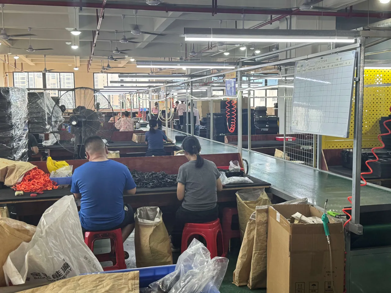
Making the differences explicit is worth more than two sets of numbers in isolation.
| Comparison Dimension | Static Test | Dynamic Test |
|---|---|---|
| --- | --- | --- |
| Loading rate | 5–10 mm/min | Milliseconds for impact; 1–200 Hz for vibration |
| Core metric | Maximum load, residual deformation | Maximum energy survived, cycle life |
| Material property that matters | Tensile strength, modulus, creep modulus | Notched impact strength, elongation at break |
| Temperature sensitivity | Moderate (creep worsens) | Very high (cold brittleness) |
| Can predict brittle fracture | Essentially no | Yes |
| Can predict creep | Yes (with a long hold) | No |
| Typical acceptance | Load value plus hold time | Drop height or energy, plus cycle count |
| Standards logic | ISO 4180 static loading, GB/T 4857 series | ASTM D6179, ASTM D880, ISTA series |
| Procurement use | Set nominal rating and safety factor | Set usage limits and transport risk |
The one thing to take from this table: the two tests evaluate two different material properties — strength and toughness. Strength can be raised by adding wall thickness, ribs or a stiffer material. Toughness can only be raised by choosing the right material system (impact-modified PP, PC/ABS blends) and by designing so the geometry does not create sharp notches and does keep wall thickness uniform. This is why "thicker means more drop-resistant" is a false intuition: thickening raises static strength but can lower impact toughness by worsening cooling uniformity and raising internal stress.
Setting Safety Factors: Converting Static Data to Dynamic Reality
A safety factor is not an arbitrary number. It comes from estimating the dynamic effect.
The basic idea is the equivalent-load method: an impact load in service is modelled as the static load multiplied by a dynamic amplification factor. That factor depends on drop height, cushioning, case stiffness and how well the contents are restrained, and in practice ranges from 2x to more than 10x.
A worked estimate (rule-of-thumb): suppose a loaded case weighs 20 kg total and has two handles, so each carries about 10 kg at rest. Allowing for handling jolts, one-handed pulling that creates off-centre load, and the shock from a 0.5 m drop, the actual peak load may be 4x to 6x static — 40 to 60 kg on each handle momentarily. If the design only proves 20 kg statically and calls it safe, the handle enters the danger zone the moment it is dropped.
On that basis, the usual engineering approach is:
- Nominal capacity set by ergonomics and user comfort, typically not above 15–20 kg for single-handed carrying.
- Static safety factor of 2x to 3x: a handle rated at 10 kg should hold 20 to 30 kg for one minute without deformation.
- Dynamic safety factor of 4x to 6x: it should survive at least one fully loaded drop from a specified height.
- Cycle life set by expected carrying frequency with a 2x margin.
One important caution: a safety factor cannot be achieved by "making the handle chunkier" alone. A thicker handle changes grip feel, adds weight and cost, and does not reduce cold brittle fracture risk — it can raise it. The more effective combination is an impact-modified handle material, generous root fillets, a metal insert or thicker pin at the connection, reinforcement ribs around the case mounting area, and additional handles to share the load.
The Weakest Link: Where the Handle Meets the Case
In field experience, the probability of failure runs from highest to lowest as follows: the connection, the case mounting area, then the handle body.
Why is the connection fragile? Because it is small and highly stressed. The whole bending moment carried by the handle must pass through the connection as shear and bearing load, while the available space is constrained by appearance design and wall thickness. Three approaches are common, each with trade-offs.
Approach one: integrally moulded thin web. The handle is moulded in the same material and shot as the case and relies on a thin web for flexibility and strength. Advantages are low cost, clean appearance and no loose parts. Drawbacks are limited load capacity, short fatigue life and brittle fracture risk in the cold. Suitable for light-duty tool boxes.
Approach two: pivot pin connection. The handle is mounted on pivot seats through a pin. Advantages are clear load paths, replaceability and the ability to design for higher loads. Drawbacks are the space needed for the seats and wear between pin and hole. Improvements are a larger pin diameter, more contact area, a metal pin and a bushing in the hole.
Approach three: metal handle with metal mounting plate. A metal handle is screwed to the case through a metal plate, so the metal parts carry the load and the case only provides fixing points. Advantages are the highest load capacity and the best cold performance. Drawbacks are the need for metal inserts or a thickened mounting area, without which screws pull out. This is the standard approach for heavy-duty and military-spec cases.
Why does the case mounting area also need reinforcement? Because as load spreads from the mounting point it creates local stress concentrations in the side wall. Effective measures include thickening the boss and adding reinforcement ribs, placing mounting points near case edges or corners to exploit structural stiffness, and adding a reinforcing plate outside the mounting area. The general logic is set out in high-strength case structure.
| Connection Type | Load Capacity | Cold Performance | Replaceable | Typical Use |
|---|---|---|---|---|
| --- | --- | --- | --- | --- |
| Integrally moulded thin web | Low | Poor | No | Light-duty tool boxes |
| Pivot pin with polymer seat | Medium | Medium | Yes | General protective cases |
| Pivot pin with metal insert | Medium-high | Good | Yes | Medium and heavy duty |
| Metal handle with metal plate | High | Excellent | Yes | Heavy duty and military spec |
How Temperature Changes Handle Capacity

Temperature is the most overlooked variable in handle verification, and often the most influential.
Cold effects: as temperature falls, polymers become progressively more brittle; impact toughness collapses and elongation at break drops. A handle that survives a drop at room temperature can fracture in a single drop at -40 °C. Any case destined for cold regions, cold chain, air freight (cold at altitude) or winter outdoor use must be tested dynamically in the cold. Judgement methods and standards are covered in low-temperature brittleness testing.
Heat effects: at high temperature the polymer modulus falls and the material softens, so creep accelerates. The symptom is slow stretching or even permanent deformation under static load, which is especially dangerous for long-term suspension. Heat also reduces screw preload under sustained load, causing connections to loosen.
Thermal cycling effects: repeated high-low cycling creates differential thermal expansion between dissimilar materials (polymer and metal insert, handle and shell). Alternating stress develops at the interface and can eventually cause cracking or loosening over time. This matters particularly for metal insert designs.
Engineering recommendation: temperature conditions must be written into the test plan, covering at least ambient, cold (-20 °C or -40 °C depending on the market) and hot (+55 °C or +70 °C), and loading must begin only after the sample has reached thermal equilibrium — not immediately after removal from the chamber.
Test Focus for Three Handle Architectures
Integrally moulded thin-web handles. Handle and case are the same material, moulded in the same shot, with a thinned web at the root. The test focus is root fatigue and cold brittle fracture. Static testing should watch for stress whitening at the root; dynamic testing should include a cold drop. Nominal capacity for this type should be conservative.
Pivoting handles. The handle rotates about a pin, folding flat against the case face when stowed and swinging out for use. The test focus is pin shear strength, hole wear and fatigue of the swing action. Because the swing action is repeated, add a swing cycle test. The durability logic mirrors that of latch life testing.
Telescopic trolley handles with wheel integration. Common on wheeled cases, with handle and trolley integrated. The test focus is smooth operation of the telescopic mechanism under load, strength of the trolley-to-case connection, and reliable load transfer when switching between carrying and towing. These structures require a substantially larger test scope than a simple handle and need their own test plan.
What all three share is that they must be tested as a system, not as separate parts. Handle, connection and case mounting area behave as one unit; strength data for the handle alone has no engineering meaning.
Equipment and Data Recording Requirements
Typical equipment list:
- Universal testing machine with load and displacement sensors, for static testing and load-displacement curves.
- Drop tester with adjustable height and attitude (face, edge, corner), for whole-case drop impact.
- Impact apparatus, pendulum or falling weight, for targeted impact.
- Shaker table, for transport vibration simulation.
- Thermal chamber, for static and dynamic testing at temperature.
- Torque wrench and feeler gauges, for measuring connection torque and gaps.
Data recording requirements:
- Sample information: batch, material grade, structural revision, production date.
- Environmental conditions: temperature, humidity and thermal soak time.
- Loading conditions: method, rate, load level, hold time, or drop height, impact energy and vibration spectrum.
- Raw data: load-displacement curve, peak load, photographs of the failure location.
- Result: a conclusion against each of the four criteria.
- Failure description: location, mode (brittle fracture, yielding, tearing, loosening) and whether there were precursors.
One important procedural requirement: always repeat a static test after a dynamic test. Impact can cause internal damage invisible to the eye, and the repeat static test exposes it. If static strength after impact is clearly lower than before, the part is internally damaged and should not be accepted even if it looks intact.
Standards Frameworks You Can Reference
Handle load testing likewise has no dedicated protective-case standard, so practice is to borrow general packaging and transport test standards and add a custom test plan.
- ASTM D6179 — the standard test method for drop testing of loaded containers and systems, the main source for evaluating handles in a drop scenario.
- ASTM D880 — the standard test method for impact testing of shipping containers and systems; Procedure A tests the container's ability to withstand impacts, Procedure B tests its ability to protect contents. Both are useful models for handle impact testing.
- ISO 4180 — test schedules for complete, filled transport packages, providing a full-package evaluation framework.
- The GB/T 4857 series — basic test methods for transport packages, covering drop, stacking and vibration. This is the domestic general framework in China; the stacking methods relate to stacking load testing.
- ISTA 1A, 2A and 3A — transport test procedures whose drop and vibration stages indirectly challenge handle reliability in transit; see ISTA transport testing.
- MIL-STD-810H — environmental test methods; the logic of shock (Method 516) and vibration (Method 514) transfers well; see MIL-STD-810H compliance.
- ISO 812 and GB/T 15256 — determination of low-temperature brittleness of vulcanised rubber, used to judge gasket brittleness in the cold.
- ISO 974 — determination of the temperature of embrittlement of plastics by impact, used to find the brittle transition temperature of the handle material and to set cold test conditions.
- GB/T 2828.1 — sampling procedures for inspection by attributes, for sample size and acceptance numbers.
- ISO/IEC 17025, CNAS and CMA — determine whether a test report carries accreditation backing; see the guide to reading test reports.
| Standard / Document | Test Stage | Purpose |
|---|---|---|
| --- | --- | --- |
| ASTM D6179 | Drop impact | Set drop height and attitude |
| ASTM D880 | Impact | Targeted impact loading method |
| ISO 4180 | Overall test schedule | Plan combined testing |
| GB/T 4857 series | Drop, stacking, vibration | Domestic general test methods |
| ISTA 1A / 2A / 3A | Transport | Transport reliability verification |
| ISO 974 | Material embrittlement temperature | Set cold test conditions |
| GB/T 2828.1 | Sampling | Determine sample size |
Writing the Clause and the Acceptance Criteria
Clear wording prevents arguments at acceptance. Six clauses work well.
Clause one, structure and count. "The case is fitted with X handles, architecture XX (integral / pivoting / telescopic), handle body material XX, connection type XX."
Clause two, nominal capacity. "Nominal capacity per handle not less than XX kg; nominal whole-case lifting capacity not less than XX kg." (Nominal capacity should follow ergonomics and real user behaviour.)
Clause three, static conditions and criteria. "At 23 ± 2 °C, load at 10 mm/min to X times nominal capacity and hold for one minute; residual displacement after unloading not more than 1 mm; no cracks, no permanent deformation, no loosened connections, no damage to the case mounting area."
Clause four, dynamic conditions and criteria. "Perform one fully loaded drop at -20 ± 2 °C (after thermal soak) and one at ambient, at a height of XX mm. After the drop, the handle shows no fracture or cracking and remains usable; a repeat static test shows no more than XX percent loss of strength."
Clause five, cycle life. "Perform at least XXXX lift-and-set-down cycles at rated load; after cycling, no cracks, no visible loosening, and change in handle-to-case gap not exceeding XX mm."
Clause six, reporting and accreditation. "The supplier shall provide a test report including raw data (load-displacement curves, failure photographs, temperature records). If testing is outsourced, the laboratory shall hold ISO/IEC 17025 accreditation."
The value of these six clauses is that they turn "the handle is strong" from a subjective statement into a reproducible, judgeable engineering condition. Handle system design capability is also an important indicator of an OEM factory's competence.
Frequently Asked Questions
Q: What static and dynamic values are reasonable for a handle?
A: Set them in three layers: nominal capacity, static factor and dynamic factor. First, nominal capacity follows real use and ergonomics — single-handed carrying is generally comfortable up to 15–20 kg, beyond which users instinctively use both hands or cradle the case, so an inflated nominal value serves no purpose. Second, the static factor should be 2x to 3x nominal: at 23 °C the handle should accept 2x to 3x nominal at 10 mm/min and hold one minute without permanent deformation. Third, the dynamic factor should be 4x to 6x: it should survive at least one fully loaded drop from a specified height without failing. That height follows product positioning and target market — lower for light-duty tool boxes, higher for heavy-duty and military-spec cases — and can be cross-checked with the method in drop height by weight. There is also a fourth layer: cycle life, set by expected carrying frequency with a 2x margin. Only all four together constitute complete load verification; missing any one layer is not enough to support a claim that the handle is reliable.
Q: Why does a handle that passes static testing break after a drop?
A: Because static and drop testing evaluate two different mechanical properties. Static testing mainly reflects strength and stiffness: loaded slowly, polymer chains have time to rearrange, so the material shows higher elongation and better toughness and can carry a larger steady load. A drop is millisecond-scale impact loading, so strain rate is extremely high and the chains cannot respond; microscopically the material becomes more brittle and elongation at break falls. At the same time, impact creates local stress concentrations at notches, fillets and weld lines, where energy density is far higher than under static load. If the geometry gives no room for deformation — for example an undersized root fillet or an abrupt wall change — impact energy cannot dissipate through plastic deformation and is released as a crack. Low temperature amplifies this considerably. The correct conclusion is not that static testing is unnecessary, but that static data can only set the nominal rating, never predict drop resistance. Drop resistance can only be judged by dynamic testing.
Q: Which handle-to-case connection is most reliable?
A: In descending order of load capacity: a metal handle with a metal mounting plate; a pivot pin with a metal insert; a pivot pin with a polymer seat; and an integrally moulded thin web. The metal option is most reliable not simply because "metal is stronger" but because it moves the load into the metal parts so the case only provides fixing, avoiding creep and brittle fracture of polymer under high stress. Next is the pivoting handle with metal inserts, where the insert spreads screw or pin load over a larger polymer area and greatly reduces local stress. Polymer pivot seats suit medium and light loads, provided the mounting boss is thickened, reinforcement ribs are added and the pin diameter is increased to lower stress. An integrally moulded thin web suits light-duty tool boxes, but its reliability depends heavily on material and design and its cold-weather risk is the highest. Whichever option is chosen, add reinforcement outside the mounting area, because the load must ultimately spread into the case side wall.
Q: How many handles should a case have?
A: It depends on weight, dimensions and how the case is used. Practical guidance: up to about 5 kg total, one handle is usually enough; 5 to 15 kg, at least one main handle, with an auxiliary or side handle considered; 15 to 30 kg, two handles arranged symmetrically; above 30 kg, two or more handles with wheels and a trolley, or a two-person carry design. Three placement rules: arrange symmetrically to prevent tilting; keep the handle axis close to the case centre of gravity plane to prevent swinging; and place mounting points near load-bearing structure such as edges, corners or reinforced zones so load goes straight into structure rather than through a flat panel. A practical check: divide total weight by handle count to get average load per handle, multiply by the dynamic amplification factor (4x to 6x in practice), and if the resulting peak exceeds half the measured static capacity of the handle, add handles or strengthen the structure.
Q: How much does cold reduce handle capacity?
A: The reduction depends on the material system and cannot be generalised, but the direction is unambiguous: the colder it gets, the more impact capacity falls, while static capacity falls relatively mildly. As a rule of thumb, a standard polypropylene handle taken from ambient to -20 °C may lose 40 to 60 percent of its impact capacity; at -40 °C the loss can exceed 70 percent, and the failure mode changes from yielding to brittle fracture. Impact-modified materials such as toughened PP or PC/ABS blends improve cold impact performance significantly but raise cost. Static capacity in the cold usually does not fall and may even rise, because the material becomes harder and stronger — but that added strength is a consequence of increased brittleness and is unfavourable for drop scenarios. Cold verification should therefore focus on dynamic rather than static testing. Note that the sample must reach thermal equilibrium in the cold environment before loading; testing immediately after removal overstates capacity because the surface warms up. Material embrittlement temperature can be determined following the ISO 974 method.
Q: How many cycles should a handle cycle test run?
A: Set it from expected carrying frequency with margin. Estimate: daily carries times years of service times working days per year. For example, three carries a day over five years at 250 working days is about 3,750 cycles; add a 2x margin and set a target around 8,000 cycles. Tiered guidance: long-term storage (under 0.5 carries per day) may need only a few hundred; general industrial use (one to three per day) about 1,000 to 4,000; high-frequency handling (five to ten per day) about 6,000 to 12,500; and extreme logistics scenarios (over 20 per day) should exceed 25,000 cycles and should consider a metal handle. Cycle testing should use rated load rather than no load, and should periodically check connection torque and gap, because these hidden forms of degradation often appear earlier than cracking of the handle body. Finish with a repeat static test to expose internal delamination or microcracks.
Q: Can a handle become a load-bearing point during stacking or transport?
A: Yes, and it is frequently overlooked. In stacking, if a handle protrudes beyond the case surface or is not securely stowed, a lower handle can become a support point, concentrating pressure that should be carried by the wall panel into a small area, causing local damage to handle or case. In transport, a loose or swinging handle collides repeatedly with other cases or packaging. Handle design should therefore stow flush with or below the case surface, with a reliable lock to prevent it swinging open in transit. Correspondingly, whole-case stacking verification should cover both "handle stowed" and "handle deployed" states; how to set stacking load is covered in stacking load testing. If the product will be stacked in transit, add a clause stating that the handle must stow within the case envelope.
Q: How do I know when a handle needs replacing?
A: Four field checks work well. First, look at grip and appearance: obvious whitening (stress whitening), visible cracks, permanent bending or fine surface crazing means immediate replacement. Second, check the connection: visually and by hand, if the handle is clearly loose, or the pin has migrated, a screw has loosened, or cracks appear around the mounting seat, the connection has degraded. Third, measure gap and length: compare a used case against a new one; visible handle elongation or an increased gap indicates creep damage. Fourth, do a simple load check: with a spotter present, lift briefly with slightly more than nominal load; any abnormal noise, visible deformation or failure to recover means stop using it. Note that any one abnormal finding should trigger replacement of the whole set (where multiple handles are fitted), because parts from the same batch are usually at a similar stage of degradation, and replacing only one redistributes load and overloads the rest.
Q: How do I write handle load requirements into a technical agreement for a custom case?
A: Six clauses work well. Clause one, structure and count: "The case is fitted with X handles, architecture XX, handle body material XX, connection type XX, connector material XX." Clause two, nominal capacity: "Nominal capacity per handle not less than XX kg; nominal whole-case lifting capacity not less than XX kg." Clause three, static conditions and criteria: "At 23 ± 2 °C, load at 10 mm/min to X times nominal and hold one minute; no cracks, no permanent deformation (residual displacement 1 mm or less), no loosened connections, no damage to the case mounting area." Clause four, dynamic conditions and criteria: "One fully loaded drop at ambient and one at -20 ± 2 °C, height XX mm; after the drop, no fracture and still usable; repeat static test shows no more than XX percent loss." Clause five, cycle life: "At least XXXX lift-and-set-down cycles at rated load; after cycling, no cracks and gap change not exceeding XX mm." Clause six, reporting: "Provide a report with raw data; third-party laboratories shall hold ISO/IEC 17025 accreditation." It is also worth adding a stowability clause: "The handle shall stow within the case envelope and include a lock to prevent it swinging open in transit."
Conclusion and Further Reading
Returning to the title question: the difference between static and dynamic handle verification is not the size of the load but the loading method and the property being evaluated. Static testing loads slowly and holds, evaluating strength, stiffness and creep, and is used to set nominal capacity and safety factors. Dynamic testing applies impact, vibration and cycles, evaluating impact toughness and fatigue, and is used to set the service safety boundary. Three steps get this right. First, verify the handle, the connection and the case mounting area as one system rather than testing the handle part alone. Second, set four layers of criteria — 1x nominal, 2x to 3x static, 4x to 6x dynamic, and cycles based on real carrying frequency with a 2x margin. Third, treat temperature as a separate condition and never omit the cold dynamic round.
Three recommendations you can act on immediately. First, static data can only set nominal capacity and must never be used to infer drop resistance, because in polymers strength and toughness are not equivalent. Second, the part that most needs strengthening is the connection and the case mounting area, not the handle body — enlarging the handle section does not help there. Third, always repeat a static test after a dynamic test to expose internal damage invisible to the eye.
JUNZHJIA, manufactured by KeXin New Materials (Guangdong) Co., Ltd., produces protective cases, tool boxes, military-spec storage boxes and waterproof junction boxes for wholesale, distribution, OEM and ODM customers worldwide. The company configures integral, pivoting and metal handle options to customer loads and use scenarios, with metal inserts, thicker pivot pins and reinforced structures, and supports test plan development for static, dynamic, cold and cyclic programs, along with test documentation.
Further Reading