


The short answer: drop height is not chosen by feel. It follows from three things — the total weight of the shipping unit, the drop orientation, and the handling scenario the product actually meets. The governing rule is that heavier packages drop from lower heights, because people lift heavy loads less high and heavy units tend to land flat rather than on a corner. The banded tables in ISTA 1A and ASTM D4169 are the industry's most common starting point: below 9.1 kg use 762 mm; 9.1–18.2 kg use 610 mm; 18.2–27.3 kg use 457 mm; 27.3–45.4 kg use 381 mm; 45.4–68 kg use 305 mm; above 68 kg the figure usually falls to 203–254 mm. But a banded table is only the starting point. The final number has to come back to the life cycle profile: single-parcel courier shipping, palletised less-than-truckload freight, in-vehicle carriage, or manual handling. This article sets out a reproducible way to fix the height, the orientation rules, the low-temperature preconditioning logic, the pass thresholds, and a drop test checklist you can put in front of a supplier or a lab.
A drop test looks like the simplest item in the packaging test catalogue: lift the case, release it, let it land, then check whether anything broke. Precisely because it looks simple, it is also the test most often performed carelessly. The failures cluster in three places. First, the height is decided on the spot — 1.2 m today, 0.8 m tomorrow — so reports from different batches cannot be compared. Second, only one face is dropped, which ignores corner and edge drops, the two orientations that concentrate stress hardest. Third, no temperature preconditioning is performed, so the case is only dropped at room temperature; the moment a cold chain or high-altitude scenario appears, brittle cracking shows up. All three share one root cause: treating drop height as a negotiable adjective instead of a design parameter that has to be derived.
This guide is written for procurement, structural and quality staff working with protective cases, tool cases and military-spec storage boxes. It breaks down the basis for fixing drop height, the inverse relationship between weight and height, orientation and drop sequence, the correspondence between international and Chinese standards, and the special logic that applies to a protective case, which is simultaneously a package and a product. All figures are described as typical or empirical, and the binding test conditions are whatever the two parties confirm in the test plan against the released standard.
Contents
- What a drop test actually measures: three physical quantities and one pass line
- Why heavier packages drop from lower heights
- The ISTA 1A weight-banded drop height table
- The height logic behind ASTM D4169 and ISO 4180
- GB/T 4857.5 and Chinese packaging drop testing
- Drop orientation: corner, edge, face
- Translating protective case scenarios into heights
- How MIL-STD-810H Method 516 relates to drop testing
- Temperature preconditioning: the cold drop is the harshest one
- Pass criteria and the inspection checklist
- How material and structure change the result
- Writing an executable drop test plan
- Common misunderstandings and traps
- Frequently Asked Questions
- Conclusion and Related Reading
What a drop test actually measures: three physical quantities and one pass line
A drop test applies a reproducible mechanical shock to a shipping unit and then observes whether the package and its contents still perform as intended. Three physical quantities govern the outcome:
- Drop height h (mm or m) — this fixes the impact velocity at the moment of landing.
- Total mass of the shipping unit m (kg) — case, liner and contents together; none can be omitted.
- Drop orientation (corner, edge, face) — this decides how the impact energy is distributed over the contact area, and therefore how severely stress concentrates.
The relationship between height and velocity comes from free fall: v = sqrt(2gh) with g taken as 9.81 m/s². At the instant of landing the kinetic energy equals the potential energy, so E = mgh. This explains a fact that is frequently overlooked: doubling the height multiplies velocity by only about 1.41, but it genuinely doubles the impact energy. That is why every standard tabulates height rather than velocity — height is a more intuitive and more direct proxy for energy control.
| Drop height | Theoretical impact velocity | Relative impact energy | Typical scenario (empirical) |
|---|---|---|---|
| --- | --- | --- | --- |
| 203 mm | approx. 2.0 m/s | 1.0x | Heavy unit set down at low level |
| 305 mm | approx. 2.4 m/s | 1.5x | Unit released from knee height |
| 457 mm | approx. 3.0 m/s | 2.3x | Taken from a seat or low shelf |
| 610 mm | approx. 3.5 m/s | 3.0x | Slips from waist height |
| 762 mm | approx. 3.9 m/s | 3.8x | Bench or work surface drop |
| 1016 mm | approx. 4.5 m/s | 5.0x | Slips from chest height |
Velocities are theoretical; real impact velocity deviates slightly because of air resistance and rotational attitude. Energy multiples are indexed to 203 mm.
The pass line normally has three parts: the package survives, the contents survive, and function is retained. For a protective case there is an additional criterion that matters just as much — the case still meets its declared ingress protection rating after the drop. A case that passed IP67 before the drop and takes in water afterwards has, in packaging terms, "passed", yet in product terms it has failed. That additional criterion must be written into the test plan, otherwise the most damaging failure chain goes untested. The full definition and verification route for IP67 is covered in IP67 protective case design and verification and what an IP67 rating actually means.
Why heavier packages drop from lower heights
The point that puzzles newcomers most is this: heavy things cause more damage when they land, so why do the standards make them fall from lower heights? There are three layers to the answer, and all three point the same way.
The first layer is human handling behaviour. A person's lifting capability falls sharply as load increases. Light cases can be raised overhead or placed on a high shelf, so the drop starts from higher up; heavy cases are lifted from the floor or from low levels, so the drop starts lower to begin with. The banded tables in ISTA and ASTM are not "going easy" on heavy goods; they are a statistical reconstruction of how handling actually happens.
The second layer is impact energy and peak force. At the same drop height, greater mass means greater kinetic energy at landing and therefore greater peak force in the structure. If a 68 kg unit and a 5 kg carton were both dropped from the same height, the structural damage from the former would be an order of magnitude greater. So from the standpoint of controlling the severity of a single impact, heavy units must be paired with lower heights to bring impact severity back into a comparable range.
The third layer is orientation and rotation. Heavy units have a high centre of gravity and large inertia, so they tend to land flat rather than on a corner. That reduces stress concentration but increases the contact area and the risk of global deformation. Light units, by contrast, are more easily spun when thrown or knocked, so they land on a corner or edge and produce extremely high local stress. This is exactly why light packages need the fuller corner, edge and face combination.
| Weight band (including contents) | Typical handling | Typical drop origin | Note |
|---|---|---|---|
| --- | --- | --- | --- |
| Below 5 kg | One hand, sometimes tossed | 1.0–1.2 m | Rotates easily, high corner-drop probability |
| 5–15 kg | Two hands or shoulder | 0.8–1.0 m | Corner and face drops both relevant |
| 15–30 kg | Two hands or two people | 0.6–0.8 m | Face and edge drops dominate |
| 30–70 kg | Two people or mechanical aid | 0.3–0.5 m | Mostly face drops |
| Above 70 kg | Pallet and forklift | 0.2–0.3 m | Focus shifts to stacking and tip-over |
The banded table gives a typical starting point, not a ceiling. If a product will be air-dropped, thrown around in a vehicle, or fall from high racking, the conditions must be tightened for that specific scenario rather than copied from the weight band. Related transport risks are covered in how to secure a case in transport.
The ISTA 1A weight-banded drop height table
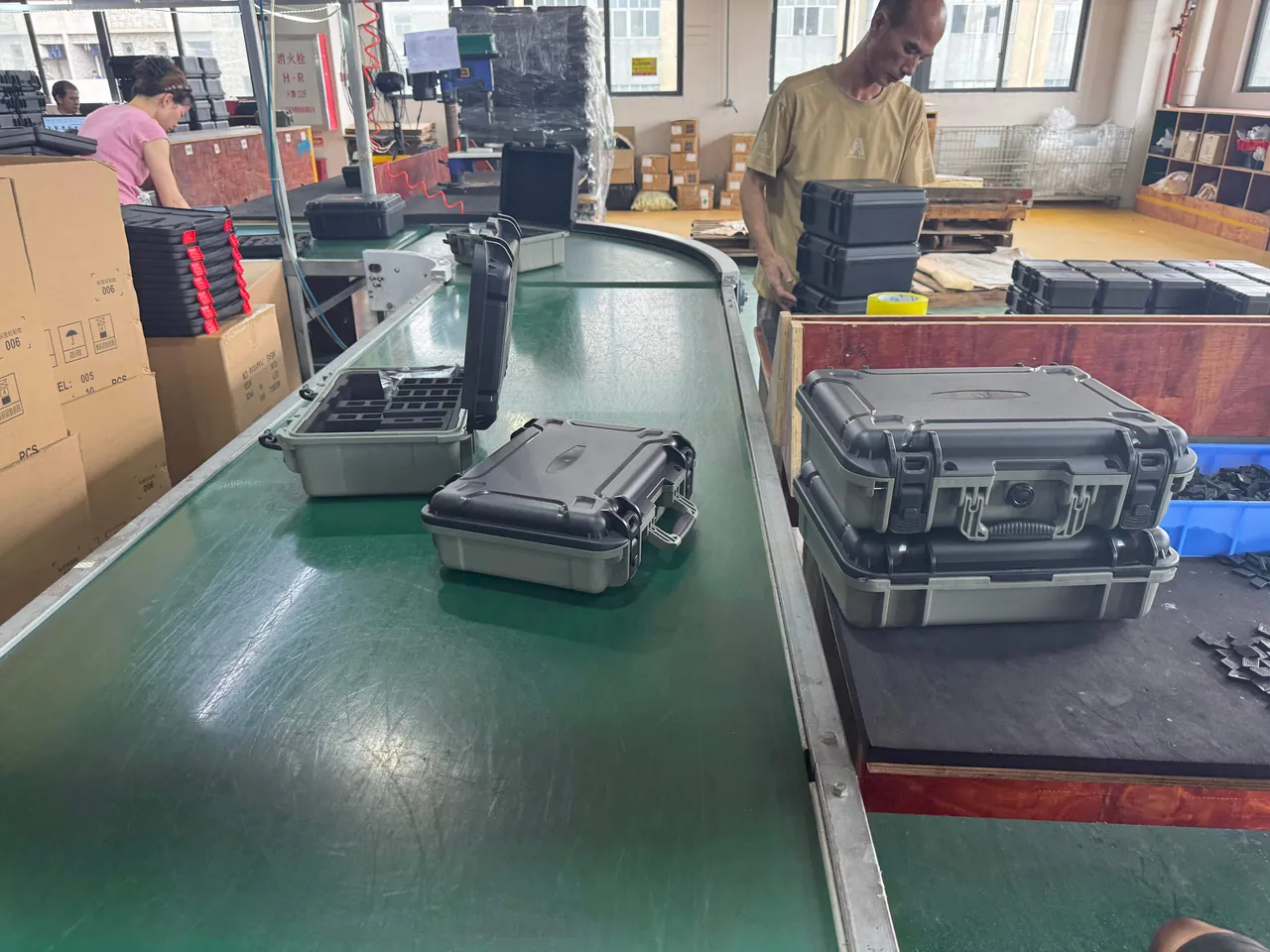
The ISTA 1 series consists of non-simulation integrity tests, and ISTA 1A is the most widely quoted basic procedure. It applies to a single shipping unit and does not differentiate between transport modes; it simply checks whether the unit can survive at all. It has two parts: fixed-displacement vibration and drop. The drop portion assigns a height by weight band and uses a fixed orientation sequence of one corner, three edges and six faces.
| Total shipping unit weight | Typical ISTA 1A drop height | Note (empirical) |
|---|---|---|
| --- | --- | --- |
| 0–9.1 kg (0–20 lb) | 762 mm (30 in) | Light unit, highest corner-drop risk |
| 9.1–18.2 kg (20–40 lb) | 610 mm (24 in) | Typical two-hand lifting band |
| 18.2–27.3 kg (40–60 lb) | 457 mm (18 in) | Usually needs two people |
| 27.3–45.4 kg (60–100 lb) | 381 mm (15 in) | Edge and face drops dominate |
| 45.4–68.0 kg (100–150 lb) | 305 mm (12 in) | Mechanical aids become common |
| 68.0–90.7 kg (150–200 lb) | 254 mm (10 in) | Heavy units |
| Above 90.7 kg (200 lb) | 203 mm (8 in) | Stacking and tip-over become primary |
How should this table be used? Three points. First, take the total shipping unit weight, not the bare case weight. If the contents weigh 20 kg and the case with liner weighs 4 kg, the unit is 24 kg, which falls in the 18.2–27.3 kg band and gives 457 mm. Second, the figures represent the minimum complete 1A test; dropping a single face does not constitute a pass. Third, if the product ships as a single parcel and passes through parcel sortation, the procedure should be upgraded to ISTA 2A or 3A, whose drop sequences track real logistics more closely — the differences are set out in how ISTA transport testing is performed.
A weight band only answers "how high", never "how many times" or "in which orientation". A drop report that states a height but omits orientation and repetition count is still not reproducible and still cannot support an engineering judgement.
The height logic behind ASTM D4169 and ISO 4180
If ISTA is the practical procedure written for shippers, ASTM D4169 is the scenario-based system written for engineering verification. Its core concept is the Distribution Cycle (DC), which numbers logistics chains from DC 1 to DC 18. Each DC specifies an applicable scenario and test sequence. The most familiar case — a single parcel under 68 kg — corresponds to DC 13, while palletised less-than-truckload freight falls under a different DC.
D4169 also introduces Assurance Level (AL), which applies the same test conditions at three levels of severity:
| Assurance level | Meaning | Applies to | Effect on drop height |
|---|---|---|---|
| --- | --- | --- | --- |
| AL I | Most severe | High value, critical, irreplaceable goods | Highest height, most repetitions |
| AL II | Standard | Ordinary commercial goods | The industry default |
| AL III | Least severe | Low value, damage-tolerant goods | Lowest height |
ISO 4180 is the International Organization for Standardization's general rules for compiling performance test schedules for complete, filled transport packages. Its value lies in organising weight, dimensions and transport mode into a selectable rule set, and it is often used as the scheduling basis inside ISO-based systems. The relationship between the three is best understood this way: ISO 4180 supplies the rule framework, ASTM D4169 supplies the scenario numbering and severity levels, and ISTA supplies plug-and-play operational procedures. For a specific project, which one to cite depends on the customer contract and the conventions of the target market, not on which one sounds more advanced.
For a protective case the most practical approach is this: use ASTM D4169 DC 13 with a stated assurance level for single-parcel scenarios in North America, use ISTA 3A for general parcel shipment, and cite ISO 4180 when an internationally standardised test schedule is required. Drop heights from the three can corroborate each other, but they must not be mixed when describing a single test.
GB/T 4857.5 and Chinese packaging drop testing
Transport packaging testing in China is handled by the GB/T 4857 series, which mirrors the structure of the ISO 4180 family. The part directly concerned with drop testing is GB/T 4857.5, "Packaging — Basic tests for transport packages — Part 5: Drop test method", which specifies how face drops, edge drops and corner drops are performed, including equipment, release method, impact surface requirements and orientation definitions.
One point deserves emphasis: GB/T 4857.5 states how to drop; the drop height itself is fixed by the product standard or the customer according to the test schedule. In Chinese projects the usual route is therefore to first condition the specimen under GB/T 4857.2 for temperature and humidity, then execute the drops to 4857.5 at the agreed heights and orientations, and finally issue the report under the recording requirements of 4857.1. If the customer wants a full vibration and stacking combination, 4857.7 for sinusoidal vibration, 4857.10 for fixed-frequency sinusoidal vibration, 4857.23 for random vibration, and 4857.3 and 4857.4 for stacking and compression will also be invoked.
| Standard | Scope | Relationship to drop testing |
|---|---|---|
| --- | --- | --- |
| GB/T 4857.2 | Temperature and humidity conditioning | Preconditioning before drops |
| GB/T 4857.5 | Drop test method | Implementation of face, edge and corner drops |
| GB/T 4857.7 / .10 / .23 | Vibration tests | Combine with drops into a transport sequence |
| GB/T 4857.3 / .4 | Stacking and compression | Frequently combined with drops in a full schedule |
So when a domestic customer asks for "a drop test to the national standard", the technically correct response is to confirm that GB/T 4857.5 governs the method while asking the customer to supply or confirm the height table and test schedule — there is no universal height built into the method itself. If the customer has no schedule, an ISTA or ASTM banded table is a reasonable starting point for negotiation, to be tailored afterwards against the agreed life cycle profile.
Drop orientation: corner, edge, face
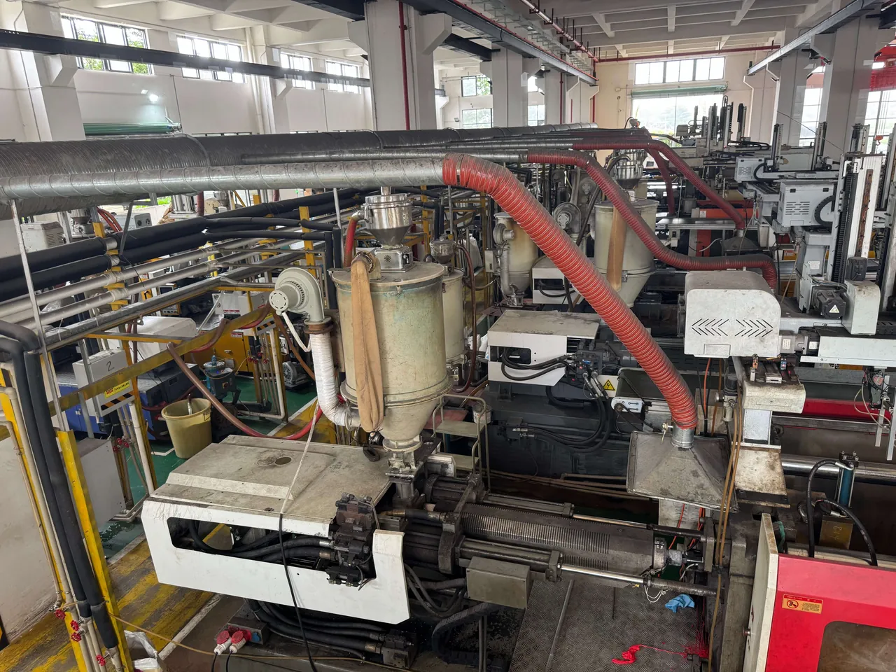
Height answers how far the unit falls; orientation answers how it lands. The same case dropped from the same height can show a structural response several times more severe when it lands on a corner rather than a face.
- Face drop — the largest flat surface contacts the floor. Impact force is spread over a wide area, peak stress is relatively low, but global deformation and lid displacement are larger.
- Edge drop — one edge contacts the floor. Stress concentrates along a very small contact line, and this is a common cause of shell cracking and latch misalignment.
- Corner drop — a single corner contacts the floor. Contact area is minimal and stress concentration is the most severe of the three. It exposes structural weaknesses in the corner geometry and reinforcement ribs faster than anything else.
ISTA 1A uses the classic combination: drop the most vulnerable corner first, then the three edges radiating from that corner, then all six faces — ten drops in total. The order is not arbitrary; it is a strategy of tightening first and covering afterwards. The corner establishes the structural limit under the harshest condition, and the face drops then check overall stiffness and lid retention.
| Orientation | Contact characteristic | Stress concentration | Main failure mode | Recommended order |
|---|---|---|---|---|
| --- | --- | --- | --- | --- |
| Corner drop | Single point | Highest | Corner cracking, rib fracture | Drop 1 |
| Edge drop | Line contact | Medium to high | Shell cracking, latch misalignment | Drops 2–4 |
| Face drop | Surface contact | Moderate | Lid displacement, seal deformation | Drops 5–10 |
For a sealed protective case, it is worth adding a seal check after the corner and edge drops and before the face drops, so that you can tell whether the impact has already disturbed the flatness of the case rim. Seal material and compression design are covered in how to select case seal materials and waterproof design for outdoor cases.
Translating protective case scenarios into heights
The biggest difference between a protective case and ordinary packaging is that the case is both the package and the product. A carton that fails can be discarded and replaced; a protective case that fails must keep serving, and the equipment inside must still work. Its drop height therefore cannot be derived from logistics bands alone; it has to be derived from the scenario. The table below gives common scenarios and typical height ranges.
| Scenario | Typical drop origin | Basis | Note |
|---|---|---|---|
| --- | --- | --- | --- |
| Slips while carried by hand | 1.0–1.2 m | Human dimensions | The most common everyday drop |
| Slips while the lid is open | 0.8–1.2 m | Human dimensions | The lid often lands first |
| Unloading from a truck bed | 1.0–1.5 m | Vehicle dimensions | High centre of gravity, tends to rotate |
| Thrown around inside a moving vehicle | 0.5–1.0 m (repeated) | Road condition statistics | Repeated impact and fatigue matter |
| Handling on a ship or offshore platform | 0.5–1.5 m | Working environment | Often combined with salt fog testing |
| Work at height or helicopter sling | 1.5 m and above | Working environment | Must be tailored per project |
A sensible sampling strategy is to take the heaviest typical model and the lightest typical model from the range and run a full drop set on each. The heaviest model stresses structural strength and latch retention; the lightest model stresses corner-drop stress concentration. If the customer has a defined mission profile, add drops at the weight and height that profile specifies. Drop testing usually needs to be combined with stacking and vibration into a full transport sequence; the combinations are described in how stacking load testing works and vibration testing and transport resonance.
How MIL-STD-810H Method 516 relates to drop testing
Military, law enforcement and premium equipment programmes frequently require compliance with MIL-STD-810, and the method most relevant to drop testing is Method 516, Shock. It contains two procedures:
- Functional Shock — verifies that equipment continues to operate after an impact.
- Crash Safety — verifies the safety margin in a crash event and is destructive.
The division of labour between Method 516 and ISTA or ASTM drops is clear. Method 516 addresses how a complete equipment item responds to a realistic shock spectrum, usually defined by a shock spectrum or by a drop height combined with an orientation. ISTA and ASTM address whether a shipping unit can pass through the logistics chain, defined by weight bands and fixed orientation combinations. They cannot substitute for each other, but together they form a complete evidence chain: ISTA or ASTM demonstrates that the package survives transport; 810 Method 516 demonstrates that the product survives use.
At report level, both can be complemented by IEC 62262 / IK ratings. An IK rating classifies an enclosure using a single-point impact of calibrated energy, answering "what impact can the enclosure take". A drop test answers "from what height can it fall and still work". The verification logic for the three is consistent; for the full picture on IK see IK ratings and impact protection explained, and for the overall military framework see how cases comply with MIL-STD-810.
Temperature preconditioning: the cold drop is the harshest one
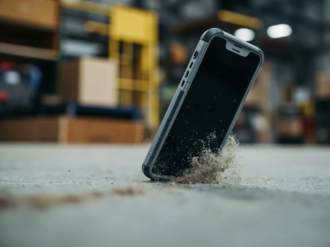
If only one engineering recommendation could be made here, it would be this: always precondition the drop test at low temperature. Most engineering plastics have a ductile-to-brittle transition temperature, below which the material changes from ductile to brittle fracture and its impact absorption falls sharply. A case that survives a 305 mm drop at room temperature may crack along its corner from the same height after conditioning at −20 °C, rather than merely denting.
| Preconditioning | Material state (empirical) | Typical drop result | Applicable scenario |
|---|---|---|---|
| --- | --- | --- | --- |
| Ambient, about 23 °C | Good ductility | Local denting, elastic recovery | Ordinary indoor logistics |
| Around 0 °C | Ductility slightly reduced | Deeper dents, possible fine cracks | Refrigerated transport |
| −18 °C to −20 °C | Clearly embrittled | Corner cracking, edge fracture | Cold chain, cold outdoor use |
| −40 °C and below | Highly embrittled | Extensive brittle fracture, latches may shear | Polar regions, aircraft cargo holds |
Three implementation points. First, the preconditioning temperature should match the target scenario: −18 °C is common for cold chain, while −20 °C to −40 °C applies to cold climates and aircraft cargo holds. Second, soak time must be sufficient for the whole specimen to reach thermal equilibrium; as a rule of thumb it is calculated from wall thickness and generally runs 8–24 hours. A specimen that is only surface-cooled will give an optimistic result. Third, transfer time must be controlled — the interval from removing the specimen from the chamber to completing the drop should be short, commonly agreed at five minutes or less, otherwise surface warming changes the outcome. For the mechanism and implementation of thermal testing, see high and low temperature testing for cases.
Pass criteria and the inspection checklist
A drop test without pre-agreed pass criteria degenerates into "it looked fine". The test plan should state the following checks explicitly and record each one before and after every drop.
| Check item | Method | Example of pass (project-specific) |
|---|---|---|
| --- | --- | --- |
| Outer shell | Visual and tactile | No through cracks, no corner fracture |
| Latches and hinges | Open and close | No popping open, no jamming, no deformation |
| Case rim flatness | Feeler gauge or surface plate | No significant warping, seal still compresses |
| Sealing performance | Re-test IPX7 or air pressure decay | No water ingress, decay within limit |
| Liner and contents | Visual and functional test | No displacement, no damage, function normal |
| Critical dimensions | Calliper re-measurement | Within drawing tolerance |
One frequently missed rule of thumb: put the seal re-test after the drop, not before. Only "drop first, then test water resistance" captures the real failure chain in which an impact distorts the case rim and the distortion causes leakage. The formal verification route for an IP rating is described in how to verify an IP67 certificate.
How material and structure change the result
At the same drop height, different materials and structures produce wildly different outcomes. On the material side the key variables are toughness, low-temperature behaviour and wall thickness uniformity; on the structural side they are rib layout, corner radius, wall thickness grading and latch fixing method.
| Material (typical grade) | Ambient toughness | Low-temperature behaviour | Suitability for drop |
|---|---|---|---|
| --- | --- | --- | --- |
| PC (polycarbonate) | High | Good | High impact and low temperature |
| PC/ABS blend | Good | Moderate | Mainstream choice for protective cases |
| PP (polypropylene) | Excellent | Good, but low stiffness | Large cases, integrated hinges |
| ABS | Moderate | Somewhat brittle | Requires structural reinforcement |
| Glass-filled engineering plastic | High stiffness | Brittle when cold | Load-bearing structural parts |
The most effective structural measures, in order, are: thicken the corner and edge transition zones, replace sharp internal corners with sufficiently large radii, use continuous ribs to tie the corners into the main faces, and place latch fixing points in the regions least exposed to impact. Practical structural guidance is in how to design a high-strength case structure, case reinforcement rib design and how to select protective case plastics. JUNZHJIA can supply liner and cushioning design, corner reinforcement options and supporting drop verification recommendations based on the dimensions and weight of the customer's contents.
Writing an executable drop test plan
Consolidating the above into a plan that can be handed straight to a laboratory, the following elements should be present:
- Specimen definition — model, material, sealing construction, liner configuration, content weight and centre of gravity, and quantity (three per group is an empirical starting point).
- Preconditioning — temperature and humidity, soak duration, whether low-temperature preconditioning applies, and the transfer time limit.
- Drop height — the standard clause and weight band used, with the derivation written out rather than only the number.
- Orientation and sequence — the exact corner, edge and face positions and repetition counts, with the basis for identifying the most vulnerable corner.
- Test equipment — drop tester type, release method, and impact surface material and thickness.
- Intermediate checks — what is inspected and recorded after each drop, and whether photographs are required.
- Pass criteria — the acceptance thresholds for structure, function and sealing.
- Change and re-verification rules — whether changes to material, wall thickness, latch design or sealing components trigger re-testing.
A good drop plan reads like a logical timeline, not a string of numbers. It should answer why this height, why this corner first, and what evidence establishes a pass. If a supplier can only produce a "drop test report" without being able to explain any of the above, the report's reference value is quite limited.
Common misunderstandings and traps
Trap one: choosing the height by feel. "We usually drop from about a metre" is the most common answer and the least reproducible. The correct approach gives the weight, the standard clause and the derivation.
Trap two: dropping only one face. A face drop is the least demanding of the three orientations, so testing only faces systematically overestimates impact resistance.
Trap three: skipping low-temperature preconditioning. For cold chain and cold climate scenarios, room-temperature drop results have almost no reference value.
Trap four: dropping an empty case. The weight and centre of gravity of the contents substantially change the impact response, so an empty-case result is optimistic.
Trap five: declaring a pass after a single drop. Real logistics involves repeated impacts; a single pass does not establish fatigue life.
Trap six: verifying drop and sealing separately. If "drop first, then test water resistance" is not written into the sequence, the most critical failure chain is missed.
Trap seven: specimens that differ from production. Testing an engineering prototype or a thickened trial moulding while production subtly changes wall thickness and material invalidates the conclusion.
Frequently Asked Questions
Q: Should the drop height be looked up from a weight table or derived from the use scenario? A: Both are needed, but they have different priorities. The use scenario sets the ceiling; the weight band sets the starting point. In practice, first obtain a reproducible baseline height from a weight-banded table such as ISTA 1A or an ASTM D4169 assurance level, then validate that height against the real scenario. A 12 kg protective case, for example, falls in the 610 mm band; but if it travels in a pickup truck bed where handling drops reach 1.2 m, the higher figure governs and the condition must be tightened accordingly. Conversely, if a 60 kg heavy unit only moves short distances inside a factory, the 381 mm band is adequate and there is no reason to force 1 m, because that is neither realistic nor cost-effective. The final decision belongs in the test plan, with both bases stated.
Q: Why should a light package be dropped from a greater height than a heavy one? A: Because the banded heights reflect real handling behaviour, not the fragility of the item. When a person carries a light case they can place it on a bench, a shelf or a shoulder, so the drop starts higher; a heavy case is lifted from the floor or a low position, so the drop starts lower. Light units also rotate more readily during a fall and therefore land on a corner or edge, producing very high local stress, while heavy units have more inertia and tend to land flat with lower stress concentration. The standard therefore gives light units greater height and heavy units less height so that impact energy magnitude and stress mode fall into a comparable range. Assigning a high height to a heavy unit would measure an unrealistically severe and unexplainable condition rather than a real one.
Q: ISTA 1A, 2A or 3A — which should I choose? A: Choose progressively according to the complexity of the transport chain. ISTA 1A is the most basic integrity test, running fixed-displacement vibration and a weight-banded drop; it suits internal screening and quick comparison. ISTA 2A adds atmospheric conditioning, compression and a fuller vibration sequence, and suits situations where the transport mode is known but a more representative verification is required. ISTA 3A addresses single-parcel shipping and includes conditioning, drops, random vibration and compression in a sequence that tracks parcel sortation, making it the common choice for export e-commerce and courier channels. The principle is simple: the more complex the transport chain, the more handling events, and the lighter the individual unit, the more you should choose the procedure that tracks real conditions. The full comparison and implementation steps are in how ISTA transport testing is performed.
Q: How many specimens does a protective case drop test need? A: Three per group is a common empirical starting point, but the right number depends on the purpose. For type testing and design freeze, three specimens go some way towards covering material and process variation. For structural comparison and concept screening, one or two specimens per concept allow a quick comparison, with three confirming runs once the best concept is chosen. For destructive limit exploration, progressively tightened levels on a small number of specimens locate the failure threshold. One rule matters: specimens that have undergone destructive drops must not be reused for acceptance decisions, and must not be pooled with undropped specimens in the assessment. Destructive methods such as 810 Method 516 crash safety require new specimens, and the report should state that those specimens do not participate in the pass decision.
Q: After a failed drop test, what should be done first? A: The first step is to locate the failure mode, not to thicken the wall. Work through four steps. First, record where the failure occurred — corner, edge, latch seat or hinge area — because the location itself is a clue. Second, classify the failure — brittle cracking, ductile denting, latch release or seal displacement. Third, trace the condition — ambient or cold, face or corner drop, empty or loaded — to confirm whether the failure occurred under the harshest combination. Fourth, choose the countermeasure. Cold brittle cracking points to material or formulation; corner cracking points to radii and rib layout; latch release points to fixing points and preload design. Adding wall thickness is usually the most expensive and least rewarding remedy and should be considered last.
Q: Can drop height and IK rating be converted into each other? A: Not directly, though they can corroborate each other. An IK rating under IEC 62262 classifies an enclosure by single-point impact of calibrated energy, expressed in joules and applied by a striker of specified radius to a defined location. A drop test defines impact by height and orientation, where energy varies with mass and the action is passive free fall. The physical quantity, the loading method and the acceptance basis all differ: IK answers how much local impact the enclosure can absorb, while a drop test answers from what height the case and its contents can fall and still work. There is therefore no conversion such as "passing IK08 means surviving a 762 mm drop". The sound approach is to use them as complementary evidence — IK for local impact resistance of the enclosure, drop testing for free-fall resistance of the complete unit — and to report them separately.
Q: For export to North America, which drop test standard should be cited? A: The most widely accepted by procurement and logistics teams is ISTA, especially 3A for single-parcel shipping. If the customer has explicit engineering verification requirements, or is a large retailer, ASTM D4169 may be specified together with a distribution cycle number and assurance level. Confirm in three steps: first, establish the transport mode, whether full container, less-than-truckload or single parcel; second, check whether the customer already mandates a standard and level; third, if nothing is specified, run the procedure closest to the real logistics chain and state in the report the standard revision, procedure number, weight band result and actual drop height. Where an internationally standardised schedule is needed, ISO 4180 provides the framework. For the broader compliance picture see CE and RoHS certification for cases.
Q: If the contents are very light, may the drop height be reduced? A: It is not advisable. The banding basis is the total shipping unit weight, not the content weight alone, and the band reflects how the complete unit behaves during handling. A case that is heavy in itself but largely empty has a different centre of gravity and inertia from a fully loaded one, so its rotation and landing attitude differ too; "the contents are light" is therefore not a reason to reduce the height. The sound approach is to derive the baseline from the total weight band, then decide from the harshest real condition — whether fully loaded, whether the heaviest configuration, whether it may be thrown — whether tightening is required. If the product has multiple configurations, define the test conditions for the heaviest and lightest configurations separately rather than testing only one. JUNZHJIA can help define the drop height and orientation matrix configuration by configuration.
Conclusion and Related Reading
Back to the question in the title: drop height is determined jointly by the total shipping unit weight, the drop orientation and the real handling scenario, and the governing rule is that heavier packages drop from lower heights. A common baseline can be taken from the weight-banded tables in ISTA 1A or ASTM D4169, but the final figure must return to the life cycle profile — single parcel, palletised freight, in-vehicle carriage or air-drop sling. The test must also cover corner, edge and face orientations, must include low-temperature preconditioning, and must sequence the seal re-test after the drops. Otherwise what is measured is only an ambient face drop, not real impact resistance.
Three actions that can be taken immediately: first, write the height derivation into the test plan, citing the standard clause, the weight band and the scenario validation so that the report is reproducible. Second, sequence the drops so the most vulnerable corner comes first, establishing the structural limit under the harshest condition before covering overall stiffness with face drops. Third, place the seal re-test after the drop, specifically to catch rim distortion and leakage caused by impact.
JUNZHJIA, manufactured by KeXin New Materials (Guangdong) Co., Ltd., covers protective cases, tool cases, military-spec storage boxes and waterproof junction boxes for wholesale, distribution, OEM/ODM and global supply. The company can define drop height matrices from the customer's content weight and transport scenario, provide matching liner and cushioning design, and supply structural documentation, material data and test files.
Related Reading