

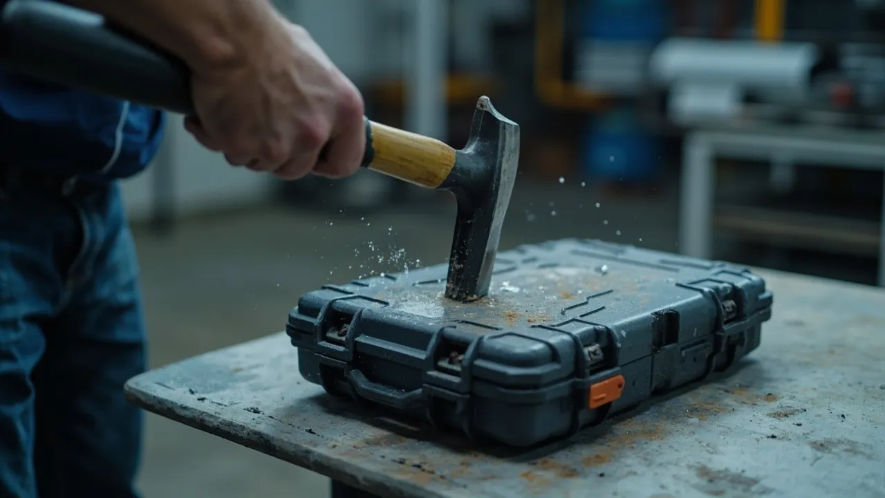
The short answer: an IK rating is the degree of protection an enclosure provides against external mechanical impact, defined by IEC 62262 and its Chinese equivalent GB/T 20138. It is expressed in joules of single-impact energy across eleven classes, from IK00 to IK10, and a higher number means the enclosure can absorb more impact energy. IK and IP are two entirely separate dimensions: IP governs the ingress of dust and water, while IK governs mechanical damage from impact. Protective cases are carried, loaded, stacked, thrown onto vehicles and bounced along rough roads, so the shell routinely experiences exactly the kind of low-energy, high-frequency impact that IK describes. To read IK properly you need three things working together: the energy-to-class conversion, the three standard impact apparatus (pendulum hammer, spring hammer and vertical drop hammer), and the mounting and strike-point rules that decide the result. This guide walks through each of them and ends with criteria you can paste straight into a technical agreement.
Many buyers and mechanical engineers see a figure such as IK08 for the first time and instinctively translate it into "how far can it be dropped." That is the single most common misunderstanding. An IK rating describes the ability of an enclosure to withstand a defined energy delivered as a single impact under controlled laboratory conditions without failing. It is a reproducible measured value, not a field verdict about whether a case survives a fall from a particular height. What actually happens in the field is the combined result of the IK class, the case geometry, material toughness, drop orientation, the mass of the contents and the cushioning design.
Contents
- What an IK rating actually is: definition and units
- IK versus IP: two independent ratings that work together
- From IK00 to IK10: the impact energy table
- Three standard apparatus: pendulum, spring and vertical drop hammer
- Test conditions: mounting, strike points and pass criteria
- Why protective cases must be rated for IK
- How IK relates to case structure and material
- IK testing is not the same as drop testing
- Choosing a class for different applications
- How to verify an IK claim in the supply chain
- Common misuses and traps
- A practical checklist for buyers and designers
- Frequently Asked Questions
- Conclusion and Related Reading
What an IK rating actually is: definition and units
IK is the international code for the mechanical impact protection component of enclosure protection marking. Its source standard is IEC 62262, Degrees of protection provided by enclosures for electrical equipment against external mechanical impacts (IK code), adopted domestically as GB/T 20138. The unit is unusually direct: impact energy expressed in joules. Energy equals mass times gravitational acceleration times drop height, or is set by the calibrated parameters of a pendulum or spring hammer. A higher class means more energy is delivered to the same specimen under the same conditions.
Three fundamental properties need to be stated up front:
- IK is an enclosure-level rating, not a system-level rating. The standard is concerned with whether the shell itself withstands a stated impact without damage that prevents continued use. It says nothing about whether the contents survive.
- IK is a single impact under defined conditions. It is not a fatigue life and not a cumulative damage figure after many drops.
- IK does not prescribe a material. Metal, engineering plastics and composites can all claim an IK class, provided they pass the corresponding test.
The definition of "damage" must be agreed in advance. The underlying intent of IEC 62262 is that the enclosure shall not show changes that impair normal use after the test. Applied to protective cases, this normally resolves into three criteria. First, structural integrity: no cracking, no penetration, no latch release, no hinge fracture. Second, functional retention: the case still opens and closes normally and the sealing function is not lost, retested against IP where required. Third, acceptable deformation: minor dents or scuffs that do not affect assembly or sealing are allowed, but the gasket land flatness and the seal groove must not be pushed out of tolerance by the impact. Writing all three into the technical agreement is the precondition for avoiding arguments about whether a sample is "actually broken."
IK versus IP: two independent ratings that work together
IP and IK are completely independent dimensions. Their source standards, their tests and their failure mechanisms all differ. Understanding the distinction is the key to using IEC 60529 and IEC 62262 correctly.
| Dimension | IP rating (IEC 60529 / GB/T 4208) | IK rating (IEC 62262 / GB/T 20138) |
|---|---|---|
| --- | --- | --- |
| What it protects against | Ingress of solid objects, dust and water | External mechanical impact |
| How it is written | IP plus two digits, for example IP67 | IK plus two digits, for example IK08 |
| Test mechanism | Dust chamber, water spray, immersion | Pendulum, spring hammer, vertical drop hammer |
| Typical failure | Dust ingress, water ingress, seal failure | Cracking, penetration, latch or hinge fracture |
| Can they be combined | Yes, IP67 and IK08 can both be declared | Yes, the two are mutually independent |
They influence each other but never substitute for each other. A case that reaches IP67 proves only that it keeps out dust and survives short immersion. It says nothing about impact resistance, and IK10 says nothing about water resistance. The relationship is subtler than simple independence: a strong enough impact can locally deform the gasket land and change the compression of the seal, destroying an IP67 rating that was previously valid. For a case that is both weatherproof and used to move high-value equipment, the correct approach is therefore to run the impact test first and retest the seal afterwards, verifying that the ingress protection rating still holds after impact.
For the full meaning of ingress protection, see how to read an IP67 rating. For the selection logic that connects IK with case choice, see IK impact rating and protective case selection.
From IK00 to IK10: the impact energy table

IEC 62262 and GB/T 20138 define eleven classes, with IK00 meaning no protection. The table below lists the nominal impact energy specified by the standard, which is the hard basis for judging a class and can be quoted directly.
| Class | Nominal impact energy (J) | Intuitive drop-energy analogue (for understanding only) |
|---|---|---|
| --- | --- | --- |
| IK00 | No protection | — |
| IK01 | 0.14 | Roughly a 150 g object falling 10 cm |
| IK02 | 0.20 | Roughly a 200 g object falling 10 cm |
| IK03 | 0.35 | Roughly a 350 g object falling 10 cm |
| IK04 | 0.50 | Roughly a 500 g object falling 10 cm |
| IK05 | 0.70 | Roughly a 700 g object falling 10 cm |
| IK06 | 1.00 | Roughly a 1 kg object falling 10 cm |
| IK07 | 2.00 | Roughly a 2 kg object falling 10 cm |
| IK08 | 5.00 | Roughly a 1.7 kg object falling 30 cm |
| IK09 | 10.00 | Roughly a 5 kg object falling 20 cm |
| IK10 | 20.00 | Roughly a 5 kg object falling 40 cm |
The drop analogues in the right-hand column are only there to build intuition. They are not an IK test method. IK testing has strict requirements for apparatus, energy calibration, strike points and mounting, and "hitting it with something heavy" is not evidence of any class. For the correct relationship between drop height and mass, see how to set drop test height for protective cases.
The energy steps between classes are not uniform. Moving from IK07 to IK08 more than doubles the energy, from 2 J to 5 J. IK08 to IK09 doubles it again, from 5 J to 10 J, and IK09 to IK10 doubles it once more. This means that going from IK08 to IK10 means withstanding four times the energy, which corresponds to a systematic upgrade of wall thickness, reinforcement ribs, corner radii, material toughness and even the way latches and hinges are fastened. It is not solved by "switching to a harder plastic."
Three standard apparatus: pendulum, spring and vertical drop hammer
IEC 62262 specifies three categories of impact apparatus. Which one is used depends on the size, shape, mounting and energy class of the enclosure. Understanding the boundaries of the three is what allows you to read "which method was used" out of a test report.
| Apparatus | Standard basis | Suitable specimen and energy range | Characteristics |
|---|---|---|---|
| --- | --- | --- | --- |
| Pendulum hammer | IEC 60068-2-75, test Eh (pendulum) | Small to medium enclosures, low to medium energy | Energy set by hammer mass and drop height, controlled direction |
| Spring hammer | IEC 60068-2-75, test Eh (spring hammer) | Handheld, field-serviceable enclosures | Portable, field-capable, repeatability depends on procedure |
| Vertical drop hammer | IEC 60068-2-75, test Eh (drop hammer) | Horizontal top faces, large panels | Free-falling mass strikes vertically, suits top-face evaluation |
The pendulum hammer is the most common method for electrical enclosures. The hammer is released from a defined height on a defined radius and strikes the specimen at its lowest point with calibrated energy. The spring hammer stores energy in a spring that is released to drive the head, which makes it portable, but the operator's technique affects the delivered energy, so a fixed strike point and a fixed release method are normally specified for a given specimen. The vertical drop hammer releases a defined mass from a defined height to strike a horizontal surface vertically, and is very well suited to evaluating a large flat area such as the top of a case lid.
Whichever apparatus is used, the report is only as complete as the elements it records. These are the apparatus type and calibration data, the energy at each strike point, the location and number of strike points, the mounting and support of the specimen, and the inspection items and conclusion after the test. A report that says "passed IK08" without stating the method and conditions is not reproducible in engineering terms.
Test conditions: mounting, strike points and pass criteria
The same case can produce substantially different results depending on how it is mounted. The standard imposes explicit requirements on mounting and strike points, and this is the source of many "it failed when we measured it" complaints.
Mounting. The specimen shall be mounted to represent its normal installation. Equipment that is fixed in service is mounted to its normal fixings on a rigid or standard fixture; portable equipment that sits freely is normally placed on a rigid surface or standard support, and must not be padded with soft material that absorbs energy. Running an impact test with the case sitting on foam significantly understates the impact severity of the real service condition, and the report is therefore misleading.
Strike points and repetitions. The standard requires impact to be applied, point by point, to the weakest and most exposed parts of the enclosure. These normally include the centre and corners of the top face, the middle of the side walls, the joint line where the lid meets the body, the walls adjacent to latches and hinges, the root of the handle, the area around the pressure equalisation valve, and any protruding feature. Each selected strike point receives the specified number of impacts — typically one per point, with some standards and customer specifications demanding more — and the strike points must be independent of one another.
Pass criteria and test sequence. The recommended sequence is: one, pre-test dimensional and visual inspection; two, apply impacts at each point; three, structural and visual inspection for cracking, penetration, latch release or hinge fracture; four, functional checks for opening, closing and handle load; five, where required, retest sealing or ingress protection. Writing step five into the agreement is what actually answers the engineering question of whether the case is still waterproof after being hit.
| Test element | Standard requirement (key points) | Practical implementation |
|---|---|---|
| --- | --- | --- |
| Mounting | Represent normal installation | Rigid support, no energy-absorbing padding |
| Strike points | Weakest and most exposed areas | Top face, side walls, joint line, beside latches and hinges, handle root |
| Impacts per point | Per standard or customer specification | One per point as standard, tightened for high-risk parts |
| Temperature pre-conditioning | Per product specification | Often added for low-temperature toughness |
| Pass criteria | No damage impairing use | Structure, function and protection assessed together |
Why protective cases must be rated for IK
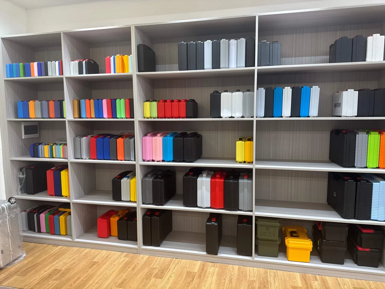
The real service history of a protective case is what makes IK matter more than many people expect.
- Manual handling and loading: airport baggage systems, parcel sorters and hand-throwing all generate repeated impacts.
- Stacking and crushing: during warehouse stacking, side walls take lateral impacts, and corners suffer most.
- Vehicle and equipment vibration with shock: off-road driving, construction machinery and mobile power applications bring continuous shock events.
- Field and rescue work: throwing, knocking and accidental strikes with tools.
- Military and law-enforcement use: rough handling during equipment transfer is unavoidable.
The common signature of these events is low to medium energy, high frequency, concentrated at corners and protruding features. IK testing reproduces this class of loading under controlled conditions in order to expose structural weak points. IK is therefore not a nice-to-have parameter but a leading indicator of case life and reliability. A case rated IK07 may come through baggage handling unharmed, while a case rated IK04 may show a deformed joint line and a failed seal after only a few flights.
How IK relates to case structure and material
Achieving an IK class is fundamentally a combination of three things: absorbing energy, spreading stress and locally reinforcing weak points. The factors below have the greatest influence in practice.
Material toughness matters more than hardness. Impact resistance depends on toughness, the ability to absorb energy before fracture, not on surface hardness. Polycarbonate offers excellent toughness and suits high-IK applications. Polypropylene is tough, chemically resistant and cost-effective, and is widely used for medium to high IK cases. ABS is stiff with excellent surface quality but has pronounced low-temperature brittleness, so using it alone in a high-IK application needs care. For the systematic differences between materials, see how to choose plastics for protective cases and PP, ABS and PC differences for cases.
Wall thickness and ribs determine resistance to deformation. Increasing wall thickness improves impact resistance up to a point, but thickening blindly brings sink marks, warping and extra weight. A more effective route is to place reinforcement ribs in load-bearing areas, since ribs substantially raise the second moment of area and deliver more stiffness with less material. For structural detail, see reinforcement rib design for cases and the relationship between wall thickness and strength.
Fillets and transitions are stress concentrators. Sharp corners have a high stress concentration factor and crack first under impact. Making the outer corners and rib roots into adequately large fillets — a typical rule is that the internal radius should be at least half the wall thickness, with the external radius matched — markedly improves impact resistance. For overall structural criteria, see how to design a high-strength case structure.
Latches, hinges and handles are the weak links. Impact rarely punches through the wall. It more often releases a latch, bends a hinge pin or cracks a handle root first. The fastening method for these parts — whether metal inserts are used, whether loads are spread, whether the local wall is thickened — is therefore decisive for IK performance.
| Design factor | How it affects IK | Practical rule |
|---|---|---|
| --- | --- | --- |
| Material toughness | Determines energy absorbed before fracture | Prefer PC or PP for high IK, use pure ABS with care |
| Wall thickness | Raises resistance to bending and denting | Balance against sink marks and weight, do not rely on thickness alone |
| Reinforcement ribs | Raise the second moment of area, spread load | Dense placement in loaded areas, large fillets at rib roots |
| Corner radius | Reduces stress concentration | Scale in proportion to wall thickness |
| Fastening of fittings | Prevents local tearing | Inserts, local thickening, spread the load |
| Low-temperature toughness | Plastics become brittle when cold | State the minimum service temperature and test cold impact |
IK testing is not the same as drop testing
This is the pair most often confused, and the distinction matters.
IK testing uses a calibrated impact apparatus delivering a defined energy to fixed strike points in a fixed direction, one point at a time, and evaluates the enclosure's degree of protection against mechanical impact. It answers the question of how much impact energy the shell can absorb.
Drop testing, as in ISTA, ISO 2248 and GB/T 4857.5, drops the whole packaged product from a defined height in a defined orientation, corner, edge or face, and evaluates the protective ability of the transport packaging system, including the case, the insert and the cushioning. It answers the question of how far the package can fall with the contents still intact.
| Dimension | IK impact test | Drop test |
|---|---|---|
| --- | --- | --- |
| Standard | IEC 62262 / GB/T 20138 | ISTA, ISO 2248, GB/T 4857.5 |
| Loading | Defined energy at single points | Free fall of the whole item from a defined height |
| Subject evaluated | Enclosure impact class | Overall protective ability of the packaging system |
| Result of interest | Whether the shell fails | Whether the contents are damaged |
| Typical use | Product class declaration for electrical and industrial enclosures | Transport packaging qualification |
They complement each other and cannot replace each other. An IK10 enclosure can still damage its contents in a 60 cm drop if the insert is poorly designed. Conversely, an IK06 enclosure with excellent cushioning can carry a whole case through a one metre drop. Transport qualification should use the ISTA and drop test methods, as covered in transport vibration testing for protective cases.
Choosing a class for different applications

The principle is to match the class to the service condition with a sensible margin, not to choose the highest class available, since higher classes mean more cost and more weight. The table gives empirical guidance; the customer specification and field data always take precedence.
| Application | Suggested IK class | Notes |
|---|---|---|
| --- | --- | --- |
| Indoor fixed installation, rarely moved | IK05 to IK06 | Normal level for electrical enclosures |
| General tool cases, workshop use | IK06 to IK07 | Balances cost and durability |
| Outdoor cases, field work | IK07 to IK08 | Corners and joint line need reinforcement |
| Air travel and repeated logistics | IK08 and above | Pair with drop testing for verification |
| Military, law enforcement and rescue transfer | IK09 to IK10 | Combine with MIL-STD-810 shock methods |
| High-value, hard-to-replace equipment | IK08 and above | Also verify sealing after impact |
Higher IK classes usually mean more weight and more cost. Choose by establishing what the worst realistic impact looks like, then stepping up one class for margin, rather than defaulting to IK10. For military shock methods, see what MIL-STD-810 test methods cover.
How to verify an IK claim in the supply chain
In B2B procurement, "the supplier claims IK08" and "there is evidence for IK08" are two very different things. Verify against the following list.
- Ask for the complete test report: standard number and revision, apparatus, energy class, strike point layout, specimen mounting method, before-and-after photographs and the conclusion.
- Check that the report matches the product: whether the model, material grade, wall thickness and latch configuration in the report match the production version, and whether a change triggers retesting.
- Separate prototype reports from production consistency: first-article or prototype success is not batch consistency, so agree on change-triggered retest rules.
- Watch for softened test conditions: padding the specimen, striking only the thickest areas, or skipping the joint line and the area beside the latches all inflate the result.
- Retest with a third party where warranted: for high-risk or large orders, commission an accredited laboratory to retest to IEC 62262.
JUNZHJIA is manufactured by KeXin New Materials (Guangdong) Co., Ltd. For OEM and ODM programs the company configures material, wall thickness, reinforcement ribs and latch and hinge solutions to the customer's service conditions, and supplies structural documentation, material data and test documents, so that IK class, strike point layout and post-impact seal retesting can be written into the technical agreement.
Common misuses and traps
Trap one: treating IK as a drop height. IK is an energy value, not a height. Converting between them requires mass and orientation, and the mechanisms differ.
Trap two: striking only the strongest areas. Photographing one thick region and declaring the class while avoiding the joint line, the area beside the latches and the handle root.
Trap three: padding the specimen. An energy-absorbing layer means the specimen receives far less impact than the standard demands, and the resulting "high IK" is meaningless.
Trap four: confusing enclosure IK with content protection. Passing IK does not mean the equipment inside is safe; cushioning and insert design is a separate line of work.
Trap five: ignoring low-temperature brittleness. Many plastics lose toughness sharply when cold, so a room-temperature IK08 does not mean IK08 at minus twenty degrees. Outdoor cases should have cold impact verification added.
Trap six: no retest after a change. Switching material, altering wall thickness or changing latch supplier can all change impact performance, and all belong on a change-triggered retest list.
A practical checklist for buyers and designers
For designers:
- State the target IK class and set out the worst-case impact assumption: energy, location and temperature.
- Prefer structure — ribs, fillets, thickness gradients — over simply changing material.
- Reinforce the joint line, the area beside the latches, the hinge seats and the handle root locally.
- Define the minimum service temperature and account for cold impact.
For buyers:
- Write the standard number and revision (IEC 62262 / GB/T 20138), the target class, the strike point layout, the test sequence and the pass criteria into the technical agreement.
- Require the complete test report and check it against the production version.
- Require post-impact retesting of sealing and ingress protection.
- Agree change-triggered retest rules and require written notice before any change.
For receiving inspection:
- Confirm structural and material consistency at first article approval.
- Sample-check critical structural dimensions such as wall thickness, ribs and fillets in production.
- Commission third-party retesting for high-risk orders.
Frequently Asked Questions
Q: Can a product carry only one of the two ratings, IP or IK? A: No, they cannot substitute for each other. IP governs dust and water ingress and IK governs mechanical impact. They are orthogonal dimensions with different standards, test methods and failure mechanisms. An IP67 case can absolutely crack from a single impact, and an IK10 case does not have to be waterproof at all. For outdoor protective cases that fear both water and impact, the right approach is to declare both ratings and to verify, using an impact-first-then-reseal sequence, that the ingress protection rating still holds after impact. The most common error in practice is testing IP but not IK. The product passes water testing perfectly in the laboratory, then a few knocks during loading deform the joint line and change the seal compression, and water enters in service. Buyers should specify both IP and IK targets in the technical agreement and state the test conditions and pass criteria for each.
Q: So exactly how far can an IK08 case be dropped? A: Strictly speaking, there is no unique conversion between IK and drop height, because IK is a defined-energy single-point impact while drop height belongs to free fall of a whole item. The two can be loosely related through the energy equation, energy equals mass times gravitational acceleration times drop height, so about five joules is roughly a 1.7 kg object falling 30 cm, or a 5 kg object falling 10 cm. But this is only an intuition aid. It is not a test method, and it does not let you conclude that an IK08 case will survive a 30 cm drop. The outcome of a real drop depends on orientation, geometry, material toughness and the mass distribution of the contents, and must be verified with the drop test methods in ISTA, ISO 2248 or GB/T 4857.5.
Q: Why do different laboratories produce different IK results for the same case? A: Four variables explain most of it. First, mounting and support: a specimen sitting on energy-absorbing material receives far less impact than the standard requires, so the result reads high. Second, strike point selection: striking only thick areas versus covering the joint line, the area beside the latches and the handle root can differ by one or two classes. Third, apparatus and calibration: the actual energy calibration and operating procedure of a pendulum, spring hammer or drop hammer all affect repeatability. Fourth, temperature pre-conditioning: plastics become brittle when cold and the result can drop noticeably. When judging an IK report, therefore, never look only at the class number. Look for the standard, apparatus, energy, strike point layout, mounting method, sequence and conclusion. A report missing these elements is not reproducible no matter how high the class.
Q: What does it take to reach IK09 or IK10 on a protective case? A: A system of structure and material working together, not any single measure. First, choose a tough material system; for high IK prefer polycarbonate or modified polypropylene, and be careful with pure ABS because of its low-temperature brittleness. Second, combine wall thickness with reinforcement ribs; thickening alone brings sink marks, warping and weight, while ribs deliver more stiffness with less material. Third, scale corner radii in proportion to wall thickness to reduce stress concentration. Fourth, reinforce and spread load at the real weak points: the joint line, beside the latches, the hinge seats and the handle root. Fifth, state the minimum service temperature and test cold impact. As a rule of thumb, moving from IK08 to IK10 means withstanding four times the energy, and that normally requires a systematic structural upgrade rather than a local tweak.
Q: Which performs better under IK, a plastic protective case or a metal one? A: It depends on the energy level, the temperature and the design, so there is no blanket answer. Metals such as die-cast aluminium and stainless steel are stiff and resist local denting, but they are heavy, costly, and can suffer permanent deformation under strong impact. Engineering plastics are tough, can rebound, are light and can be moulded into complex rib structures, which makes them advantageous in low to medium energy applications that also need low weight and corrosion resistance. The real difference is usually not which material is harder, but whether the structure spreads the load and reinforces the weak points. Comparing thin single panels of each material is meaningless. The correct comparison is a whole case tested to the same standard, energy class and strike point layout, with weight, cost, corrosion resistance and repairability assessed at the same time.
Q: Does an IK class have to hold at low temperature as well? A: That depends on the application and must be stated in the technical agreement. Many engineering plastics shift from ductile to brittle fracture when cold, so a case that passes IK08 at room temperature may perform noticeably worse at minus twenty degrees or lower. For outdoor use, cold chain, high-altitude or alpine work, and air transport where the hold is cold, add an impact test after low-temperature pre-conditioning, and specify the pre-conditioning temperature, the soak time and the test sequence. Without cold verification, declaring only a room-temperature IK class tends to produce exactly the dispute you want to avoid when brittle cracking appears in a cold environment. Writing the minimum service temperature and the cold impact requirement into the agreement is the cheapest available risk control.
Q: What exactly should be written into a technical agreement about an IK target? A: Six items cover it. First, the standard number and revision, for example IEC 62262 or GB/T 20138, to avoid differences between revisions. Second, the target class and its nominal impact energy. Third, the apparatus type — pendulum, spring hammer or vertical drop hammer — and its calibration data. Fourth, the strike point layout, covering the top face, side walls, joint line, beside latches and hinges, the handle root and around the vent valve, ideally with a diagram. Fifth, the mounting and support method, explicitly excluding energy-absorbing padding. Sixth, the test sequence and pass criteria, including visual, structural and functional inspection items and whether post-impact resealing or IP retesting is required. Add the change-triggered retest rules as well. With all six in place, the result is reproducible and can be used for arbitration.
Q: Why retest sealing after an impact test? A: Because the real failure mode of a protective case is usually that impact changes the geometry first, and water ingress follows. A strong enough impact can locally deform the joint line, warp the lid or push seal compression away from the design range, destroying a previously valid IP rating. If you run the impact test but never check the seal, you miss the most important failure chain. The technical agreement should therefore require that, after the impact test, ingress protection is retested to IEC 60529 and GB/T 4208 — at minimum the immersion or spray item — and that any water entry is recorded. For cases with a pressure equalisation valve, also confirm after impact that the valve still functions and is not jammed by debris. For the related structural and sealing detail, see the role of a pressure equalisation valve and how to choose case seal materials.
Q: How do you judge whether an IK test report is trustworthy? A: Look for completeness and internal consistency. A trustworthy report usually contains the standard number and revision, the test date and laboratory details, the specimen model, material and critical dimensions, the apparatus type and energy calibration, a strike point layout and count, a description or photograph of how the specimen was mounted and supported, temperature pre-conditioning conditions, before-and-after photographs, the structural and functional inspection results, and the final conclusion. Conversely, a report that says only "passed IK08" with no strike point diagram, no mounting description and no before-and-after photographs gives no way to judge its severity or to reproduce it. Also check whether the specimen configuration in the report matches the production version, and whether retest rules are agreed for material or structural changes. For high-risk orders, commission a third-party laboratory to retest against the same standard for comparison.
Conclusion and Related Reading
Back to the question in the title: an IK rating is the degree of protection against external mechanical impact defined by IEC 62262 and GB/T 20138, expressed in joules of single-impact energy across eleven classes from IK00 to IK10, and it neither replaces nor is replaced by an IP rating — the two work together. Reading IK well comes down to three things: the standard energy-to-class table, the three apparatus types and their suitable boundaries, and the three conditions that decide the outcome, namely mounting method, strike point layout and pass criteria.
Three actions you can take immediately. First, write IK and IP into the technical agreement together and specify an impact-first, reseal-second verification sequence, closing the most hidden failure chain, water ingress after impact. Second, define the strike points in detail — top face, side walls, joint line, beside latches and hinges, and the handle root — and ban energy-absorbing padding so the report cannot be inflated. Third, raise the class through structure rather than thickness or material alone — ribs, fillets, local reinforcement and low-temperature toughness are the real route from IK08 towards IK10.
JUNZHJIA is manufactured by KeXin New Materials (Guangdong) Co., Ltd. The product line covers protective cases, tool cases, military-spec storage cases and waterproof junction boxes, serving wholesale, distribution, OEM and ODM customers and global supply. The company configures material and structural solutions to customer service conditions and supplies structural documentation, material data and test documents.
Related Reading