

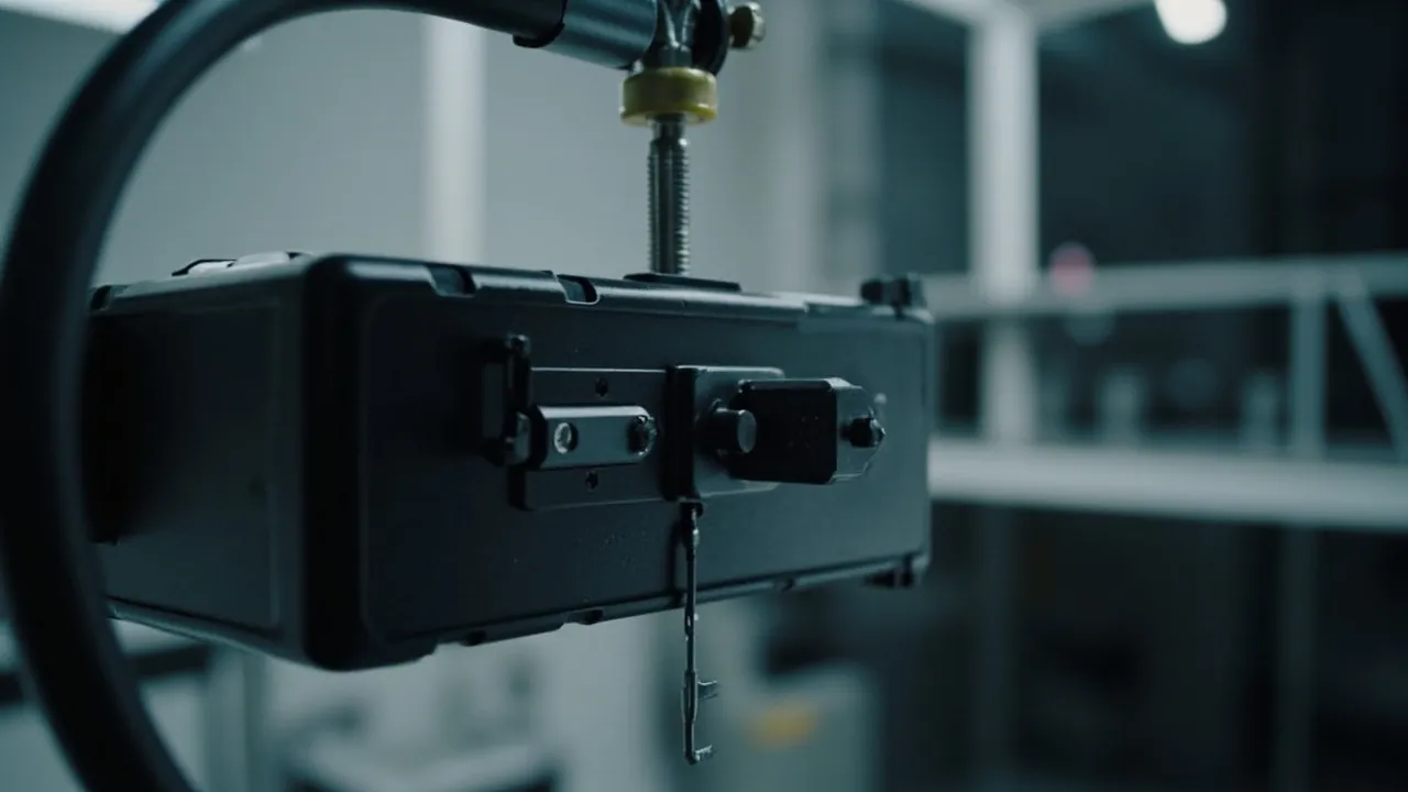
The short answer: a protective case latch does not have a single "how many times can it open" number. What it has is a decay curve — retention force plotted against cycle count. Industry figures such as 5,000, 10,000 or 30,000 cycles only mean something when the test temperature, opening angle, applied load, seal installation and failure criterion are all stated. The most common procurement mistake is copying a supplier's headline claim of "100,000 cycles" straight into a technical agreement without asking whether that figure came from an empty case, at room temperature, with no gasket fitted, judged only by "the latch did not break." Under realistic conditions — cold, fully loaded, with the gasket installed, judged by "retention force has not fallen below 30 percent of baseline" — the usable cycle count can be five to eight times lower.
This article translates latch life testing into engineering language you can act on. It first explains the three fatigue mechanisms that actually limit latch life, then describes how to build a repeatable cycle test rig, how to define the four test conditions, how to express pass/fail criteria as measurable numbers, which standards frameworks can be borrowed, how to read a retention decay curve, why a latch test without a gasket is almost worthless, how to approach accelerated life conversion, and finally how to write the whole thing into a purchase agreement. Every number quoted here is a typical or rule-of-thumb value. Real projects must be governed by the case drawing, the physical sample and an agreed test plan — none of these figures should be treated as an acceptance value by default.
Table of Contents
- The Bottom Line: Life Is a Decay Curve
- Why Latches Fatigue: Three Failure Mechanisms
- How to Build an Opening-Cycle Test Rig
- Defining Test Conditions: Temperature, Load, Speed, Angle
- Pass/Fail Criteria: Four Measurable Indicators
- Standards Frameworks You Can Reference
- Three Latch Architectures and Their Test Focus
- How to Read a Retention Decay Curve
- Why a Latch Test Must Include the Gasket
- From Bench to Field: Accelerated Life Conversion
- Common Failure Modes and Corrective Directions
- Writing the Clause and the Test Plan
- Frequently Asked Questions
- Conclusion and Further Reading
The Bottom Line: Life Is a Decay Curve
Plot opening force or retention force on the vertical axis and cycle count on the horizontal axis, and every latch draws the same shape: a flat opening stretch, a long gentle decline, then an accelerating collapse. The meaningful definition of life is the point where the curve crosses a threshold, not the point where the latch snaps. That point only means anything when three things are pinned down: how much decline counts as failure, under what environmental conditions the test ran, and how much load was inside the case.
Most figures circulating in the market describe the loosest possible criterion — "the latch body did not break and the case still closes." That criterion offers a buyer almost no protection, because a latch whose retention force has fallen by half will usually still close. It simply cannot compress the gasket any more, and the case then fails a water immersion or rain test outright. Any life requirement written into a technical agreement must therefore be a retention-ratio requirement, not a bare cycle count.
| Criterion Type | Typical Wording | Protection for the Buyer | Commonly Quoted Figure |
|---|---|---|---|
| --- | --- | --- | --- |
| Structural integrity | No fracture; still closes after cycling | Weak | 50,000–100,000 cycles |
| Operating force | Opening force within ±50% of baseline | Moderate | 20,000–50,000 cycles |
| Retention force | Retention not below 70% of baseline | Strong | 5,000–30,000 cycles |
| Seal linkage | Still passes the IP test after cycling | Strongest | 2,000–15,000 cycles |
This table is the clearest illustration of the problem: the same latch, judged by a different criterion, can be called good for twenty times longer. So when you see a life figure, the first question is the criterion, the second is the conditions, and only the third is the number itself.
Why Latches Fatigue: Three Failure Mechanisms
Latch failure is never a single cause. Three mechanisms compete, and whichever reaches its critical point first determines the life.
The first is material fatigue. Every opening cycle subjects the latch to one elastic deformation: the hook of a cam latch opens and springs back, the tab of a push-button latch bends and returns, the bail of an over-centre latch stretches and releases. Each cycle accumulates microscopic damage at stress concentrations — typically the root fillet, the base of the hook, or a weld line near the injection gate. When accumulated damage reaches a critical level, a crack initiates and propagates. This mechanism is highly temperature-sensitive: in cold conditions the polymer enters its brittle range and the same strain amplitude produces far more damage. That is the root cause of the sharp drop in cold-weather life, and the underlying mechanics are covered in the companion article on low-temperature brittleness testing.
The second is wear. Any latch whose parts slide against each other during opening generates debris at the contact faces. Once the cam face and slider wear, the over-centre position shifts. The symptom is a falling opening force and, eventually, a latch that pops open on its own. Wear rate depends on the material pair (polymer-on-polymer, polymer-on-metal and metal-on-metal behave very differently), surface finish and lubrication.
The third is loosening of fasteners and mounting points. The latch body may be perfectly intact while its mounting screws, rivets or snap seats work loose or crack under repeated load. The latch then shifts as a unit and retention falls. This failure usually appears first at the mounting bosses on the case wall — a structural problem rather than a latch problem.
Which mechanism dominates decides where you spend your money. If inspections show cracks dominating, address material and fillet radius first. If debris dominates, address contact materials and fit clearance. If mounting points loosen, add reinforcement ribs or change the fastening method.
How to Build an Opening-Cycle Test Rig
The whole point of a latch life rig is to perform the opening and closing action repeatably and in a quantifiable way. Complexity is not the goal; repeatability is.
A rig needs four subsystems:
- Drive. A servo motor with an eccentric cam or a crank-slider converts rotation into a reciprocating push-pull acting on the latch lever or the lid edge. Speed must be adjustable; 5–30 cycles per minute is the usual range.
- Force measurement. A load cell in series with the drive or at the latch lever records the peak force of every cycle, producing the opening-force-versus-cycle-count curve. That curve is the primary output of a life test.
- Counting and triggering. A photoelectric or proximity switch counts cycles and triggers a stop-and-inspect at preset intervals, for example every 500 or 1,000 cycles.
- Environment and load. Either the whole rig goes inside a thermal chamber for temperature cycling, or the case is filled with a specified ballast weight for loaded cycling. Doing both at once is impractical, so the standard approach is two rounds: a long room-temperature loaded run, plus a shorter thermal-cycling run.
One step that must never be skipped is the initial baseline measurement. Before cycling begins, measure retention force at a minimum of three positions (one per latch around the lid), initial opening force, and initial gasket compression or lid-to-rim gap. Without a baseline you cannot compute a decay rate, and the data reduces to the single bit of information "it did not break."
| Rig Subsystem | Key Parameter | Typical Value | Effect on Results |
|---|---|---|---|
| --- | --- | --- | --- |
| Drive | Cycle speed | 10–20 cycles/min | Too fast adds self-heating and overstates life |
| Force | Sampling rate | 100 Hz or higher | Too low misses peak opening force |
| Counting | Inspection interval | Every 500–1,000 cycles | Sets the resolution of the decay curve |
| Load | Internal ballast | 0%, 50%, 100% of rated load | Loading significantly shortens life |
| Angle | Opening angle | Full open (about 90°–180°) | Smaller angles inflate life; angle must be stated |
Defining Test Conditions: Temperature, Load, Speed, Angle
Test conditions determine whether two life figures can be compared at all. If the conditions are unstated, the numbers are uncomparable. Four dimensions must be defined.
Temperature. Cover at least three ranges: ambient (23 ± 2 °C), cold (-20 °C or -40 °C) and hot (+55 °C or +70 °C). Cold is the weak point for polymer latches; heat softens the polymer and accelerates creep, so retention also drops noticeably at high temperature. If the product ships to cold regions or high altitudes, the cold round is mandatory. The governing logic is discussed further in the article on high and low temperature testing.
Load. Three levels matter: empty (no ballast), rated load (filled to the nominal capacity) and overload (1.5 times rated). Empty-case testing yields optimistic life; overload testing is used to expose weak points rather than to produce a life figure. State in the technical agreement that the life figure applies at 100 percent of rated load.
Speed. Speed affects strain rate. Polymers are strain-rate sensitive: cycled fast, they behave stiffer and more brittle, so fast cycling tends to underestimate life. A rate of 10–20 cycles per minute approximates normal human handling.
Angle. "Full open" means the lid is opened to its maximum angle and then closed. If the test only cycles through 30 degrees, the latch deforms far less than in real use and the resulting life is badly overstated. The agreement must state the opening angle, or simply specify "full open to full closed."
Pass/Fail Criteria: Four Measurable Indicators
Criteria must be measurable, otherwise acceptance turns into an argument. Use all four of the following together.
Indicator one: retention-force retention ratio. With the latch closed, pull in the opening direction with a force gauge and record the peak force at which the latch releases. After cycling, a value of at least 70 percent of baseline (a rule-of-thumb threshold) is considered acceptable. This indicator links directly to gasket compression capability.
Indicator two: change in operating force. Record the maximum hand force needed to complete a normal open-close action. After cycling, it should stay within ±50 percent of baseline. A drop beyond 50 percent suggests the latch may release by itself; a rise beyond 50 percent suggests galling or deformation after wear, which degrades user experience.
Indicator three: appearance and structural integrity. No through cracks, no permanent deformation (defined as residual displacement above 1 mm after unloading), no loosened fasteners, no plastic bending of the hook. Crack inspection should be done at 5x magnification, because early root cracks are invisible to the naked eye.
Indicator four: seal linkage. After cycling, the case must still pass the agreed sealing test — at minimum an immersion test performed to the relevant IP rating conditions, or a quick pressure-decay check. This is the ultimate criterion and the one that best reflects real protective capability.
Use these four on an "all must pass" basis, not an "any one will do" basis. In practice, retention-force ratio is the first to fail, which is precisely what makes it valuable.
Standards Frameworks You Can Reference
Latch life testing falls under mechanical durability and fatigue. There is no international standard written specifically for protective case latches, so the working method is to borrow a general mechanical or environmental test framework and write a custom test plan on top of it.
Frameworks worth referencing include:
- ISO/IEC 17025 — the general requirements for the competence of testing and calibration laboratories. It determines whether the laboratory issuing a report is qualified at all, which is examined in detail in the guide to reading third-party test reports.
- GB/T 2828.1 — sampling procedures for inspection by attributes, used to fix the sample size and acceptance numbers for latch life sampling.
- MIL-STD-810H — Method 516 (shock) and Method 514 (vibration) are not latch cycle tests, but their philosophy of combining environment, load and repetition transfers directly; see MIL-STD-810H compliance.
- The ISTA series — transport test procedures whose vibration and drop stages indirectly challenge a latch's ability to stay closed in transit; see ISTA transport testing procedures.
- ISO 4180 and ASTM D6179 — test schedules for complete, filled transport packages and the standard test method for drop testing, both of which supply condition references for transport-scenario latch evaluation.
A key caution: because no dedicated standard exists, any claim of "meets standard X" for latch life should be read as "borrows part of standard X plus custom conditions." In that situation, writing the test plan into the technical agreement matters more than citing a standard number.
| Standard / Document | Purpose | Relation to Latch Life |
|---|---|---|
| --- | --- | --- |
| ISO/IEC 17025 | Laboratory competence | Determines whether a report is credible |
| GB/T 2828.1 | Sampling plan | Determines how many latches to test |
| MIL-STD-810H | Environmental test philosophy | Supplies combined temperature, vibration and shock logic |
| ISTA 1A / 2A / 3A | Transport testing | Indirectly challenges latch retention in transit |
| ISO 4180 | Transport package test schedule | Provides a complete-package evaluation framework |
| ASTM D6179 | Drop test method | Imposes shock loads on the latch during drops |
Three Latch Architectures and Their Test Focus
Cam latches. A cam passing over centre provides the lock-up, with a distinct snap at the end of travel. Their weak points are cam-face wear and fatigue at the base of the hook. Testing should track the over-centre peak force, because cam wear reduces it directly. These latches are sensitive to the preload designed in during latch selection: higher preload gives higher initial retention but also higher contact stress on the cam face and faster wear.
Push-button latches. A spring and tab provide the lock, released by pressing. Their weak points are spring fatigue and tab wear. Testing should additionally log button travel, which changes as the tab wears. In cold conditions these are a high-risk type because spring force rises while the polymer becomes brittle.
Over-centre bail latches. A flip-over metal or reinforced-polymer bail spans the lid and body. Their weak points are plastic elongation of the bail and wear at the pivot. Testing should measure bail length or residual tension when closed.
Different architectures shift the test focus, but all four criteria still apply. The mechanical division of labour between hinge, latch and gasket is covered systematically in matching hinge, latch and seal; latch life testing should never be treated in isolation from those two.
How to Read a Retention Decay Curve
Plot the retention force measured at each inspection point and three phases usually appear.
Phase one is running-in (roughly the first 500–1,000 cycles). Retention may dip slightly — typically 3 to 8 percent — as assembly stresses relieve and microscopic high points on mating surfaces flatten. This early decline is normal and should not be called a failure.
Phase two is the plateau. Retention stays essentially flat with minor fluctuations. The length of this phase determines the latch's useful life; most acceptable latches hold this plateau for tens of thousands of cycles. A longer plateau indicates better fatigue performance and better fit design.
Phase three is accelerated decay. Retention begins falling faster until it crosses the threshold. Once in this phase, the decline is effectively irreversible and accelerates. Engineering practice is to define end of life before the knee appears and to keep at least a 2x safety margin.
One useful trick when reading curves: overlay the cold-cycling curve on the room-temperature curve. If the two plateau slopes differ greatly, the material is temperature-sensitive and unsuited to high-frequency cold use; switch to a cold-tough material or add latches to share the load.
Why a Latch Test Must Include the Gasket
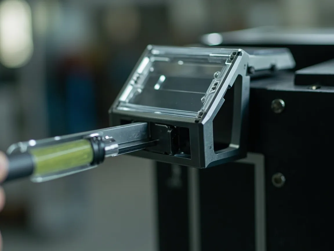
This is the single most important engineering recommendation in this article: latch life testing must be run with the gasket installed, and seal retention must be the final criterion.
The reason lies in what a latch is for. A latch does not seal anything itself. It pulls the lid toward the rim so that the gasket reaches its designed compression. The gasket — usually silicone or EPDM — accumulates compression set over time and cycles, while latch retention force decays. The two effects stack, so gasket compression falls steadily across the service life. Testing the latch body alone, without a gasket, omits the very link in the system that is most likely to fail first. Gasket material behaviour and compression-set characteristics are compared in detail in the article on case seal materials.
Practical points for testing with the gasket installed: use the production gasket, not a laboratory special; assemble at the compression ratio stated on the drawing; measure the lid-to-rim gap with feeler gauges, or measure gasket compression, at every inspection point; and at key points perform a quick sealing check, for example a pressure-decay airtightness test or an immersion test to IP conditions.
If results are unsatisfactory, the usual order of correction is: add latches first, then optimise gasket compression, and only then consider changing latch material. Adding latches is the most economical route because it dramatically lowers the load on each individual latch.
From Bench to Field: Accelerated Life Conversion
No laboratory can spend years proving real service life, so accelerated testing and conversion are necessary.
Three acceleration levers are common: raise the cycling frequency, raise the load, or raise the opening angle. All three increase the damage per cycle so that life is consumed in fewer cycles.
The underlying idea is damage equivalence, but it must be handled carefully. Polymer fatigue has temperature thresholds and strain-rate effects. Once a threshold is crossed, the failure mechanism can change from fatigue to brittle fracture, and results then cannot be scaled back to real conditions by simple proportion. Accelerated conversion is therefore valid only while the failure mechanism stays the same, and should be cross-checked with at least one milder acceleration step.
A practical three-step method: run a short baseline at real-world frequency (a few hundred cycles), run to failure at one accelerated level (say 2x load), then verify at an intermediate level. If the two accelerated levels convert back to similar baselines, the mechanism is consistent and the result can be trusted. If they diverge widely, the mechanism has changed and testing should return closer to realistic conditions.
Conversion must also account for time-dependent degradation. Gasket compression set, material ageing and corrosion of metal parts all degrade with calendar time rather than cycle count. Any converted cycle life must therefore be capped by a calendar limit as well — for example, "three years or 10,000 cycles, whichever comes first." This is the same family of mechanisms discussed in the article on UV ageing testing.
Common Failure Modes and Corrective Directions
Failure one: cracks at the base of the hook. Causes are usually a too-small fillet radius, an abrupt wall-thickness change, or a gate position that puts a weld line in the stress-concentration zone. Correct by enlarging the fillet, tapering the wall thickness, and moving the gate away from the loaded region.
Failure two: cam face worn flat, latch releases by itself. Causes are excessive contact stress, no lubrication, or insufficient wear resistance. Correct by increasing contact area, switching to a self-lubricating material such as molybdenum-disulphide-filled nylon, or adding a metal insert.
Failure three: mounting boss cracks or screw loosens. Causes are thin boss walls, no ribs, or no anti-loosening provision. Correct by adding reinforcement ribs, thickening the boss, or using anti-loosening screws or threaded inserts.
Failure four: one-shot brittle fracture in cold conditions. The polymer has entered its brittle range, so a single higher opening force is enough to crack it. Correct by selecting a material with better low-temperature toughness, such as impact-modified PP or a PC/ABS blend, and by revisiting polymer material selection.
Failure five: plastic elongation of the bail. The load has exceeded the material's yield strength. Correct by switching to a higher-strength metal bail or increasing the cross-section.
Writing the Clause and the Test Plan
When writing life requirements into a technical agreement, use the following structure and fill in every field so ambiguity is removed.
Clause one, structure and count. "The case is fitted with X latches, type/architecture XX, material XX."
Clause two, test conditions. "Life testing is run once at 23 ± 2 °C and once at -20 ± 2 °C; the case is loaded to 100 percent of rated capacity; cycle speed is 15 per minute; the opening angle is full open to full closed; production gaskets are installed."
Clause three, criteria. "Inspect every 1,000 cycles. At the end of cycling: retention force not below 70 percent of baseline; opening force within ±50 percent; no through cracks or permanent deformation; and the agreed sealing test passes."
Clause four, target and sample. "A minimum of XXXX cycles shall be achieved under cold conditions. Sample size per GB/T 2828.1, general inspection level II, acceptance numbers XX."
Clause five, reporting. "The supplier shall provide a test report including raw data (opening-force curve, retention inspection log, sealing test results). If testing is outsourced, the laboratory shall hold ISO/IEC 17025 accreditation."
Clause six, spares and maintainability. "Latches shall be replaceable parts. The supplier shall provide spares with an availability period of at least five years."
Written this way, latch life stops being marketing copy and becomes an inspectable engineering requirement. Configuring latch schemes for custom cases is one of the clearest indicators of an OEM factory's competence; evaluation methods are discussed in the article on case structure assessment.
Frequently Asked Questions
Q: What is a typical cycle life for a protective case latch?
A: There is no single number, because life depends heavily on criterion and conditions. Practical ranges: judged by structural integrity at room temperature with no load, an ordinary latch may reach 50,000 to 100,000 cycles; judged by opening force staying within ±50 percent, typically 20,000 to 50,000; judged by retention staying above 70 percent of baseline at rated load and room temperature, typically 5,000 to 30,000; and if cold conditions and the seal-linkage criterion are added, usable cycles often land between 2,000 and 15,000. The right question is therefore not "what is the life" but "at what conditions, by what criterion, and how many cycles." Buyers should first estimate true demand: five openings a day, five years, 250 working days a year is about 6,250 cycles; add a two-to-three-times margin and set a target of 15,000 to 20,000 cycles, then require the supplier to supply data at exactly those conditions.
Q: Why does latch life drop sharply in cold conditions?
A: Polymer mechanical behaviour is strongly temperature-dependent. As temperature falls, the material moves from its ductile range into its brittle range: elongation at break drops sharply and impact toughness collapses. That means for the same opening angle, the internal stress level is comparatively higher while the ability to absorb the same strain energy is lower, so microscopic damage accumulates much faster. Cold also hardens the material, raising opening force, so the latch carries a heavier load — a double penalty of higher load and lower toughness. As a rule of thumb, the same polypropylene latch taken from room temperature to -20 °C may lose one third to one half of its room-temperature cycle life; at -40 °C the loss is greater and the failure mode may change from fatigue cracking to a single brittle fracture. Any case intended for frequent use in cold regions or cold-chain logistics should therefore use impact-modified material and be tested for life at low temperature, rather than having its life extrapolated from room-temperature data.
Q: How many samples does a latch life test need?
A: Sample size depends on the confidence level and the decision you want to support. Two approaches are common. The first is development verification: three to five samples for exploratory testing, primarily to identify failure modes and the decay knee, with no statistical conclusion claimed. The second is acceptance sampling: use the attribute sampling plan of GB/T 2828.1 to determine sample size and acceptance numbers, for example at general inspection level II with an acceptable quality limit of 1.5 or 2.5. Note that latch life testing is destructive, so samples cannot be reused and quantities must be planned in advance. If the test cycle is very long, a sequential approach works well — inspect every 2,000 cycles and stop on the first failure — to control test cost while still reaching a conclusion. Reports should record an individual curve per sample rather than only an average, because averaging hides early failures of individual units.
Q: Does latch life testing have to be done by a third-party laboratory?
A: Not necessarily; it depends on the purpose. For internal development and process improvement, a factory rig is sufficient, provided the rig parameters are traceable, the data complete and the conditions documented. For public claims, customer acceptance, tenders or export compliance, a third-party laboratory holding ISO/IEC 17025 accreditation is advisable, because a report needs an accreditation backing it to be readily accepted. When commissioning a third party, confirm three details. First, whether the laboratory's accredited scope actually covers the test items you need — a mismatch between accredited scope and test item is a common problem. Second, who writes the test plan; it should normally be the client, not a generic laboratory template, otherwise conditions may diverge from real use. Third, whether the report includes raw data; a report stating only "pass" has little value for subsequent improvement. How to read a third-party report, and the difference between CNAS and CMA, is covered in the test report guide.
Q: How big is the difference between loaded and unloaded testing?
A: The difference can be large, and it always runs in the direction of shorter life under load. Internal contents transmit force through the case structure to the latch during opening: as the lid opens, the load can deform the case wall slightly and shift the latch's mounting position; as the lid closes, the load can affect rim contact. More importantly, a loaded case experiences higher overall loads during handling, stacking and transport, so the latch must not only maintain the seal but also resist the tendency of the lid to move relative to the body. As a rule of thumb, going from empty to 100 percent rated load typically shortens latch life by 30 to 60 percent. The technical agreement should therefore specify rated load as the test condition. If the product is routinely overloaded in service, run an additional 1.5x overload test, whose purpose is to expose structural weak points rather than to produce a life figure.
Q: Does adding more latches make each latch last longer?
A: Directionally yes, but there are limits. More latches reduce the reaction force each one carries and spread gasket compression more evenly around the rim, usually extending system life and improving sealing reliability. But three limits apply. First, cost and operating complexity: more latches mean more steps per opening, and users may only close some of them, producing local seal failure. Second, assembly consistency: more latches demand tighter compression consistency, and any single latch with excessive preload may fatigue first and become the system bottleneck. Third, diminishing returns: once the load per latch is already low, the life bottleneck shifts from the latch body to gasket compression set, and adding more latches no longer helps. Practical guidance: calculate the minimum number from rim perimeter and load, verify by life test, and if cold life is insufficient, add one more latch rather than switching to a more expensive material — the former is cheaper and takes effect faster.
Q: How do I know when a latch should be replaced?
A: A four-step field check works well. First, feel the closing action: if the latch closes but feels loose, or you must press the lid down to close it, retention has decayed or the structure has deformed. Second, do a simple retention check: with the latch closed, pull slowly in the opening direction; if the latch releases with far less force than a new case, replace it. Third, inspect visually for cracks, whitening, visible debris build-up or loosened fasteners at the hook base, cam face and mounting points. Fourth, verify sealing with a simple immersion or water-spray observation — if water traces appear inside, the latch-gasket system has already lost function. If any of the four steps is abnormal, replace the latches as a set and re-verify sealing rather than replacing just one, because latches from the same batch are usually at the same stage of degradation.
Q: What is a reasonable latch life requirement for a custom case?
A: The right method is to calculate demand first, then add margin, then tier by application — not to copy a high number. Step one, calculate demand: daily openings times years of service times working days per year. Step two, add margin: a two-to-three-times safety margin is generally considered reasonable. Step three, tier by scenario: long-term storage (under 0.1 openings per day) may need only a few hundred cycles, so an ordinary structure suffices; general industry (one to three per day over five years) needs about 1,250 to 3,750 cycles, which room-temperature criteria satisfy; high-frequency field use (five to ten per day) needs about 6,250 to 12,500 cycles, so a cold-condition retention criterion is advisable; extreme frequency (over 20 per day) exceeds 25,000 cycles, so optimise material, add latches and shorten the replacement interval simultaneously. One caution: more life is not automatically better. Raising from 20,000 cycles at room temperature to 20,000 at low temperature can raise cost substantially, and anything beyond genuine demand is waste.
Q: How does latch life testing relate to full-case transport testing?
A: They are complementary but not interchangeable. Latch life testing evaluates fatigue and wear from repeated opening — operational durability. Full-case transport testing, such as ISTA 1A, 2A, 3A or an ASTM D6179 drop, evaluates vibration, shock and stacking loads in transit — logistics durability. Real products experience both, so complete validation should include both. Transport testing especially exposes a different latch failure: under vibration a latch can creep slightly and gradually work loose, a mechanism entirely different from fatigue cracking, and only a retention check under vibration will reveal it. The recommended sequence is to lock in the structure with latch life testing, then verify the system with full-case transport testing, and finally check sealing on the post-transport sample — producing a complete evidence chain of operational durability, logistics durability and seal retention. Transport test methods are described in the article on ISTA and transport testing procedures.
Conclusion and Further Reading
Returning to the title question: latch cycle life testing is not really about how many times a latch opens; it is about how retention force decays with cycle count. Three steps turn this from vague into actionable. First, choose the criterion — retention not below 70 percent of baseline plus a passing sealing test is recommended as the core pair. Second, state the conditions — temperature, load, speed, angle and gasket installation, none of which can be omitted. Third, read the curve — identify running-in, plateau and accelerated decay, define end of life before the knee, and keep a two-to-three-times margin.
Three recommendations you can act on immediately. First, write "tested with gasket, at rated load, judged by retention-force ratio" into the technical agreement — those three phrases determine whether the life figure protects the buyer at all. Second, run the cold condition as a separate round, because polymer toughness is extremely temperature-sensitive and room-temperature data cannot be extrapolated. Third, run both life testing and transport testing — the former evaluates fatigue wear, the latter vibration loosening; the mechanisms differ and neither replaces the other.
JUNZHJIA, manufactured by KeXin New Materials (Guangdong) Co., Ltd., produces protective cases, tool boxes, military-spec storage cases and waterproof junction boxes for wholesale, distribution, OEM and ODM customers worldwide. The company supports test plan development for latch cycle life, loaded opening, cold-condition retention and seal linkage, supplies production gaskets and latch spares, and can provide either in-house test data or third-party laboratory reports on request.
Further Reading