

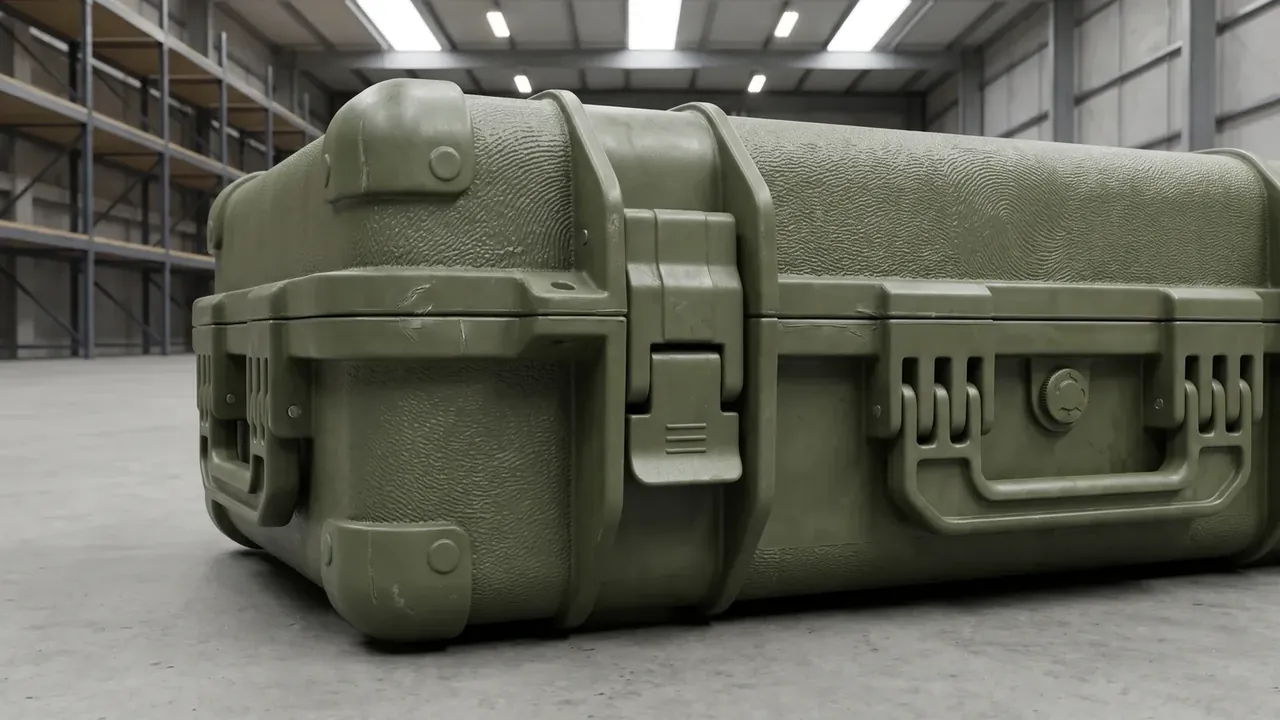
Quick answer: Military Radar Equipment Case hinges on long-edge bending: 1400 mm span, 22 kg load, 1.5 mm deflection limit set by six ribs and four corner supports.
Table of contents
- Why a Military Radar Equipment Case Starts With Long-Edge Stiffness
- Splitting 22 kg Across 3 Bays on a 1400 mm Envelope
- Six Ribs and Four Corner Guards Hold Deflection to 1.5 mm
- What a 1.0 m Drop Checks on Liner and Latches
- IP66, -30 °C to 60 °C and 2-Layer Stacking in Acceptance
- FAQ
1. Why a Military Radar Equipment Case Starts With Long-Edge Stiffness
Lay out the 1400 mm long side and the first problem a Military Radar Equipment Case solves is sag, not impact. With 22 kg inside, a short box sheds load through four walls, while a long side collects bending moment at midspan. Let the floor dip and the lid register drifts, putting the latches in a bind. On a 1400 x 480 x 360 mm envelope the order reverses: stiffness first, then cushioning.
The -30 °C to 60 °C range adds a constraint: the shell turns brittle when cold and creeps when hot. JUNZHIJIA conditions shells from one mould at both extremes before measuring midspan displacement, so the margin rests on more than one reading.
Outer size is 1400 x 480 x 360 mm, cavity 1330 x 410 x 300 mm, wall 5.0 mm, empty 12.6 kg, gross 34.6 kg at 22 kg load. Add 1 mm of wall and mass climbs without a stiffness gain; add 10 mm of cavity and the lid foam thins. A Military Radar Equipment Case spends material on six ribs, four corner guards and two handle seats, not thicker walls.
2. Splitting 22 kg Across 3 Bays on a 1400 mm Envelope
A long box suffers when all mass sits at midspan, so a Military Radar Equipment Case splits the 1330 mm cavity into 3 bays along the long side. Upright dividers and webbing hold each segment so 22 kg is carried as three loads, not one.
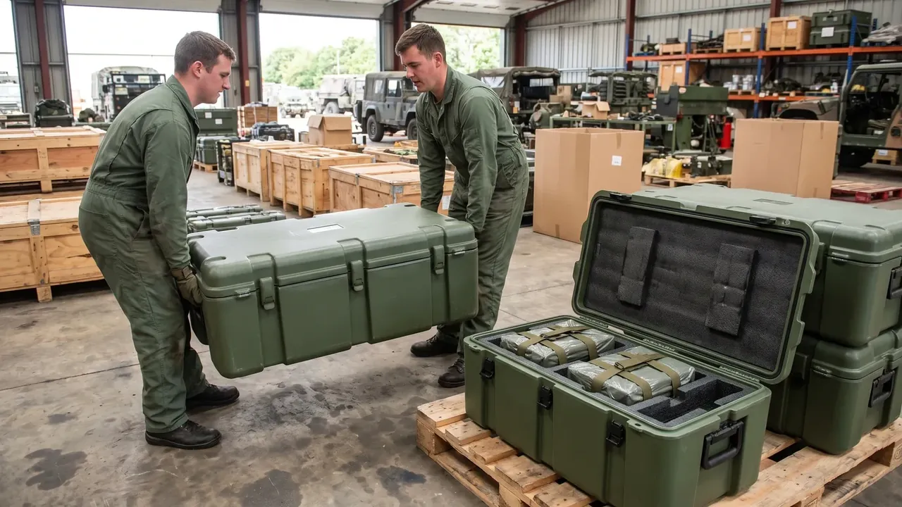
Bays redraw the floor load diagram: loads nearer the supports cut midspan moment. Table 1 lists the split, and the three figures add back to 22 kg.
| Bay | Cavity segment | Load allocation |
|---|---|---|
| Centre bay | middle 610 mm | 12 kg |
| End bay | one end 360 mm | 6 kg |
| Accessory bay | other end 360 mm | 4 kg |
With 2-layer stacking, 34.6 kg of an upper case passes through corner guards onto the lid below, so divider tolerance stays inside 1 mm. Bay walls are heat-bonded in one material to avoid a -30 °C shrink gap. A Military Radar Equipment Case shares one shell across all three bays, so one tall divider lifts the lid at midspan.
3. Six Ribs and Four Corner Guards Hold Deflection to 1.5 mm
Six longitudinal ribs run at equal pitch along the 1400 mm side with a T section above the 5.0 mm wall. The acceptance line is ≤1.5 mm deflection, read with the 34.6 kg case on two end supports and a dial at midspan. A Military Radar Equipment Case uses six ribs, not four, because a wider pitch lets the floor dish at midspan.
The four corner guards spread a drop point load into two neighbouring ribs, so no rib is overloaded. Table 2 sets load paths and limits on one shell.
| Load path | Reinforcement | Limit |
|---|---|---|
| Midspan floor | 6 longitudinal ribs | deflection ≤1.5 mm |
| Four corners | 4 corner guards | no cracking after 1.0 m drop |
| Lid rim | 4 latches | 520 N each, no release |
| End handle seats | 2 handles | 480 N each, no deformation |
Four latches at 520 N each and two handles at 480 N each are not arbitrary: at 34.6 kg carried by two people, each handle sees about 170 N static, and the threefold margin absorbs lift shocks. Guards and latches share stainless inserts placed before overmoulding, and a Military Radar Equipment Case draws hardware and ribs on one sheet so no drilling cuts a rib fibre.
4. What a 1.0 m Drop Checks on Liner and Latches
The 1.0 m drop is the closing criterion for this Military Radar Equipment Case, but a cracked shell is not the only review item. If lid foam debonds, the lid closes on a midspan gap; if one of four latches releases, the lid twists and stiffness is shed. The criterion is two lines: foam stays bonded, latches stay closed.
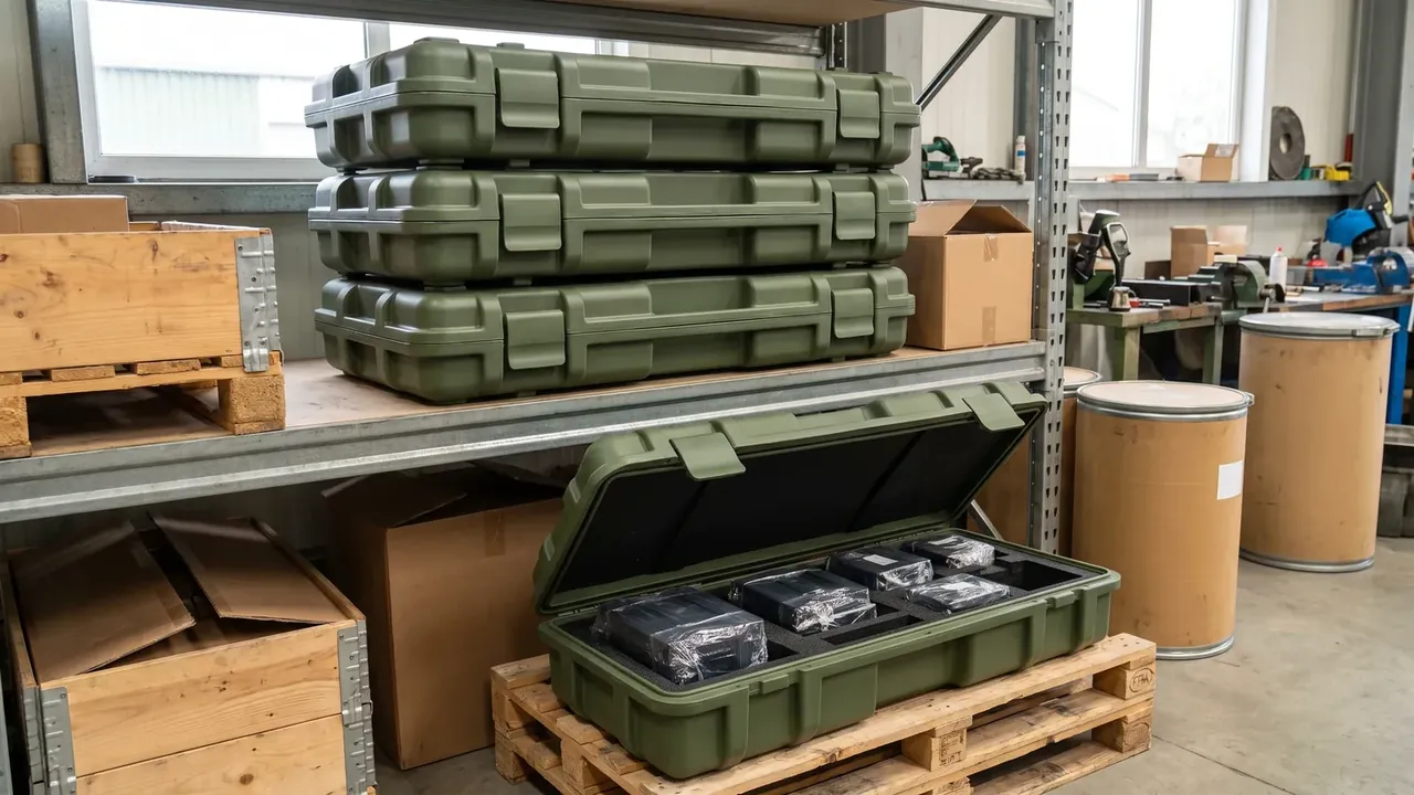
Testing is benchmarked to a drop method on the base, end face and one corner in turn, with midspan deflection and diagonal re-checked each pass. Bond strength is read on a peel specimen, number only. If deflection drifts from ≤1.5 mm to 1.8 mm, that Military Radar Equipment Case returns for a bond-line review.
5. IP66, -30 °C to 60 °C and 2-Layer Stacking in Acceptance
Table 3 puts three deflection values on one scale for the 22 kg static, 34.6 kg gross and post-drop readings.
| Deflection value | Measurement condition | Verdict |
|---|---|---|
| ≤1.5 mm | 34.6 kg gross, dial at midspan | release |
| 1.2 mm | 22 kg load, resting on two end supports | margin in hand |
| 1.8 mm | re-measured after 1.0 m drop | return for bond-line check |
Benchmarking sealing to IP66 reads gasket compression and the four latches together. 2-layer stacking keeps the lower lid loaded and a -30 °C to 60 °C swing overlays gasket recovery with floor creep, so cycling precedes the drop. A Military Radar Equipment Case re-measured at the 60 °C end must still fall inside ≤1.5 mm.
Passing still comes back to the midspan reading.
Conclusion
Splitting the 1400 x 480 x 360 mm long side into 3 bays and holding deflection to ≤1.5 mm with six ribs and four corner guards closes the design of this Military Radar Equipment Case. Bonded foam and four closed latches after a 1.0 m drop are the hardest lines. The -30 °C to 60 °C range, 2-layer stacking and 34.6 kg gross land on one acceptance table.
Related Reading
- Radar antenna case bays and lid foam
- Electronic equipment protective case selection guide
- Military communication equipment case structure
- Communication equipment case specification comparison
Related Products
- 8 Series — Gun Cases; Military Equipment Cases; Camera Equipment Cases; Drone Cases; Watch Cases; Knife Cases; First Aid Cases; Electronics Equipment Cases
- WL8-2812 PP Gun Case — model WL8-2812
- All protective cases and toolboxes: 7 series, 158 models