

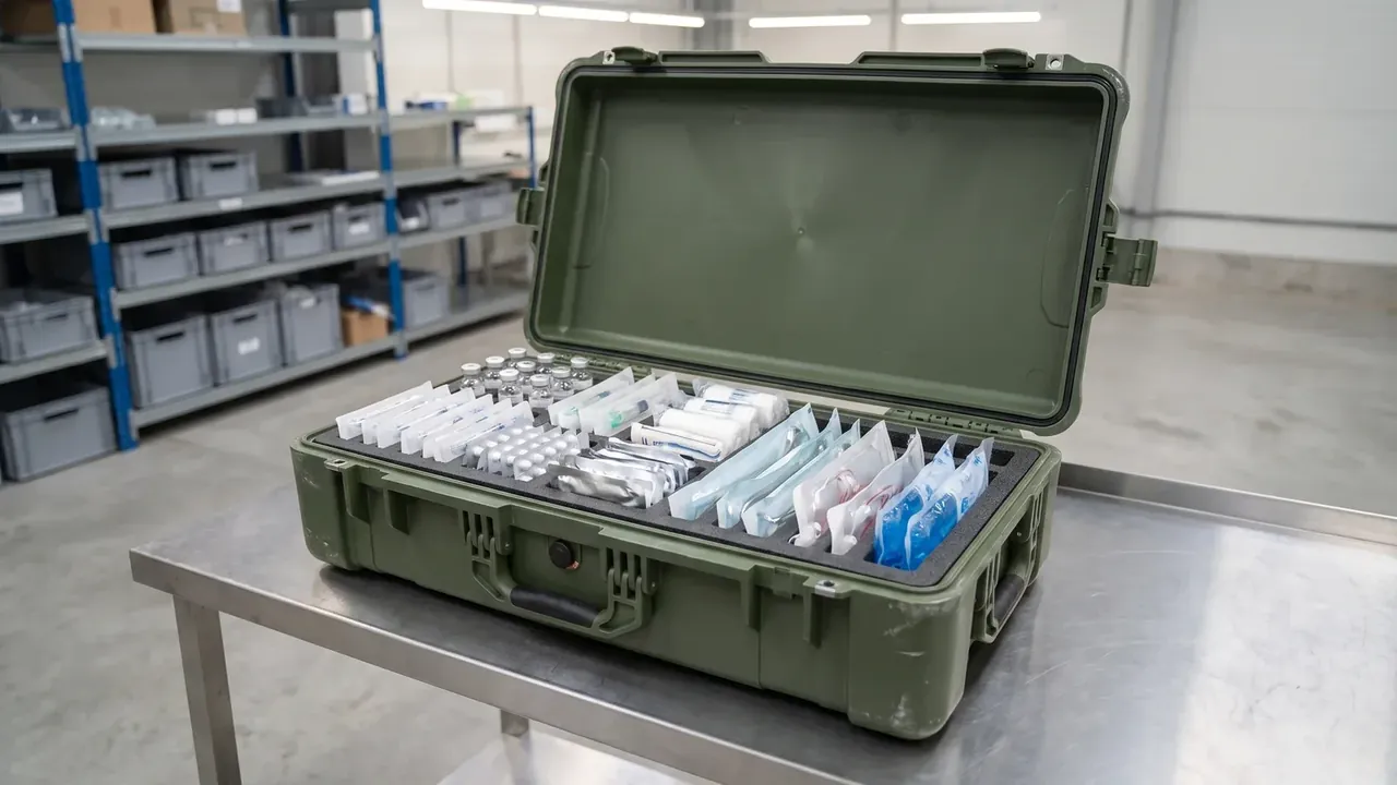
Quick answer: The Military Communication Equipment Case sets openings against sealing: 6 cut-outs of φ12 mm and 2 cable ports still have to hold IP67 at 1 m for 30 min.
Table of contents
- Three setup states and one opening conflict
- Carried: keeping one face closed
- Vehicle-mounted: four latches and four tiers
- Deployed: making up for six cut-outs
- Two cable ports and a 20 mm gasket
- FAQ
1. Three setup states and one opening conflict
The Military Communication Equipment Case works in three states that ask the wall for different things: no opening on the back when carried, corner straps and 4 tiers when mounted, panel holes and cable exits when deployed. The three meet on one shell of 580×420×260 mm, and the conflict condenses into one rule: every hole removes a stretch of seal.
The wall is 4.0 mm, the cavity 520×360×215 mm, the empty weight 7.1 kg. Half of that wall exists for the holes: 25 mm from a cut-out to the outer wall, 40 mm between holes, and after 6 holes of φ12 mm across a 520 mm face, what remains is the perimeter a gasket can press on.
| Setup state | Opening requirement | Sealing and shielding |
|---|---|---|
| Carried | No hole on the back face | Gasket continuous all round, never cut |
| Vehicle-mounted | 4 latches take the load | Straps run in external channels, not through the wall |
| Deployed | 6 panel holes of φ12 mm, 2 cable ports | Raised bosses, pressed bushes, clamped glands |
2. Carried: keeping one face closed
Carried, the Military Communication Equipment Case has one demand: no hole on the face that touches the back. A 7.1 kg empty shell wants its centre of gravity 30 mm below the mid line of the back plate, or it swings while the carrier walks.
A 4.0 mm wall across 520×360 mm bulges about 2.3 mm under 100 kg of side load; two ribs 8 mm high bring that to 0.9 mm, keeping the gasket at 25% compression.
Corners are weak points: a fold reaches only 70% of the straight-run compression, so each corner is drawn as an R12 arc.
3. Vehicle-mounted: four latches and four tiers
Vehicle-mounted, the Military Communication Equipment Case takes strap pressure and the weight above it. The 4 latches rate 450 N each, 1 800 N together, back-calculated from braking inertia with a 1.5 safety factor.
| Load point | Condition | Value |
|---|---|---|
| Strap channel | 0.8 g braking | 12 mm deep, bearing on the rib |
| Lid centre | 4 tiers stacked | Under 3 mm over 1.2 m |
| 4 latches | 1.2 m drop | 450 N each, 1 800 N total |
At 4 tiers the bottom lid carries 75 kg; past 3 mm of deflection the stack leans.
Straps on the Military Communication Equipment Case must not pass through the wall: two channels 12 mm deep keep webbing on a stiffening rib, not the sealing face. That is what pushes all panel holes onto the front and top faces.
4. Deployed: making up for six cut-outs
The 6 panel holes of φ12 mm are the heart of the conflict. IP67 means 1 m of water for 30 min, and every hole adds perimeter with no gasket over it: the six add about 226 mm of rim, close to 11% of the 2 000 mm outline.
The fix is to treat each hole as local structure. A boss 3 mm high is raised at the rim, a brass bush is pressed in flush, and anaerobic adhesive fills the gap between bush and bore. A 2 mm flat outside the boss gives the gasket a face, so each hole turns from a free edge into an enclosed ring.
Layout on the Military Communication Equipment Case follows the seal too: 2 rows of 3 holes, 40 mm apart on centres, the outer hole 35 mm from the wall edge, and a 60 mm solid band between rows so the gasket runs straight through.
The 120° lid angle comes from the deployed state: 180 mm of clear space between lid inner face and rim, while below 110° the lid edge presses on the top-row bush.
5. Two cable ports and a 20 mm gasket
In the Military Communication Equipment Case the 2 cable ports matter more for position than count. Both sit low on the rear wall, 45 mm above the base: higher and the cable drapes across the panel holes, lower and the port enters first on a wet floor. Each is a clamped gland with the collar compressed 30%.
The 20 mm conductive gasket is the compromise. Under 15 mm the contact area is too small to bridge a rim; over 25 mm the gasket covers the locating face of the boss and the bush cannot seat flat. At 20 mm the compression is 25%, 5 mm of squeeze, which recovers between −30 °C and 65 °C.
| Opening | Size | Sealing and shielding value |
|---|---|---|
| 6 panel holes | φ12 mm, 40 mm pitch | 3 mm boss, pressed bush, gasket bridging 20 mm |
| 2 cable ports | φ28 mm, 45 mm above base | Clamped gland, collar compressed 30% |
| Rim seal | About 2 000 mm perimeter | Gasket at 25% compression, R12 corners |
The three openings must be tested together. A leak test on the holes alone passes, and so does a soak test on the ports alone; only 6 holes, 2 ports and the full rim in 1 m of water for 30 min show whether the gasket collapses on the 40 mm strip between holes.
The 1.2 m drop is the second line. A boss is local thickening and therefore a stress riser, so its root carries an R2 fillet and the wall goes from 4.0 mm to 5.5 mm locally, with no whitening at any rim after the drop.
Conclusion
The difficulty in the Military Communication Equipment Case is not the wall but every opening cut through it. With 6 panel holes of φ12 mm, 2 cable ports and a full rim on one 580×420×260 mm shell, the answer is a set of values: boss, bush, 20 mm gasket, 25% compression. Put them on the drawing and the conflict becomes inspectable.
Related Reading
- Specification sheet for a military air transport case
- Choosing a military air transport case from the mission profile
- Compliance wording for military cases under the GJB system
- How to choose surface treatment for case hardware
Related Products
- 8 Series — Gun Cases; Military Equipment Cases; Camera Equipment Cases; Drone Cases; Watch Cases; Knife Cases; First Aid Cases; Electronics Equipment Cases
- WL8-2812 PP Gun Case — model WL8-2812
- All protective cases and toolboxes: 7 series, 158 models