

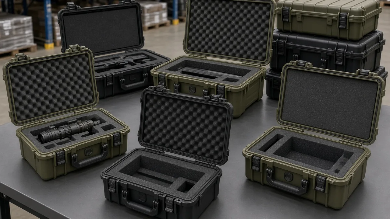
An electronic equipment case looks much like an ordinary instrument case, a shell with a liner inside. Once the contents include printed circuit boards, connectors, sensors, or semiconductor devices, the packing logic changes completely. Circuit boards fear two things. The first is vibration and shock during transport cracking solder joints, component leads, and connector pins. The second is electrostatic discharge, commonly shortened to ESD, where charge accumulated on a person or a packaging material punches through a thin gate oxide in a few milliseconds and destroys the device. One problem is mechanical and the other is electrical, yet both must be solved inside a single case, and their solutions sometimes interfere. This article addresses container-side vibration and static protection design only, and does not cover internal circuits or component selection.
Taken apart, the design of an electronic equipment case follows two parallel lines. The mechanical line establishes the fragility and resonant frequency of the equipment, selects a vibration isolation approach, and arranges retention and cushioning so that transport vibration and handling drops do not reach the devices. The electrical line establishes the sensitivity class, selects dissipative liner materials, and builds a controlled bleed path so static charge drains away safely before a device is touched. The two lines meet on the same liner layer, because that liner must both absorb vibration and behave as a semi-conductive element. Understanding this is understanding the fundamental split between an electronic equipment case and a general protective case. A sensible manufacturer asks for three inputs before starting: equipment weight and center of gravity, the location of the most vulnerable components, and the packing and unpacking procedure.
Why the Two Design Lines Work Against Each Other
Vibration isolation and static protection each have mature tools, but they push liner material requirements in opposite directions. Isolation favors material that is soft, compressible, and able to absorb energy through deformation, because softer material extends the impact duration and lowers peak acceleration. Static dissipation favors a material with a stable conductive network that holds surface resistance within a band that is neither too high nor too low. Most soft foams are excellent insulators with extremely high surface resistance, so accumulated charge has nowhere to go, while highly conductive materials tend to be stiff with limited resilience and therefore poor at isolation. This is the central difficulty of electronic case liner design: no single material is naturally optimal at both ends.
The engineering answer is layering, so the cushioning layer and the dissipative layer each do their own job and are then combined structurally. A common arrangement puts a thin dissipative layer against the equipment for static bleed and surface protection, a cushioning foam beneath it to absorb energy, and the shell structure below that. The critical part of this arrangement is the interface. If an air gap or a discontinuous adhesive layer exists between the dissipative layer and the cushioning layer, the bleed path breaks and the dissipative layer becomes an isolated electrode. A second easily overlooked issue is accumulated thickness: every added layer consumes volume, so the stack must enter the dimensional chain calculation early rather than being discovered after the liner is finished and the contents no longer fit.
Fragility and Resonance: Translating Equipment Dynamics into Material Parameters
Isolation design begins with fragility, the maximum acceleration the equipment tolerates. Fragility is not a fixed material property; it varies with structure, component mounting, and load direction. The same circuit board is usually weaker perpendicular to its plane than within it, so isolation design must respect directionality rather than relying on a single blanket number. Fragility is normally measured by drop or vibration testing, and experience values from similar equipment can serve as a starting point, but in either case the weakest mounting configuration should be the basis for verification.
Resonance is equally important. Every elastic system has a natural frequency, and when external excitation approaches it, the response is amplified by an amount that depends on damping. The risk for an electronic case is that the shell, liner, and equipment together form a system whose natural frequency coincides with an energetic region of the transport spectrum, magnifying modest input into something capable of destroying components. Design should therefore estimate the first natural frequency and keep it away from the energetic bands of the transport profile. Increasing stiffness or adding damping both shift the natural frequency and the amplification, but the two have different effects on isolation, so they must be balanced against equipment fragility. General methods for avoiding resonance and assessing fatigue appear in the transport resonance analysis.
Isolation Approaches: Mounts, Foam Cushioning, Suspended Liners
Three approaches dominate practice, suited to different weight and precision ranges. Rubber or elastomeric mounts serve heavier equipment and modular installations. Their stiffness and damping can be tuned through formulation and geometry, and their load capacity is stable, but low-frequency isolation is limited and rubber hardens over time. Foam cushioning absorbs energy through crush and recovery and suits small and medium equipment with low cost and easy forming, though compression set and declining resilience accumulate with age and drive a replacement interval.
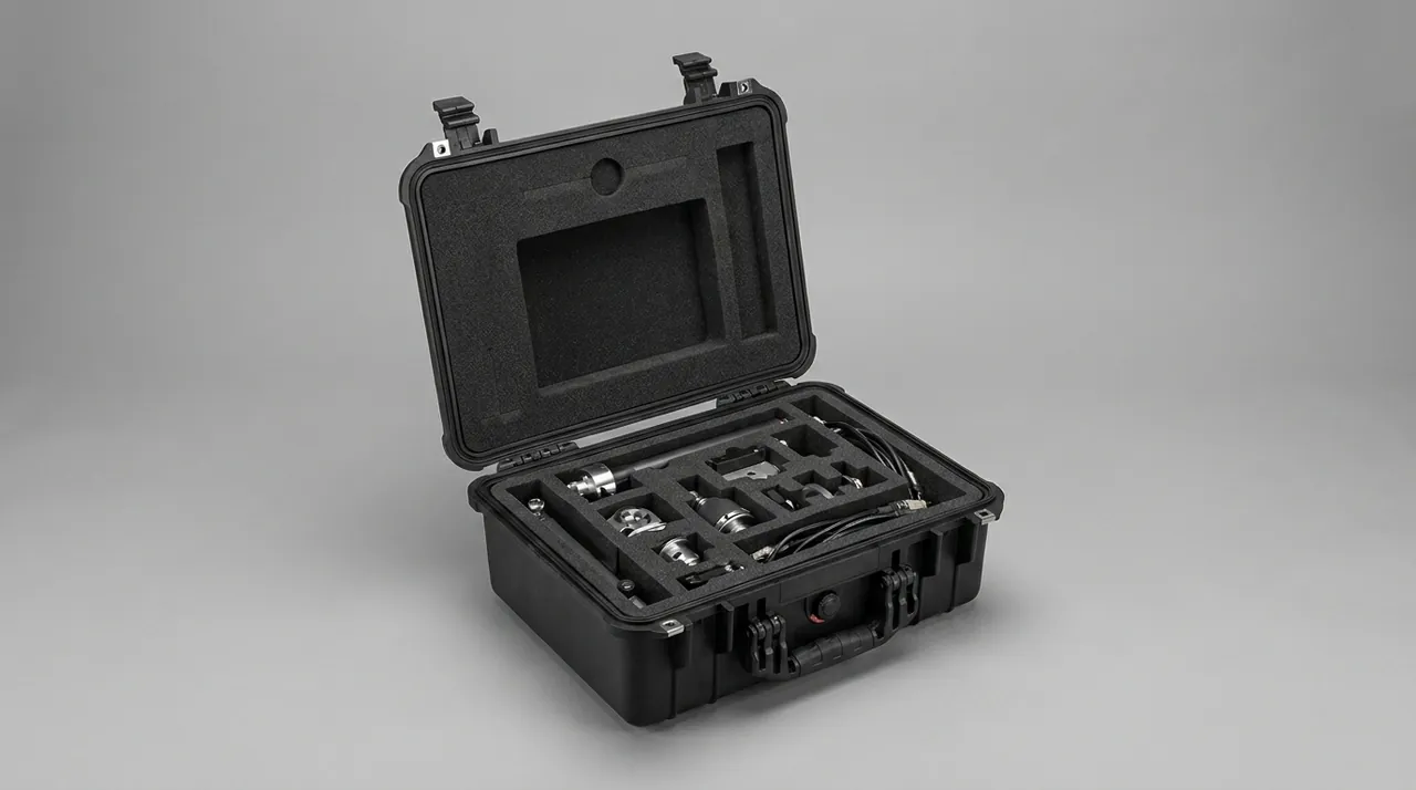
The third approach suspends the liner inside the shell using elastic connectors, giving the equipment a controlled displacement stroke relative to the shell. Suspension offers a long absorption stroke that flattens acceleration peaks and suits very fragile equipment, at the cost of space, complexity, and expense, with fatigue life entering the maintenance plan. The selection logic is short: fragility sets the stroke, weight sets the stiffness, and opening frequency sets the material. Lower fragility demands a longer stroke, heavier equipment demands greater support stiffness, and frequent opening calls for materials with slow resilience decay. Turning those three rules into concrete parameters is how a design avoids the familiar outcome of a case that feels soft and still breaks its contents.
Transport Vibration and Resonance Amplification
The most direct way to verify isolation is vibration testing. Practice usually begins with a sine sweep to locate the system's resonant frequency and amplification, followed by fixed-frequency or random vibration against a transport profile. The sweep matters because it exposes the natural frequency: as excitation sweeps past it, an accelerometer on the equipment records a response clearly above the input, and the ratio between them is the amplification factor. Excessive amplification means insufficient damping, and the response is to adjust foam density, thickness, or add damping structure.
Avoiding a dangerous frequency can follow two routes. The first moves the natural frequency by raising system stiffness or adding mass so the frequency lands in a low-energy region of the transport spectrum. The second increases damping to reduce the height of the resonance peak without changing its location, using foams with better damping, multiple layers of different densities, or dedicated damping adhesive layers. Practice usually combines them, shifting first and then flattening the peak. One caution applies to both: sweep and random vibration should be performed on the packed configuration, including liner, restraints, and a closed lid, because the assembly method changes the system dynamics significantly. Where equipment is extremely sensitive, an aggravated spectrum should be cross-checked against measured transport data so that test conditions do not become so gentle that they lose the power to discriminate.
Three Resistance Zones: Conductive, Dissipative, Insulative
The engineering language of static protection is surface resistance. By order of magnitude, materials fall into three zones. Conductors have very low resistance and drain charge instantly, but the discharge can produce a large instantaneous current that is itself a risk to some devices. Dissipative materials sit in a middle band and drain charge at a controlled rate, neither accumulating it nor producing a large current, which makes them the ideal zone. Insulators have extremely high resistance, so charge that accumulates stays on the surface until contact with a conductor triggers a sudden discharge. Static protection design therefore constrains every material touching a device to the dissipative zone while preserving a path to ground.
Two common misconceptions deserve correction. The first is that metal is inherently antistatic. Metal is indeed conductive, but if an insulating liner separates it from the equipment, charge can still accumulate near the device; conversely, metal touching component leads directly produces a fast discharge when charged. The second misconception is that lower resistance is always better. Static protection seeks controlled bleed rather than the fastest bleed, and excessively low resistance brings high discharge current and short-circuit risk. The correct wording in a specification is therefore dissipative liner rather than conductive liner, paired with a stated target band for surface or volume resistance and the test method used. Technical requirements for static-safe enclosures appear in the ESD case technical requirements.
Volume-Conductive Versus Surface-Coated Liners
Two technical routes produce a dissipative liner, and they differ in where the conductive network sits. Volume-conductive material disperses conductive filler such as carbon black, carbon fiber, or metal powder through the base resin so the whole thickness carries a conductive network. Its advantage is durability, since the conductive function does not disappear when the surface wears, which suits high-wear, frequently accessed applications. The drawback is that filler changes mechanical behavior, usually stiffening the foam and reducing resilience, which weakens isolation. Surface coating applies a conductive layer onto ordinary foam or sheet, delivering dissipative behavior while preserving the softness of the base material, at lower cost with better isolation. Its weakness is limited wear resistance, so repeated abrasion creates local loss of conductivity and a break in the bleed path.
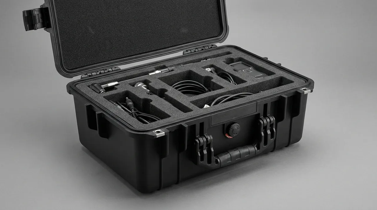
Which route fits depends on the relative weight of wear and isolation. Where access is frequent, contents heavy, and contact friction high, volume-conductive material is preferable, accepting the loss of softness and making it up through structural layering. Where handling is gentle and cushioning dominates, surface-coated material works, provided the wear specification and replacement interval are stated. A middle route laminates a thin volume-conductive sheet as the contact surface onto soft cushioning foam, combining conductive durability with isolation performance at the cost of process complexity. Whichever route is chosen, the material specification should state both conductive and mechanical parameters, so that nobody optimizes resistance while overlooking that the material has become a hard board.
Grounding and Equipotential Bonding at the Liner Level
A dissipative material drains charge only if it is connected to ground. In an electronic case that path usually has three segments: the dissipative layer, the conductive connection between liner and shell, and the grounding interface on the shell. If any segment breaks, static accumulates on the liner surface and discharges when a device is removed. For this reason, how a liner is installed often influences static protection more than the resistance of the material itself. An excellent dissipative foam lying loosely in a plastic case has essentially no useful function.
Several established methods produce a dependable connection. A conductive backing on the liner can be bonded or pressed onto a conductive area of the shell. A conductive jumper such as braided strap or conductive foam can bridge shell and liner, with torque and inspection interval stated in the assembly document. A conductive shell lets the liner contact the wall directly. Whichever method is used, the inspection document should define the resistance limit and measurement location between liner and shell, because this is a classic case where assembly quality determines protection. Where devices must be bonded to the liner as well, a dedicated equipotential terminal lets the operator establish equal potential before handling. Component-level requirements appear in the ESD component protection reference.
Humidity Control: Desiccant, Indicators, and Sealing
Humidity and static are entangled variables. In a dry environment surface resistance rises and charge accumulates more easily; in a humid one static risk falls, but corrosion, mold on optical parts, and degraded insulation become concerns. An electronic case therefore cannot simply pursue the driest possible interior, and should instead hold internal humidity within a band set by equipment requirements. Three container-level measures apply: raise sealing performance to limit moisture ingress, place desiccant inside to absorb residual moisture, and provide humidity indication so users know when replacement is due.
Desiccant management is frequently neglected. Its capacity is finite, and once saturated it stops working; without an indicator, users assume the presence of desiccant means nothing further is required. A practical remedy is a humidity indicator card or reusable indicator with a readable window on the lid or an inspection port, so the interior state can be judged without opening the case. For long-term storage, a replaceable desiccant cartridge packages the absorbent in a unit that can be swapped individually, avoiding a full open every time. Sealing again raises the pressure question: a well-sealed case develops a differential across temperature and altitude changes that can deform the gasket, so whether to fit a vent valve must be decided together with the humidity target, since the valve itself becomes a moisture path.
Meeting Shielding and Static Dissipation Together
Some electronic equipment needs both static dissipation and a degree of electromagnetic shielding, which complicates the liner further. Shielding requires a continuous conductive network forming a closed conductive surface, while dissipation requires resistance that is not too low, and the target bands differ. More awkward still, connecting a dissipative material to the shell creates a conductive path that may itself behave as an antenna, coupling external interference into the case or radiating internal noise outward. Meeting both requirements therefore calls for splitting the liner into two layers: the layer touching the devices stays dissipative, and shielding is handled by a separate conductive layer or shell coating, clearly separated by structure.
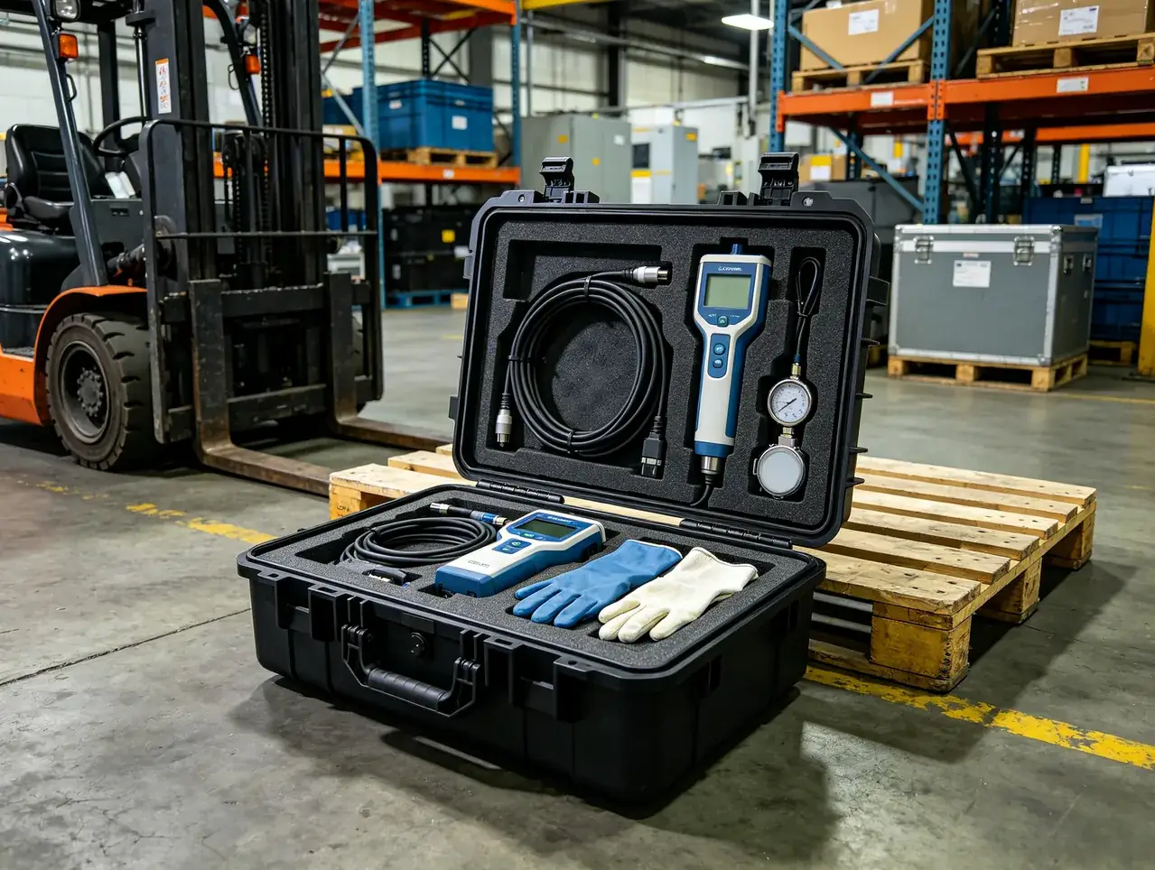
A further benefit is serviceability, since the dissipative layer is a consumable that can be replaced alone while the shielding layer, usually on the shell side, lasts much longer. One caution applies to the connection between the two: bonding at multiple points can create a ground loop, so a single point or a defined set of points is safer, and the arrangement should be explicit on the drawing. Where equipment has strict electromagnetic compatibility requirements, container shielding and dissipation are one part of the overall protection scheme and should be coordinated with the equipment's own filtering, grounding, and shielding. Combined approaches are discussed in the EMI shielded case reference and the anti-static component tray case guide.
Packing and Handling Practices: How the Case Supports Procedure
Even a well-designed case depends on procedure to deliver its protection. Most static accidents happen during handling: a person walks across a dry floor, opens the lid, and touches a device directly, and the accumulated charge discharges through the device. Container design should therefore make correct practice easier rather than harder. Useful features include a grounding terminal reachable from inside the lid, so an operator can touch it first to establish equal potential; a wrist strap hook or dedicated interface so grounding straps have a defined home; and a removable liner tray so a user can carry devices to a workbench rather than fishing inside the case.
The case must also leave room for antistatic packaging to work alongside it. Devices normally travel inside antistatic bags, conductive foam, or blister packs as a first level of protection, with the liner acting as the second level, and neither replaces the other. Liner dimensions must therefore include the thickness of that primary packaging rather than being cut to bare device sizes, which is among the most common dimensional errors in electronic case design. Handling procedure should also state the sequence clearly, establishing equal potential first, opening second, and removing devices last, with the sequence marked on the case so that correct practice becomes part of the container. General electronics container practice appears in the electronics box reference.
Inspection and Acceptance: Resistance Testing and Vibration Re-test
Acceptance for an electronic case covers two families of tests. The electrical family centers on surface or volume resistance measurement, which requires attention to three points. Electrode geometry and applied voltage must match the standard method used, since readings from different methods cannot be compared directly. Ambient humidity strongly affects results, so testing should occur at the specified humidity with the condition recorded. Multiple locations should be measured, including the most worn areas and points near seams, because a single passing reading does not qualify the whole case. Beyond resistance, the connection resistance between liner and shell should be verified, since it determines whether the bleed path exists at all. Cases with shielding requirements also need effectiveness re-testing across the agreed band.
The mechanical family centers on vibration and shock re-testing. Acceptance should run sweep and random vibration on the packed configuration, record acceleration response at key locations, and check that amplification stays within tolerance; for fragile equipment, an equivalent drop test should follow with inspection of devices and connectors afterward. Notably, surface and connection resistance should be measured again after testing, because vibration can change the contact between liner and shell and abrade conductive coatings. Putting post-test re-measurement into the acceptance plan covers degradation risk in both the mechanical and electrical domains at once. For military or export programs, the applicable standard and method should follow local regulations, export control requirements, and the customer's designated standard, and container-level testing demonstrates container performance only, not equipment certification.
Common Failure Modes and Procurement Pitfalls
Electronic case failures cluster in a few places. The first is loss of dissipative capability, where a coated surface wears through or a volume-conductive material develops a break in its network at a fold, raising local resistance and letting charge accumulate. Wear-resistant materials, protective layers at contact surfaces, and a scheduled liner inspection and replacement plan address it. The second is an interrupted bleed path, where the liner-to-shell connector loosens or conductive adhesive ages and the dissipative layer becomes an isolated electrode. Inspectable, replaceable connections with stated torque and inspection intervals prevent it. The third is isolation failure, where excessive compression set exhausts the cushioning stroke and vibration reaches the equipment directly, which a replacement interval tied to material density prevents.
Procurement mistakes reduce to four. The first is treating antistatic as a label rather than a parameter set, so no surface resistance figure, test method, or humidity condition is requested and the material's real performance cannot be judged. The second is comparing liner price while ignoring mechanical performance, which buys a material that passes on resistance but is as stiff as a board and therefore useless for isolation. The third is ignoring primary packaging dimensions, so liners are cut to bare device sizes and cannot accommodate antistatic bags and blister packs, forcing on-site foam trimming that destroys any guarantee of protection. The fourth is testing material coupons instead of the packed configuration, so sweep data looks good while the resonance point shifts once assembled and protection fails in practice. Writing these four points into the technical specification and acceptance plan sharply reduces rework. Comparable practice for military electronics containers appears in the military electronics case guide, the ESD case technical requirements, and the EMI shielded case reference.
Closing Perspective: Keeping Mechanics and Electronics in Their Places
Electronic equipment case design is genuinely difficult because one case must resolve two sets of physical problems whose liner requirements point in opposite directions. The answer remains layered function with disciplined interfaces: a cushioning layer absorbs energy, a dissipative layer controls charge, a shielding layer isolates interference, connectors route dissipation to ground, and the shell provides mechanical foundation and sealing. Each layer's parameters must be stated precisely enough to be tested and accepted, or the design intent never reaches production. For buyers, sharing equipment fragility, static sensitivity, packing procedure, and maintenance resources with the supplier lets the container serve both mechanical and electrical needs from the start, which is the only way to avoid a case that is impressively rugged while its contents still fail. Related component handling containers are described in the anti-static component tray case guide.
Frequently Asked Questions
Q: Why can an electronic equipment case not simply be a general protective case with foam added? A: Because a general protective case only handles environmental isolation and impact cushioning, while electronic equipment carries an additional risk of electrostatic discharge, and the two liner requirements point in opposite directions. A general case wants material that is soft, resilient, and able to absorb energy, and most soft foams are excellent insulators with extremely high surface resistance, so accumulated charge has nowhere to go. Electronic equipment requires the contact surface to sit in the dissipative zone so charge drains at a controlled rate. Using ordinary foam directly around a circuit board may cushion well, yet the risk of destroying a device during handling rises sharply, especially in dry seasons and on synthetic flooring. An electronic case also needs room for primary antistatic packaging, so liners cannot be cut to bare device dimensions, and the dissipative layer must maintain a dependable connection to the shell. Where shielding is also required, another conductive layer enters the stack. The sound approach is to redesign the liner around actual fragility and static sensitivity rather than swapping foam into an ordinary shell.
Q: Is lower surface resistance always better? A: No. Static protection seeks controlled bleed rather than the fastest possible bleed. By order of magnitude, materials divide into conductors, dissipative materials, and insulators. Conductors drain charge instantly, but the discharge can produce a large peak current that is itself a risk to devices with extremely thin gate oxides. Insulators hold charge on the surface for a long time and release it suddenly on contact with a conductor, which is the most direct hazard. Dissipative materials occupy the middle band and drain charge at a controlled rate, avoiding both accumulation and excessive current, which makes them the right zone for an electronic case liner. A specification should therefore say dissipative liner and state the target band for surface or volume resistance together with the test method. Buyers should also ask which standard method, electrode geometry, and applied voltage the supplier used, plus the humidity at which testing occurred, because humidity shifts readings substantially, and the same material can differ by several orders of magnitude between dry and damp conditions.
Q: How are vibration isolation and static protection reconciled in liner materials? A: Mainly by layering, so that each material carries only one function. A common three-layer structure places a thin dissipative material against the equipment for static bleed and surface protection, cushioning foam beneath it to absorb vibration and shock energy, and shell structure and restraints below that. After layering, softness and conductivity no longer have to be satisfied by one material, which widens the selection space considerably. The cost is more complex interface management, since the conductive path between the dissipative layer and the shell must stay continuous or the dissipative layer becomes an isolated electrode that actually accumulates charge more readily. A second cost is accumulated thickness, because each layer consumes interior volume and must enter the dimensional chain early. A middle route laminates a thin volume-conductive sheet with soft foam to balance conductive durability against isolation performance, at the price of process complexity. Whichever structure is chosen, combined vibration and resistance verification should be performed on the packed configuration rather than on materials alone.
Q: How should vibration testing be conducted so that it actually means something? A: The key is to test the packed configuration rather than material coupons or an empty case. Packed means the liner, restraints, primary antistatic packaging, and a closed lid are all in place, because the assembly method changes the natural frequency and damping of the system significantly. Testing normally proceeds in two stages. A sine sweep first locates the first natural frequency and amplification factor, revealing whether a dangerous frequency falls within an energetic region of the transport spectrum. Random vibration or fixed-frequency testing against a transport profile then confirms the condition of devices and connectors under sustained excitation. Acceptance should record acceleration response curves at key locations, verify that amplification stays within tolerance, and re-measure surface resistance and liner-to-shell connection resistance after testing, because vibration can alter contact and abrade conductive coatings. Fragile equipment also warrants an equivalent drop test. Putting all of these into the acceptance plan covers mechanical and electrical degradation risk in a single pass.
Q: Why does the grounding connection between liner and shell matter so much? A: Because a dissipative material drains charge only when it is connected to ground, and that path usually has three segments: the dissipative layer, the conductive connection between liner and shell, and the grounding interface on the shell. If any segment breaks, static accumulates on the liner surface. This explains why the same material performs so differently under different assembly methods. An excellent dissipative foam lying loosely inside a plastic case has almost no useful function, while the same material bonded or pressed to a conductive area of the shell drains charge reliably. Three methods are common: a conductive backing pressed onto conductive shell areas, a replaceable conductive jumper between shell and liner, and a conductive shell that the liner contacts directly. Whichever is used, the inspection document should define the resistance limit and measurement location between liner and shell, and specify connector torque and inspection intervals, treating this step as a key control point for assembly quality rather than a detail.
Q: How should humidity inside an electronic equipment case be controlled? A: Humidity and static are entangled, so the goal is not the driest possible interior but a band set by equipment requirements. A dry environment raises surface resistance and makes charge accumulate more easily, while a humid one lowers static risk but increases corrosion, mold growth on optical parts, and degraded insulation. The container can do three things: raise sealing performance to limit moisture ingress, place desiccant inside to absorb residual moisture, and provide humidity indication so users know the interior state. Desiccant management is the most neglected part, because capacity is finite and a saturated cartridge stops working; without an indicator, users assume the presence of desiccant means nothing more is needed. A practical remedy is a humidity indicator card or reusable indicator behind a readable window, so the state can be judged without opening the case. For long-term storage, a replaceable cartridge design lets the absorbent be swapped individually instead of opening the whole case each time.
Q: What special treatment does the liner need when shielding is also required? A: Dissipation and shielding must be split into two layers with a clearly defined structural separation. Shielding needs a continuous conductive network forming a closed conductive surface, while dissipation requires resistance that is not too low, and the two target bands differ; forcing one material to serve both usually satisfies neither. A further concern is that a conductive path may itself behave as an antenna, coupling external interference inward or radiating internal noise outward, so the number and location of connections between the layers must be controlled to avoid ground loops from multiple bonding points. The usual division of labor keeps the layer touching devices dissipative and assigns shielding to a separate conductive layer or a shell coating. This also improves serviceability, since the dissipative layer is a consumable that can be replaced alone without disturbing the shielding layer, which typically sits on the shell side and lasts much longer. Where equipment has strict electromagnetic compatibility requirements, container shielding and dissipation are one part of the overall scheme and should be coordinated with the equipment's own filtering and grounding.
Q: What are the most common mistakes when purchasing an electronic equipment case? A: Four stand out. The first is treating antistatic as a label rather than a set of parameters, requesting no surface resistance figure, test method, or humidity condition, so material performance cannot be judged and evaluation after delivery becomes guesswork. The second is comparing liner unit price while ignoring mechanical properties, which buys a material that passes on resistance but is as stiff as a board, effectively surrendering isolation and making damage during transport more likely. The third is ignoring primary packaging dimensions, cutting liner cavities to bare device sizes so that antistatic bags and blister packs no longer fit, forcing on-site foam trimming that leaves neither protection nor appearance intact. The fourth is testing coupons rather than the packed configuration, producing attractive sweep data while the resonance point shifts after assembly and protection fails in service. All four can be avoided by writing requirements into the technical specification and acceptance plan: define the resistance band and test method, specify both conductive and mechanical parameters, design liners around primary packaging, and re-test vibration and resistance on the packed configuration.