

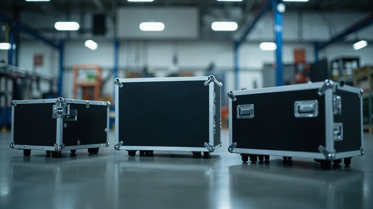
In electronics manufacturing, repair, and transport, many high-value components are not destroyed by being dropped. They are quietly damaged by invisible electrostatic discharge (ESD) or electromagnetic interference (EMI). The conclusion is direct: an anti-static box is responsible for safely dissipating static charge and preventing discharge breakdown, while an EMI-shielded case blocks external electromagnetic radiation to keep sensitive circuits working normally; together they form a complete ESD/EMC protection plan. This article is written for electronics procurement, quality, and repair engineers. It systematically explains the principles, standards, structure, and selection of anti-static boxes and EMI-shielded cases, and shows how to use them together with electronic component boxes and PCB transit cases and electronic device carry cases.
Static and electromagnetic problems are especially prominent in component transport, field repair, and outdoor operations. A qualified protection plan must consider material conductivity, grounding path, seam shielding, and mechanical cushioning at the same time, rather than solving only a single dimension. A useful rule of thumb is to treat the box as a small "controlled environment": inside it, charge should be guided, fields should be blocked, and shocks should be absorbed, all without any one of the three defeating the others.
Table of Contents
- What Are Anti-Static Boxes and EMI-Shielded Cases
- Harm Mechanism of Electrostatic Discharge (ESD)
- ESD Protection Grades and Standards
- EMI-Shielded Cases and EMC Basics
- Shielding Effectiveness and Shielding Materials
- Structural Design of Anti-Static Boxes
- Seam and Interface Treatment of EMI-Shielded Cases
- Typical Application Scenarios
- Synergy with Cushioning Liners
- Synergy with Waterproof Sealing
- Selection Parameter Checklist
- JUNZHJIA Anti-Static and Shielding Custom Capability
- Common Application Mistakes
- FAQ
- Conclusion and Related Reading
What Are Anti-Static Boxes and EMI-Shielded Cases
An anti-static box is a case made of static-dissipative or conductive material that can safely release static charge and prevent internal components from discharge breakdown. It usually lines the interior with conductive foam or anti-static EVA and provides a grounding terminal or conductive fastener, placing the components inside in an equipotential, low-potential-difference safe environment. An EMI-shielded case is a box covered with a highly conductive material (metallized coating, conductive composite plastic, or metal liner) that has high attenuation capability against external electromagnetic fields, protecting sensitive circuits from interference or preventing its own radiation from leaking out.
The two focus on different problems: the anti-static box solves "charge accumulation causes discharge," while the EMI-shielded case solves "electromagnetic coupling causes malfunction." In precision electronics transport they are often combined — for example, paired with the rigid shell of a plastic protective box, with anti-static liner and metallized shielding layer inside, achieving mechanical, electrostatic, and electromagnetic triple protection. It is important to note that neither replaces the other: a box can be perfectly anti-static yet transparent to radio waves, or fully shielded yet able to zap a board through a careless touch, so both properties must be specified and tested independently.
Harm Mechanism of Electrostatic Discharge (ESD)
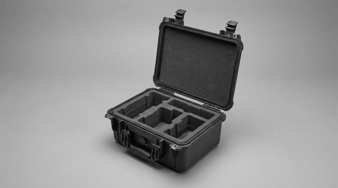
ESD harm comes from potential difference. When a person or equipment carrying static charge approaches a component, if the gap breakdown voltage is exceeded, the instantaneous discharge current can reach several amperes with a nanosecond rise time, enough to burn a MOS gate oxide or cause a latent defect that makes the component fail prematurely later. For CMOS, IGBT, RF front-end, and similar devices, a discharge of just tens of volts can cause irreversible damage.
The core idea of protection is "equipotential + slow dissipation." Keep all components, liner, and shell inside the box on the same low-resistance path, so static charge is evenly dissipated at the moment of contact rather than discharging concentrated at one point. This is consistent with the design goal of an anti-static component box, except the protective box emphasizes the enclosure and convenience of transport and carry scenarios. The "latent damage" aspect is often underestimated: a device may pass final test after a small ESD event and still degrade, so the failure shows up months later in the field, far from the original handling step, which makes root-cause analysis difficult and raises warranty cost.
ESD Protection Grades and Standards
Common international standards for measuring ESD protection include ANSI/ESD S20.20, the IEC 61340 series, and the widely referenced ESD STM5.1 (Human Body Model, HBM) in the electronics industry. Protective box materials are usually divided by surface resistance: conductive (<10^4 Ω), static dissipative (10^4–10^11 Ω), and insulative (>10^11 Ω). Transport boxes mostly fall in the static-dissipative zone, which dissipates charge without generating sparks from overly fast discharge.
| Metric | Conductive | Static Dissipative | Insulative |
|---|---|---|---|
| --- | --- | --- | --- |
| Surface Resistance (Ω) | <1×10^4 | 1×10^4–1×10^11 | >1×10^11 |
| Typical Use | Grounded liner | Box liner | Not for protection |
| Risk | Too fast discharge | Recommended | Charge accumulation |
Experience value: the liner surface resistance of a transport protective box is recommended to be controlled between 10^6 and 10^9 Ω, balancing dissipation speed and safety, and paired with a grounding fastener to form a complete dissipation path.
Beyond surface resistance, the charge-decay time and the tribo-electric behavior of the liner material also matter: a liner that generates charge when rubbed by the component during transport can defeat its own dissipative rating. Therefore the liner should be a low-tribocharge material, and acceptance should include a charge-decay test, not only a point resistance reading. For medical and automotive grades, refer to the relevant IEC 61340 clauses and keep the material certificate with the batch record.
EMI-Shielded Cases and EMC Basics
EMC (electromagnetic compatibility) has two aspects: EMS (immunity, equipment is not disturbed by external interference) and EMI (emission, equipment does not disturb the outside). The EMI-shielded case mainly serves EMS, attenuating the external electromagnetic field through a highly conductive continuous covering layer before it enters the internal space. Shielding effectiveness SE is expressed in decibels (dB); the larger the value, the stronger the attenuation.
Many scenarios need shielding: high-precision instruments in the field multimeter protective case series, medical detection modules, and communication receiving front-ends can all misread or be damaged in strong electromagnetic environments. The shielding case and the internal circuit ground design must be planned together, otherwise seams and cables become leakage channels. In practice, a shielded box is only as good as its weakest opening: a 60 dB wall is worthless if a cable gland or unfiltered connector lets the field straight through, so the connector treatment is part of the specification, not an afterthought.
Shielding Effectiveness and Shielding Materials
Shielding effectiveness depends on material conductivity, wall thickness, and frequency. Low-frequency magnetic fields are hard to shield (requiring high-permeability material), while high-frequency electric fields are easy to shield (a conductive layer suffices). Common solutions include metallized plastic (vacuum nickel/copper plating), conductive paint, stainless steel/aluminum liner, and conductive composite engineering plastic.
| Material Solution | High-Freq Electric | Low-Freq Magnetic | Weight | Cost |
|---|---|---|---|---|
| --- | --- | --- | --- | --- |
| Metallized coating plastic | Excellent | Medium | Light | Medium |
| Conductive paint | Good | Medium | Light | Low |
| Aluminum/steel liner | Excellent | Good | Heavy | High |
| Conductive composite plastic | Excellent | Medium | Light | Medium-High |
For scenarios that also need low-temperature protective boxes, confirm that the coating does not crack at low temperature and that adhesion does not drop. Selection should also consider repairability: a sprayed coating that chips at a corner reopens a leakage path, whereas a bonded metal liner tolerates more abuse, so the field environment should decide the construction rather than the catalog default.
Structural Design of Anti-Static Boxes
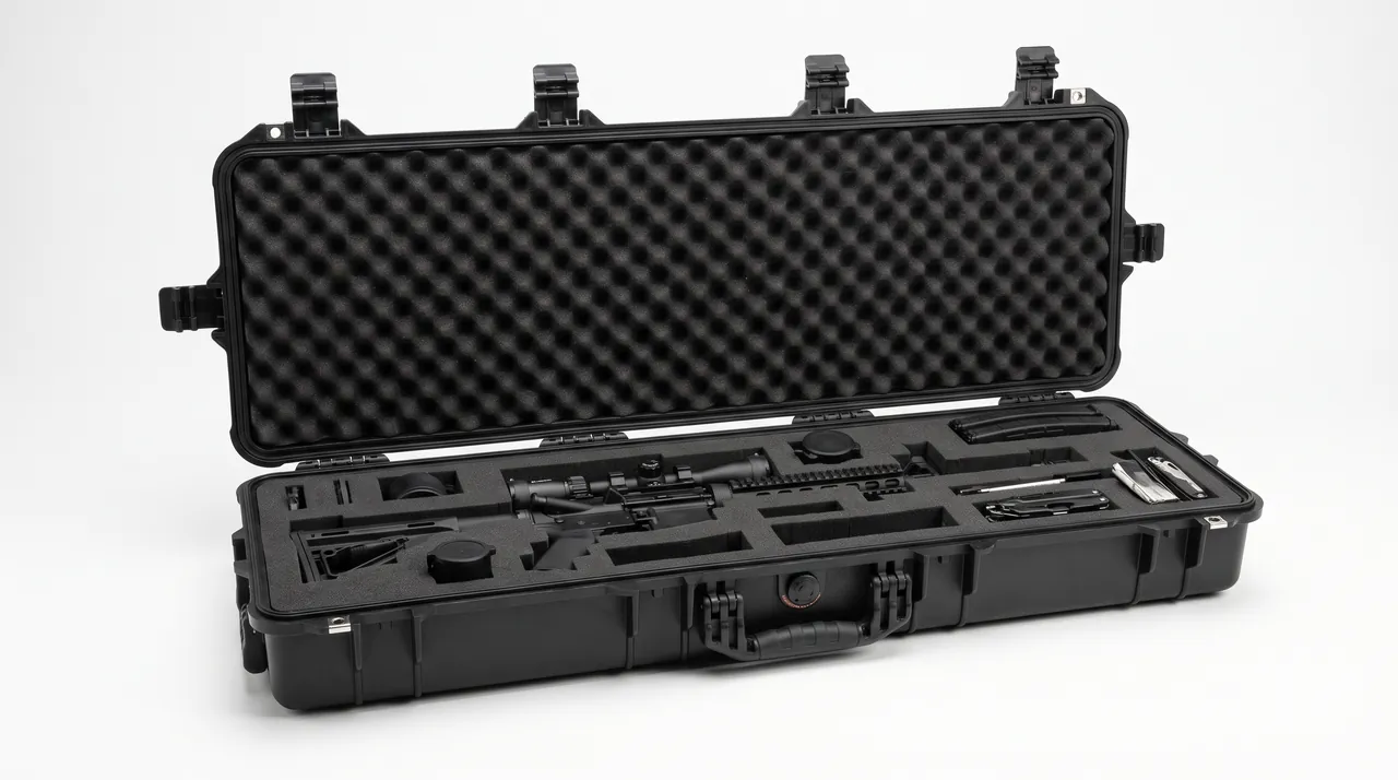
Key points of anti-static box structure: first, the liner uses static-dissipative material (anti-static EVA or conductive foam) in full contact with components; second, a grounding terminal or conductive fastener is provided, which can be connected to a wrist strap or grounding bus before transport; third, the shell itself uses anti-static modified engineering plastic to avoid the shell generating charge that then couples inside; fourth, the lid and liner form a Faraday-cage-like wrap, reducing charge intrusion.
Avoid "local insulation" in design: if a piece of liner or clip is not included in the conductive path, the component there may still accumulate charge. In customization JUNZHJIA treats the liner, fastener, and grounding end as a continuous conductive treatment, and cooperates with the storage compartments of electronic component boxes to ensure every component is in an equipotential environment. A practical detail is the clip and tray: if a PCB sits in a plastic clip that is not part of the conductive path, the board edge may float at a different potential than the liner, so the clip should also be dissipative or conductive, and the design review should trace the path from every contact point back to the ground terminal.
Seam and Interface Treatment of EMI-Shielded Cases
The short board of shielding is the seam. Even if the material SE is high, box lid seams, latch holes, and cable outlets become electromagnetic leakage points if not handled properly. Common measures: add conductive gaskets (conductive silicone, metal spring), use conductive coating to continuously cover seams, and add ferrite rings or filter connectors to cables.
Latches and pivots should have conductive bridging so continuous conductivity is maintained after opening and closing. For field repair boxes that open frequently, refer to the durable structure design of a vehicle maintenance toolbox, integrating the shielding layer with the mechanical structure to avoid coating falling off after repeated opening. The cable interface deserves special attention: an unfiltered cable passing through a shielded wall can carry more interference than the wall blocks, so use feed-through filters or ferrite chokes sized to the frequency of concern, and verify the assembly, not just the bare case, in the shielding test.
Typical Application Scenarios
Anti-static boxes and EMI-shielded cases are widely used in: chip and bare-board transport, sensor module transit, RF and communication board carry, medical electronics repair, and field metering instrument protection. For equipment with high-precision ADC or low-level signals, electromagnetic shielding is especially critical. Combined with the usage scenario of medical equipment boxes, requirements can also include easy-to-disinfect and non-shedding liner while retaining anti-static and shielding capability.
The selection differs by sensitivity: a bare memory module mainly needs anti-static handling; an RF receiver front-end needs shielding against band interference; an automotive ECU may need both plus wider temperature range. Defining the dominant risk first avoids paying for shielding you do not need or skipping anti-static that you do. When in doubt, specify both and ask the supplier for the test evidence for each separately so acceptance is unambiguous.
Synergy with Cushioning Liners
Static, electromagnetic, and mechanical are three independent risks. A protective box that only does anti-static while ignoring drop cushioning will still physically damage components in transit. Therefore a "anti-static/shielding layer + cushioning liner" combination is recommended, borrowing the cushioning design of shock-proof boxes and EVA-liner cases: add slow-rebound foam under the conductive liner so the same box solves both ESD and impact.
The layering order matters: the component should contact the static-dissipative layer directly, then the cushion layer beneath absorbs shock without introducing a charge-generating interface. If the cushion itself is a high-tribocharge foam, it can recharge the board during vibration, so the foam should also be low-tribocharge or separated by a dissipative film. In a shielded case, the cushion must not lift the lid off its conductive gasket, so the total liner thickness is a shared constraint between the shock and shielding designs and should be settled in the same 3D layout.
Synergy with Waterproof Sealing
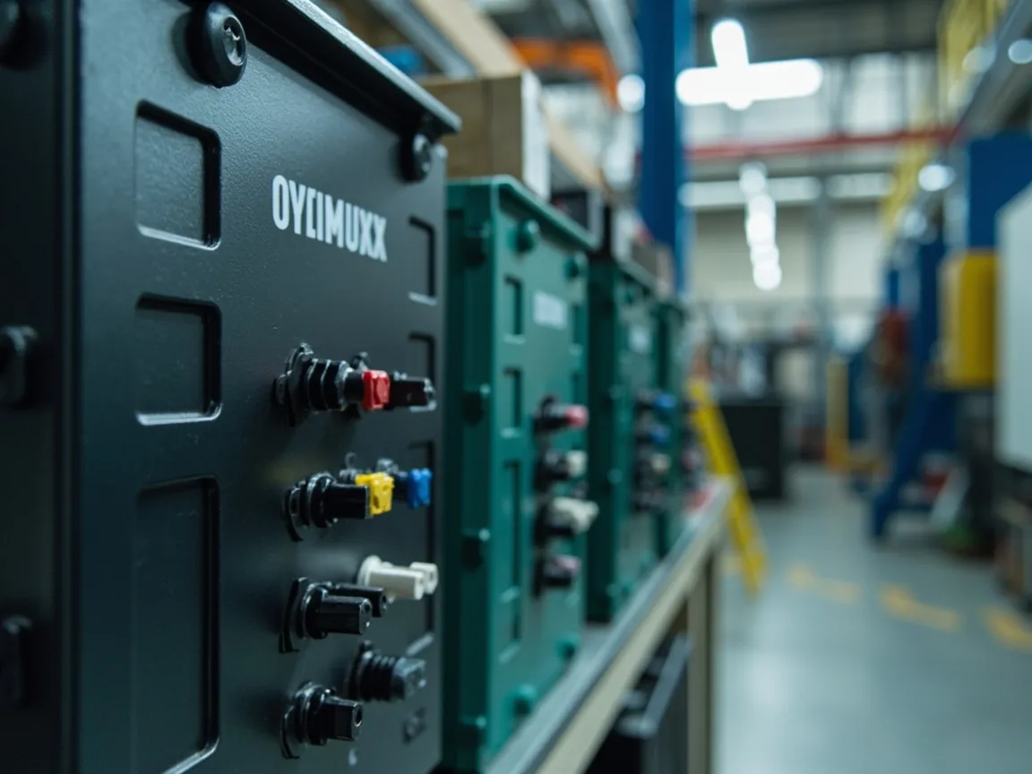
Outdoor and humid environments also need waterproofing. The anti-static layer and sealing layer do not conflict structurally: the sealing ring is placed at the shell seam, the conductive layer at the inner wall; the two belong to different interfaces. But note the conductive coating must not block the sealing ring compression, nor affect lid closure due to coating. When paired with the sealing structure of a plastic waterproof box, the inner shielding layer and shell sealing ring should be co-designed in a 3D model to avoid mutual interference.
A subtle point is grounding through the seal: a wet environment can change surface leakage, so a box that relies on shell conductivity for grounding may behave differently when damp. For such cases, keep a dedicated grounding terminal that does not depend on the sealing interface, and verify resistance both dry and after a damp soak. This keeps the anti-static function independent of the waterproof function, which is the safer design when both are required.
Selection Parameter Checklist
When procuring anti-static/shielding protective boxes, it is recommended to check the following parameters: liner surface resistance range, grounding method, shielding effectiveness SE (note frequency point), continuous conductive coverage, material temperature and flame-retardant grade (UL94), box IP grade, accommodated component size and weight, and whether custom liner and OEM supply are supported. Write these into the specification to facilitate supplier quotation and acceptance.
A compact checklist helps avoid omissions: (1) surface resistance of liner and shell within the stated band; (2) a continuous conductive path from every contact to the ground point, with no floating clips; (3) SE curve with frequency points covering the bands of concern; (4) seam and cable treatment documented and tested on the assembled box; (5) temperature and flame-retardant grades if the case is used near heat or live parts; (6) IP grade if used outdoors; (7) custom liner and OEM/ODM support with traceable test files. Treating this as a release gate, not a wish list, is what separates a qualified protective box from a generic plastic box with a marketing label.
JUNZHJIA Anti-Static and Shielding Custom Capability
JUNZHJIA can provide customized anti-static boxes and EMI-shielded cases: conductive or anti-static modification on EVA base material, liner laminated with metallized shielding layer, configuration of grounding terminals and conductive fasteners, and support for OEM/ODM batch supply. For electronics, medical, and communication scenarios, it can also cooperate with the storage compartments of electronic component boxes for integrated design, delivering a documentation package including surface resistance and shielding effectiveness test descriptions, meeting incoming and outgoing quality traceability.
In customization, JUNZHJIA usually starts from the component sensitivity and the deployment environment, then proposes a liner-shielding-seal combination and validates it by sample before mass production. Because ESD and EMC are verified by different tests, the proposal states which standard each property is judged against, so the customer can accept them independently. For export or long-storage equipment, the spare-part plan includes conductive fasteners and gaskets so the box can be maintained over its service life, and the material certificate is kept with the batch record for audit.
Common Application Mistakes
First, believing "plastic boxes are always insulating": through modification, engineering plastic can fully possess static-dissipative capability. Second, looking only at material not path: without grounding or continuous conductivity, a single conductive liner has limited effect. Third, ignoring seams: the seam of a shielding box is more critical than the material. Fourth, equating anti-static with shielding: the two standards and tests are completely different and must be verified separately. Fifth, electronic component boxes that only do storage without protection will still fail from ESD/EMI in transit. Sixth, specifying only a single number — a "10^9 Ω" liner or a "60 dB" box — without the accompanying test condition, which makes the claim impossible to verify on arrival.
FAQ
Q: Are anti-static boxes and EMI-shielded cases the same thing? A: No, they are not the same; they solve different problems. An anti-static box targets electrostatic discharge (ESD), using static-dissipative or conductive materials and a grounding path to safely release surface static charge on components, avoiding concentrated discharge that breaks down sensitive structures like gate oxide. An EMI-shielded case targets electromagnetic interference (EMI/EMS), using a highly conductive continuous covering layer to attenuate external electromagnetic fields and protect sensitive circuits from interference. Many high-value electronics transport scenarios need both, so the anti-static liner and metallized shielding layer are often combined into the same box for dual electrostatic and electromagnetic protection. Concretely, the anti-static function is about charge on the surface and human handling, while shielding is about waves in the air; a box can pass one test and fail the other, so specify and verify each independently rather than assuming a single "protected" label covers both. The two must be tested by different standards — ESD by IEC 61340 / ANSI/ESD S20.20 and shielding by an SE measurement — so do not assume passing one implies the other.
Q: What surface resistance is appropriate for a protective box liner? A: Transport protective box liners usually fall in the static-dissipative zone; the experience value recommends controlling liner surface resistance between 10^6 and 10^9 Ω. This range allows static charge to dissipate evenly on contact without the spark risk from too-low resistance causing overly fast discharge. The specific value should also combine component sensitivity and whether grounding exists: if the box is reliably grounded, resistance can bias to the lower limit to enhance dissipation; if grounding is impossible, ensure it stays in the dissipative zone without charge accumulation. In acceptance, it is recommended to use a surface resistance tester for per-batch sampling and record, and also run a charge-decay test because a liner that rubs the component during transit can regenerate charge even if its point resistance is compliant. A common mistake is to chase the lowest possible resistance thinking "more conductive is safer"; below about 10^4 Ω the discharge becomes fast enough to spark, and the liner starts behaving like a bare conductor that can couple noise into sensitive circuits, so the dissipative band is a deliberate compromise, not a lower-is-better race. When specifying, also decide whether you need a static-dissipative or a conductive (lower resistance) liner based on how the box is used: a dissipative liner is the default for transit and handling because it bleeds charge slowly and safely, while a conductive liner is chosen where very fast equalization is required and the environment is otherwise controlled. Mixing them without thought can create a path that is too aggressive. Record the chosen band on the drawing and on the incoming inspection sheet so the receiving team tests the right range instead of a generic pass. A practical tip is to mark the liner grade visibly on the box so operators in the field do not swap a dissipative liner for a conductive one by mistake during repairs.
Q: How to read the shielding effectiveness of an EMI-shielded case? A: Shielding effectiveness (SE) is expressed in decibels (dB); the larger the value, the stronger the attenuation of external electromagnetic fields. Common requirements range from 40 to 80 dB, depending on the protected frequency and equipment sensitivity. When viewing the metric, the corresponding frequency point must be noted, because the SE of the same material at 1 MHz and 1 GHz may differ greatly. High-frequency electric fields are easier to shield; low-frequency magnetic fields are harder and need high-permeability or metal liner. In procurement, require the supplier to provide an SE test curve with frequency points, not just a vague number, and confirm the curve covers the bands your equipment actually operates in, because a high number at the wrong frequency is meaningless for your risk. Also check whether the quoted SE is for the bare wall or the assembled box: a wall may show 80 dB while the assembled case with its seams and connectors drops to 50 dB, so the number that matters is the one measured on the finished product with all openings closed and cables attached as used.
Q: Does an anti-static box need grounding? A: Grounding is recommended but not absolutely mandatory. Grounding forms a definite dissipation path and is the most robust solution, especially suitable for workshop transit and repair scenarios, where the box can be connected to a wrist strap or grounding bus. For transit where grounding is impossible, the protective box relies on internal continuous conductive path and static-dissipative liner to keep components in an equipotential low-potential-difference environment, which also suppresses discharge. The key is that liner, fastener, and grounding end must be continuously conductive, with no local insulation, otherwise charge may still accumulate there. A good design keeps a dedicated ground terminal that works whether or not the environment provides a bus, so the dissipation path is never accidentally broken. In practice, grounding should be built as a feature of the workflow, not left to chance. When a box is used on a bench, clamp the ground lead to the same bus as the operator's wrist strap so the component, the box, and the person share one potential; this removes the most common discharge path that damages parts. For field service where no bus exists, a conductive tote that returns to the bench still helps because it prevents the part from floating at a different potential than the receiving equipment. The mistake to avoid is treating grounding as optional on paper but missing in reality: a box labeled anti-static that sits on a non-conductive cart with no ground path gives almost none of the intended protection. Document the ground method in the work instruction and audit it, because the best liner cannot help if the surrounding process defeats it.
Q: How to treat the seam of a shielding box effectively? A: The seam is the short board of shielding effectiveness and must be treated with continuous conductivity. Common measures include adding conductive gaskets (conductive silicone or metal spring) at the lid seam, continuously covering latches and pivots with conductive coating, and adding ferrite rings or filter connectors at cable outlets. The design principle is "maintain conductive continuity after opening and closing," so latches and pivots should have conductive bridging. For field boxes that open frequently, the shielding layer should be integrated with the mechanical structure to avoid coating falling off after repeated opening and causing leakage. Also treat the cable gland as part of the shield: an unfiltered cable can carry more interference than the wall blocks, so use feed-through filters or ferrite chokes and test the assembled box, not just the bare shell. A useful acceptance step is to open and close the lid several times and re-measure SE, because a gasket that compresses unevenly or a coating that cracks at a hinge can quietly open a leakage path that only appears after field use rather than on a fresh sample.
Q: Why must electronic components be anti-static in transport? A: Modern electronic components such as CMOS, IGBT, and RF front-ends are extremely sensitive to static; a discharge of just tens of volts can burn the gate oxide or cause latent damage that makes the component fail prematurely later, with no obvious appearance trace and difficult rework traceability. During transport, personnel handling, friction charging, and dry environment all accumulate charge, and ordinary insulating boxes instead leave charge nowhere to dissipate. Therefore electronic component transport should use electronic component boxes paired with anti-static boxes, keeping components in an equipotential dissipative environment throughout, reducing failure rate from the supply chain source. The cost of one latent failure in the field usually far exceeds the price difference of a qualified anti-static box, which is why the protection is treated as mandatory in automotive and medical supply chains.
Q: Can it be both anti-static and cushioning? A: Yes, and the combination is recommended. The common approach is to stack slow-rebound foam under the conductive or anti-static EVA liner, giving the box both static dissipation and impact absorption; a layered liner can also be used, with the upper layer as static-dissipative contact and the lower layer as mechanical cushion. The point is the conductive layer must not sacrifice the cushion stroke, and the cushion layer must not block the conductive path; the two must be coordinated in 3D layout. The cushion foam itself should be low-tribocharge so vibration does not recharge the board, and it should not lift the lid off any conductive gasket in a shielded version. Referring to the cushioning design of shock-proof boxes and EVA-liner cases can solve both ESD and drop risks together.
Q: How to accept a batch of anti-static boxes? A: Acceptance should cover material, structure, and documentation. For material, use a surface resistance tester to sample the liner and shell resistance to see if they fall in the specification range; for structure, check whether the grounding terminal, conductive fastener, and liner are continuously conductive with no local insulation; for function, run ESD simulated discharge and (if required) shielding effectiveness test. For documentation, require the supplier to provide a test description package including surface resistance, SE frequency points, and material grade. Suppliers like JUNZHJIA that support OEM/ODM can usually deliver a traceable documentation package for batch quality control. It is also wise to keep one box from each batch as a golden sample and re-verify it periodically, because material and coating can drift over a long production run, and a one-time incoming inspection does not guarantee that box number ten thousand has the same performance as box number one. For high mixes, also reconcile the incoming test with the supplier's process control records so a passing sample is backed by a stable process, not just luck on that unit.
Q: What should be noted for outdoor shielding boxes? A: Outdoor use must consider temperature zone, sealing, and mechanical durability at the same time. Low temperature makes some coatings brittle and reduces adhesion, so select temperature-resistant material following the logic of low-temperature protective boxes; humid environments need waterproof sealing, and the conductive coating must not block the sealing ring; frequent outdoor opening and bumping require the shielding layer integrated with the mechanical structure to avoid falling off. In addition, the outdoor electromagnetic background may be strong, so the SE metric should leave sufficient margin. Overall, an outdoor shielding box is a system problem of mechanical, electrostatic, electromagnetic, temperature, and humidity factors, and each factor should be specified with its own test condition rather than assumed from a single label. Practically, write the worst-case conditions into the order — lowest and highest temperature, IP grade for rain and dust, and the field EMI spectrum — because each of those factors changes how the shielding and anti-static layers must be built, and a box designed for a benign indoor lab will not survive a dusty, freezing, RF-noisy site no matter how good its catalog numbers look on paper.
Conclusion and Related Reading
Anti-static boxes and EMI-shielded cases guard the "electrostatic safety" and "electromagnetic safety" of components respectively; they complement rather than replace each other. During selection, check surface resistance, shielding effectiveness, seam treatment, and synergy protection item by item and write them into the purchase specification, so as to minimize ESD/EMC failure risk.
Related Reading