

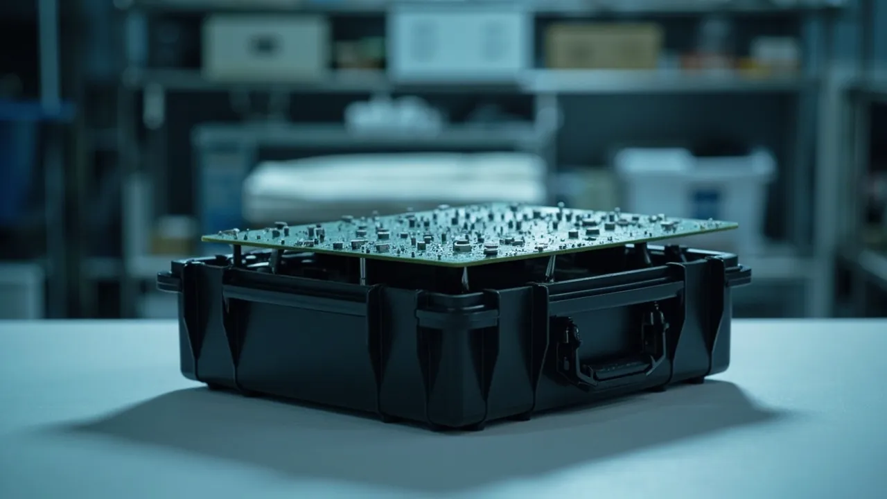
The short answer: an ESD protective case is not simply a case moulded in black plastic. It has to satisfy four things at once — material resistance falling in the dissipative or conductive band, a defined charge bleed path to ground, sufficient electrostatic shielding for the devices inside, and resistance that stays measurable and verifiable over the whole service life. A case that does only the first can measure "compliant surface resistance" in a laboratory and still fail on a real production line, because the insert is ordinary foam, the latch is an unbonded metal part, or there is no reliable ground path at all. The governing principle of ESD protection is that charge must be able to leave in a controlled way — not that the material looks black.
This article is written for buyers and process engineers in electronics manufacturing, semiconductors, medical devices and defence supply chains. It sets out a usable technical requirement framework: the thresholds that separate conductive, dissipative and insulative materials; how surface resistance, volume resistance and charge decay are measured and what limits apply; what the IEC 61340 series, ANSI/ESD S20.20 and MIL-PRF-81705 each govern; how carbon black, carbon fibre and permanent antistatic additives differ; design points for conductive inserts, ground paths and shielding; how ESD requirements can coexist with an IP67 rating; and how to handle incoming testing and life-cycle management. All values are typical or commonly used industry figures, and the binding limits should always follow the customer's standard system and the actual sensitivity class of the devices concerned.
Contents
- The short answer: four things ESD protection must do
- Three material classes: conductive, dissipative and insulative
- Three key parameters: surface resistance, volume resistance and charge decay
- Standards: IEC 61340, ANSI/ESD S20.20 and MIL-PRF-81705
- Base resin routes: carbon black, carbon fibre and permanent antistatic additives
- ESD design for inserts: conductive foam and conductive thermoformed trays
- Ground paths and charge bleed design
- Shielding: dividing the job between the case and the bag
- Making ESD and IP67 compatible
- Details that get overlooked: hardware, labels and isolated conductors
- Test methods and incoming acceptance
- Use, cleaning and life-cycle management
- Application configurations and a selection table
- Frequently Asked Questions
- Conclusion and Related Reading
The short answer: four things ESD protection must do
Strip the requirement back and it is four things, none optional.
| Element | Problem it solves | Key metric | Common omission |
|---|---|---|---|
| --- | --- | --- | --- |
| Material resistance | Whether charge drains away rather than accumulating | Surface resistance within the conductive or dissipative band | Judging by colour instead of resistance |
| Bleed path | Where the charge finally goes | Groundability, and controlled connection resistance | Case is conductive but cannot be grounded |
| Shielding | Whether external fields are blocked | Shielding attenuation or energy penetration | Confusing antistatic with shielding |
| Verifiability | Whether performance survives use | Periodic re-test of resistance and decay | Never re-tested after delivery |
Why do all four matter? Take a typical failure. The case is carbon-black filled conductive PP with compliant surface resistance. The insert, however, is ordinary PE foam, an insulator. Devices rub against the foam, charge is generated and cannot bleed away, and because the case has no grounding feature the charge can only neutralise slowly through the air. The case material "passes" while the devices are still damaged. That is why ESD requirements must address the whole packaging system, not just the case material.
A second common misunderstanding conflates antistatic with shielding. Antistatic means the material does not readily generate or accumulate charge and can bleed it away. Shielding means blocking external electrostatic fields from reaching the contents. The two correspond to different test methods and different material structures. A purely dissipative material bleeds charge well but has limited ability to block fast transient fields, whereas a metallised shielding layer can hold an external field out within tens of nanoseconds. A complete ESD package usually needs both functions stacked.
Three material classes: conductive, dissipative and insulative
Every ESD requirement starts with material resistance classification. The industry classification is as follows; thresholds follow the IEC 61340 series and related ANSI/ESD standards, which differ slightly in absolute values between systems, and the figures below are the commonly used industry readings.
| Class | Surface resistance (Ω) | Charge behaviour | Typical materials | Typical use |
|---|---|---|---|---|
| --- | --- | --- | --- | --- |
| Conductive | below 1×10⁴ | Very fast bleed, almost no accumulation | Carbon-black filled PP/PE, metallised materials, metals | Grounded containers, shielding layers, conductive mats |
| Dissipative | 1×10⁴ to below 1×10¹¹ | Slow, controlled bleed | Permanent antistatic PP, lightly filled compounds | Totes, inserts, work surfaces |
| Insulative | 1×10¹¹ and above | Accumulates, cannot bleed | Ordinary PP, PE, ABS, PC, EVA foam | General packaging, not for ESD-sensitive items |
Why separate conductive from dissipative, rather than simply using the most conductive option? Because bleeding too fast is itself a risk. When a charged device touches a low-resistance conductor, charge releases in an extremely short time, producing a larger discharge current that can damage sensitive devices — the mechanism known as fast discharge damage. A dissipative material bleeds charge at a controlled rate, keeping the discharge current inside a safe range. So for surfaces in direct contact with devices, dissipative materials are usually preferred over strongly conductive ones, while strongly conductive materials are better used as shielding layers and ground paths.
Insulative materials are not banned in ESD areas; they are managed. General packaging uses large amounts of insulative plastic quite legitimately, provided it does not directly contact sensitive devices and does not generate high fields near them. Standard practice on a production floor is to keep both the distance from devices and the surface potential of insulators within defined limits. The governing rule is that any insulator close to a sensitive device must be assessed for electrostatic risk, never assumed harmless.
Three key parameters: surface resistance, volume resistance and charge decay
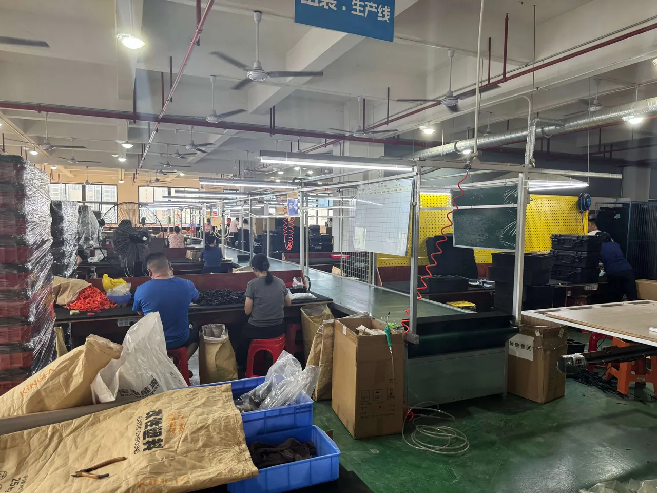
The most common question in ESD case procurement is "what is the surface resistance?" That single number is not enough.
Surface resistance. This describes how easily charge moves along the material surface and is the most widely used classification basis. Methods include parallel-electrode and concentric-ring configurations, as set out in ESD STM11.11 and IEC 61340-2-3. Test voltage and electrode configuration materially change the result, so the technical agreement must state the test standard, electrode type, test voltage and preconditioning, including temperature and humidity.
Volume resistance. This describes how easily charge passes through the material thickness. For load-bearing walls, spacers and conductive inserts, volume resistance reflects real bleed capability better than surface resistance. ESD STM11.12 is the usual reference.
Charge decay time. A defined initial voltage is applied to the surface and the time to decay to a specified proportion is measured. This is the metric closest to reality, because it captures both the resistive and capacitive behaviour of the material. A common industry requirement is decay from 1000 V to 100 V within two seconds, with stricter programs specifying shorter limits. On lines with frequent handling and fast rubbing, decay time deserves a place in the agreement more than surface resistance does.
Three conditions that are easy to overlook but critical.
- Temperature and humidity. Resistance of many materials, especially those relying on hygroscopic antistatic agents, changes markedly with humidity. State the test environment in the agreement, commonly both 12 percent ±3 percent RH as the harsh low-humidity case and 50 percent ±5 percent RH as the normal case.
- Test voltage. Commonly 10 V for dissipative materials and 100 V for conductive and insulative materials. Using the wrong voltage produces a completely different answer.
- Surface preparation. Whether the measurement point is clean and free of mould release residue directly affects the reading. Clean the test points by the standard method before incoming testing.
| Parameter | What it reflects | Common test standards | Common limits (industry) | Test condition notes |
|---|---|---|---|---|
| --- | --- | --- | --- | --- |
| Surface resistance | Surface bleed capability | ESD STM11.11, IEC 61340-2-3 | Dissipative 1×10⁴ to below 1×10¹¹ Ω | Electrode type, voltage, humidity |
| Volume resistance | Through-thickness bleed | ESD STM11.12 | Conductive materials commonly below 1×10⁵ Ω·cm | Contact area, applied pressure |
| Charge decay | Combined bleed performance | IEC 61340-2-1 and common industry methods | 1000 V to 100 V within 2 s (common) | Initial voltage, humidity |
| Shielding attenuation | Blocking external fields | MIL-PRF-81705 classification, ESD STM11.31 | Per agreed class | Test fixture and probe |
| Ground connection resistance | Whether the bleed path works | Field measurement | Per site EPA requirements | Joint, cable and earth electrode |
Standards: IEC 61340, ANSI/ESD S20.20 and MIL-PRF-81705
Three systems each cover a different segment, and mixing them carelessly produces gaps or duplication.
The IEC 61340 series. This is the International Electrotechnical Commission family of electrostatic standards. The most cited parts are:
- IEC 61340-5-1, the general requirements for protecting electrostatic-sensitive devices and for establishing and managing an EPA, an electrostatic protected area.
- IEC 61340-5-3, the classification and performance requirements for packaging, and the most directly relevant part for cases, inserts and bags.
- IEC 61340-2-1, test methods for charge decay.
- IEC 61340-2-3, test methods for resistance and resistivity, the operational basis for applying thresholds.
ANSI/ESD S20.20. Published by the Electrostatic Discharge Association, this is the most widely applied EPA management standard in electronics manufacturing. It covers EPA establishment, personnel grounding, work surfaces, flooring, packaging and marking. The most common practical wording in case procurement is "the product meets the packaging requirements of ANSI/ESD S20.20," supported by reference to specific packaging test standards such as the ESD STM11 series.
MIL-PRF-81705. This is the US military performance specification for flexible electrostatic shielding packaging materials, widely used in defence and aerospace supply chains. It classifies materials by performance, with the principal distinctions being water vapour barrier capability and electrostatic shielding capability, for example by energy penetration expressed in the low nanojoule range for higher shielding classes. Customers in defence or aerospace systems will normally require a classification report to this specification. Cases and bag materials in that system must declare their type and shielding class.
| Standard | Scope | What it means for case procurement | How it is usually cited |
|---|---|---|---|
| --- | --- | --- | --- |
| IEC 61340-5-1 | General EPA requirements | Defines protection conditions at the point of use | Basis for a site ESD programme |
| IEC 61340-5-3 | Packaging classification and performance | Core basis for cases, inserts and bags | Written directly into the technical agreement |
| IEC 61340-2-1 / 2-3 | Decay and resistance test methods | Specifies how to measure and judge | Attached to the test method clauses |
| ANSI/ESD S20.20 | EPA establishment and management | The mainstream requirement for electronics customers | Basis for a declaration of conformity |
| ESD STM11 series | Material and packaging test methods | Surface and volume resistance, shielding | Source of specific methods and limits |
| MIL-PRF-81705 | Flexible shielding packaging performance | Essential for defence and aerospace programs | Reports issued by type and class |
Practical advice for buyers. Do not write only "antistatic." Write a three-part clause: the reference standard, such as IEC 61340-5-3; the performance class, conductive or dissipative; and the specific limits with the test method. For example: "The case material shall be dissipative, with surface resistance measured to ESD STM11.11 at both 12 percent ±3 percent RH and 50 percent ±5 percent RH, falling within 1×10⁴ Ω to below 1×10⁹ Ω under both conditions." Written that way, any supplier can align unambiguously.
Base resin routes: carbon black, carbon fibre and permanent antistatic additives
Plastics are insulators, so ESD performance requires modification. The three main routes behave quite differently.
Route one: carbon black filling. The mainstream and lowest-cost approach. Conductive carbon black is compounded into PP, PE or ABS to form a conductive network, giving surface resistance in the range of 1×10³ to 1×10⁶ Ω. The advantages are permanence, independence from humidity and controllable cost; the drawbacks are that only dark colours are possible, usually black, and that carbon black reduces toughness, impact strength and weatherability. For load-bearing parts, drop and stacking performance must be re-qualified.
Route two: carbon fibre filling. Chopped carbon fibre forms the conductive network. Compared with carbon black, it affects mechanical properties less at the same loading and can actually increase stiffness, which suits load-bearing parts that must be both strong and conductive. The drawbacks are clearly higher cost, a visible fibre texture on the surface, and more tool wear during processing.
Route three: antistatic additives, migrating or permanent. Migrating antistatic agents rely on migrating to the surface and forming a hygroscopic layer to bleed charge. They are cheap but humidity dependent, and they wash or wipe away over time, so performance decays. Permanent, polymer-type antistatic agents form an interpenetrating network in the matrix, do not migrate and do not wash out, giving more stable performance for long-life, frequently cleaned applications.
| Modification route | Typical surface resistance | Humidity dependence | Mechanical effect | Appearance limits | Best fit |
|---|---|---|---|---|---|
| --- | --- | --- | --- | --- | --- |
| Carbon black filled | 1×10³ to 1×10⁶ Ω | Low (permanent) | Noticeable toughness loss | Dark or black only | Totes, load-bearing cases, pallets |
| Carbon fibre filled | 1×10⁴ to 1×10⁸ Ω | Low (permanent) | Small effect, stiffness can rise | Visible fibre texture | High-stiffness load parts, precision cases |
| Permanent antistatic additive | 1×10⁹ to 1×10¹¹ Ω | Low | Small effect | Light colours possible | Inserts, exterior parts, cleanroom use |
| Migrating antistatic additive | 1×10⁹ to 1×10¹¹ Ω | High | Small effect | Light colours possible | Single-use packaging, short-term totes |
| Metallised or coated layer | below 1×10⁴ Ω (shielding) | Low | Depends on substrate | Silver or metallic | Shielding films, shielding inserts |
Selection guidance. Load-bearing shells should use carbon black or carbon fibre filling. Parts needing light colour or cleanroom suitability, such as inserts and divider panels, can use permanent antistatic additives. Shielding requirements are met with a metallised layer or conductive coating. General resin selection logic is covered in choosing plastics for protective cases.
ESD design for inserts: conductive foam and conductive thermoformed trays
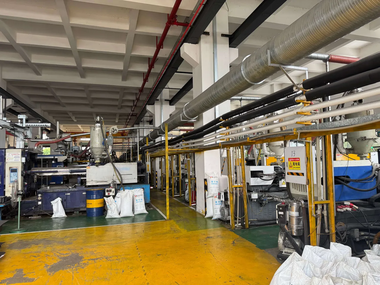
Inserts are the most commonly overlooked element and carry the highest ESD risk, because they touch the devices.
Why inserts matter so much. Friction between the device and the insert is the principal source of charge generation. If the insert is ordinary insulative EVA or PE foam, the charge generated by rubbing cannot bleed away and builds a high potential right beside the device. A conductive case cannot help, because the charge is trapped between the insulative insert and the device.
Three workable insert solutions:
- Conductive PE foam. Carbon black is compounded into PE foam to bring surface resistance into the dissipative or conductive band. It balances cushioning and ESD performance, and its forming processes resemble those for ordinary foam; the drawbacks are typically a black colour and slightly lower resilience from the conductive filler.
- Conductive thermoformed trays. Conductive or dissipative sheet is thermoformed into a tray with good dimensional accuracy, suited to regular device outlines. The advantages are precise fit to the device, stackability and cleanability; the drawback is higher adaptation cost for irregular shapes.
- Conductive fabric or coated liners. A conductive coating on fabric or film suits applications needing both soft conformity and shielding. The continuity of the conductive path across folds must be verified specifically, because repeated folding can crack the coating.
Three insert design points:
- The insert and the device should form a continuous bleed path. The ideal is a four-stage chain: device to insert to case to ground, with resistance controlled at each stage.
- Avoid large areas of rubbing. Constrain device movement with compartments or locating features, attacking charge generation at source, which is more effective than relying on bleed alone.
- Test the insert separately. Measuring the case alone is not enough. Comparative foam data is in foam material comparison for case inserts, and custom insert forming is covered in custom EVA foam insert processing.
Ground paths and charge bleed design
A conductive case is only the first step; the charge must ultimately go somewhere.
Three levels of grounding:
- The case can be grounded. There should be a defined grounding point, commonly a moulded-in metal stud, a conductive pad or a metal boss. Contact resistance at that point must be controlled and cannot rely on pressing against a plastic surface.
- The supporting surface can be grounded. If the case sits on a workbench, shelf or trolley, those surfaces should be part of the EPA. A conductive case on an insulative bench has nowhere for its charge to go.
- People and tools can be grounded. Operators ground through wrist straps or conductive footwear, and tools and equipment are brought into the EPA as well. This is the user's responsibility, but case design should support it, for example by providing a point where a wrist strap can be tested conveniently.
A practical judgement call: does a case need to be grounded at all times? Not necessarily. A dissipative material will still bleed charge slowly through air and contact surfaces even when not grounded, whereas a conductive material left ungrounded can become a floating conductor that discharges rapidly on touching another object. Therefore:
- Dissipative cases suit handling and storage where grounding cannot be guaranteed.
- Conductive cases need explicit grounding management so they do not become floating conductors.
That distinction matters a great deal and is the most commonly skipped selection criterion.
Shielding: dividing the job between the case and the bag
Shielding and antistatic are different functions, and cases and bag materials play different roles.
What is being shielded against? Mainly external electrostatic fields and the transient fields produced by electrostatic discharge. When a discharge occurs near a charged device, the rapidly changing field can induce a voltage on device leads. A shielding structure attenuates that field before it reaches the device.
Common shielding implementations:
- Metallised film or metallised liner. A conductive shielding layer of aluminium or another metal on film or liner. Shielding performance is strong and weight is low; the weakness is that the coating has limited abrasion resistance and repeated rubbing can break continuity.
- Conductive coating. A conductive layer applied to the inside of the case or to an insert. Relative process simplicity, but adhesion and abrasion resistance must be verified.
- Metal foil laminate. Used where requirements are highest, giving the best shielding at the greatest cost and weight.
Dividing the job. The usual approach is that the case provides structural protection and charge dissipation while the bag or liner provides shielding. That meets the shielding requirement while controlling cost. For more demanding defence and aerospace programs the case itself may need shielding capability, usually via a metallised liner or a conductive liner combined with conductive seals.
How is shielding verified? Commonly by energy penetration or shielding attenuation testing, following ESD STM11.31 or the MIL-PRF-81705 classification method. The agreement must state the method and the acceptance class rather than simply requiring "shielding."
Making ESD and IP67 compatible
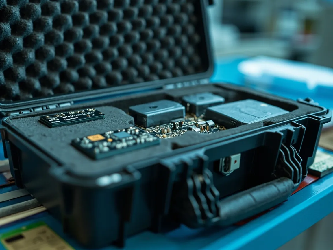
Many applications — outdoor electronics, vehicle electronics, defence equipment — require both ESD and an IP67 rating. The two can coexist, with design trade-offs in three places.
Trade-off one: conductivity of the seals. Ordinary silicone gaskets are insulators and create a break in the case's conductive path. If the case as a whole must be conductive, conductive silicone gaskets are needed, filled with carbon black, nickel-coated graphite or silver-coated glass microspheres. The cost is that conductive gaskets generally have slightly worse compression set than ordinary silicone and are noticeably more expensive. Material differences are covered in choosing gasket and seal materials.
Trade-off two: mechanical effect of conductive fillers. Carbon black reduces impact strength and low-temperature toughness. If the case must also survive drop testing and seal to IP67, wall thickness, ribbing and gasket groove dimensions need compensation. A practical sequence is to validate structure and sealing in an ordinary material first, then re-test in the conductive grade and reinforce where the differences appear.
Trade-off three: the conflict between grounding and sealing. Grounding needs a conductor through the wall, and any penetration is a potential leak path. The recommended approach is to place the grounding feature in a non-sealing area, such as the base or an external boss, realised by insert moulding rather than field drilling. Pressure equalisation and sealing structures interact in the same way, as described in how a pressure equalisation valve works, and rating conditions are set out in understanding the IP67 rating.
If ESD and IP67 genuinely cannot both be met, which takes priority? The deciding factor is the relative sensitivity of the device to moisture versus static. If the device is extremely moisture sensitive, such as certain optical components or assemblies containing hygroscopic materials, sealing comes first. If it is static sensitive and the transport environment carries ESD risk, ESD comes first. The best practice is to settle the priority at project kick-off rather than discovering the conflict at sample stage.
Details that get overlooked: hardware, labels and isolated conductors
ESD cases usually fail on the small parts.
Isolated conductors are the greatest single hazard. Metal latches, hinge pins, nameplates and screws that are not reliably connected to the case's conductive network become isolated conductors. They can acquire induced charge and discharge rapidly when they touch a device or another conductor. Two management rules apply: anything that can be bonded must be bonded into the case's conductive network, and anything that cannot must be replaced with an insulative or dissipative alternative.
Labels and marking. Ordinary paper or plastic labels are insulators, and they are usually placed on the most visible surface. Conductive or dissipative label stock is recommended, with conductive adhesive, so no insulative layer forms between label and case. ESD packaging should also carry standard electrostatic-sensitive marking, with content and position defined on the drawing.
Mould release and cleaning residue. Mould release agents are usually insulative, and residue on the case surface raises surface resistance enough to fail a test. Handle this by requiring suppliers to use release agents suitable for ESD materials, or by adding a cleaning step, and by cleaning test points to the standard method before incoming testing.
Colour and appearance. Carbon-black filled materials are usually black only. If a light colour is required, the permanent antistatic route is the only option, and the achievable resistance usually falls in the dissipative band rather than the conductive band. "Light colour plus strongly conductive" is contradictory in most conventional processes, and the expectation should be aligned at project kick-off.
| Detail | Risk | Design requirement | Verification |
|---|---|---|---|
| --- | --- | --- | --- |
| Metal latch or hinge | Isolated conductor discharging rapidly | Bond to the conductive network, or use dissipative material | Continuity test |
| Label | Insulative layer isolating charge | Conductive label stock with conductive adhesive | Resistance test over the label area |
| Mould release residue | Surface resistance reads artificially high | Specify ESD-compatible release agent or add cleaning | Before and after cleaning comparison |
| Colour | Light colour conflicts with conductivity | Define resistance target and appearance priority | Resistance test and appearance approval sample |
| Insert | Charge trapped beside the device | Conductive or dissipative insert | Separate insert resistance test |
Test methods and incoming acceptance
ESD case testing must be reproducible, with the environment recorded and the criteria stated.
Five mandatory incoming checks:
- Surface resistance. Measured to ESD STM11.11 or IEC 61340-2-3 at the specified temperature, humidity and test voltage. Testing under both low humidity, such as 12 percent ±3 percent RH, and normal humidity, such as 50 percent ±5 percent RH, is recommended, because low humidity is the harshest case.
- Volume resistance. To ESD STM11.12, for load-bearing parts and conductive inserts.
- Charge decay time. To IEC 61340-2-1 or a common industry method, recording the time from 1000 V to 100 V.
- Insert and accessory resistance. Inserts, dividers and label areas should be measured separately to confirm a continuous bleed path through the assembly.
- Appearance and construction. Confirm no mould release residue, no damage to conductive layers, and no unbonded metal parts.
Type testing, at design freeze and after any change, should add:
- Shielding performance to ESD STM11.31 or the MIL-PRF-81705 classification method.
- Drop, vibration and stacking tests, because conductive fillers change mechanical behaviour.
- Ingress protection testing to IEC 60529 or GB/T 4208 where an IP rating is also required.
- Resistance re-test after thermal and humidity cycling, to confirm long-term stability.
- Cleaning and wiping durability, simulating field cleaning to confirm resistance does not drift beyond limits.
| Test item | Stage | Method | Judgement point |
|---|---|---|---|
| --- | --- | --- | --- |
| Surface resistance | Incoming and type | ESD STM11.11 / IEC 61340-2-3 | Passes at both humidity conditions |
| Volume resistance | Incoming and type | ESD STM11.12 | Judged by material class |
| Charge decay | Incoming and type | IEC 61340-2-1 | 1000 V to 100 V within the agreed time |
| Shielding | Type | ESD STM11.31 / MIL-PRF-81705 | Reaches the agreed class |
| Continuity | Incoming | Multimeter continuity test | Metal parts connected to the case network |
| Wipe durability | Type | Re-test after the agreed wipe count | Resistance still within limits |
| Resistance after cycling | Type | Re-test after thermal and humidity cycling | Change within the agreed band |
Acceptance criteria and sampling can follow the general AQL framework, treating surface resistance, volume resistance, decay time and continuity as functional characteristics, and appearance and marking as visual ones. The method is set out in acceptance criteria and AQL sampling for custom cases.
Use, cleaning and life-cycle management
ESD performance degrades in service, so it needs whole-life management.
Cleaning. Use neutral cleaners and lint-free cloths, and avoid cleaners containing silicone oil or wax, which leave an insulative film on the surface. Let parts dry naturally and re-test surface resistance at intervals.
Re-test intervals. Set them by duty level: quarterly or half-yearly for high-frequency handling, annually for general storage. Records must include temperature and humidity, or the data cannot be compared.
Factors affecting life.
- Carbon-black filled materials are stable; the main risks are surface contamination and mechanical damage such as scratches or impact that break the conductive path locally.
- Permanent antistatic additives are stable, though prolonged high temperature can affect the network.
- Migrating antistatic additives degrade fastest; wiping and washing accelerate loss, so they are not recommended for long-life applications.
- Metallised coatings mainly suffer coating wear and delamination, especially at repeatedly rubbed locations.
Deciding between derating and scrapping. When re-tested resistance exceeds the limit, the conductive layer is visibly damaged, or metal part continuity cannot be restored, the case should be derated, for example to non-sensitive use, or scrapped. Do not attempt a quick fix by spraying on more antistatic agent: it normally cannot restore shielding capability and makes performance unpredictable.
Application configurations and a selection table
| Application | Case material | Insert | Shielding | Grounding | Key caution |
|---|---|---|---|---|---|
| --- | --- | --- | --- | --- | --- |
| PCB totes | Carbon-black PP, dissipative or conductive | Conductive PE foam | Medium | Groundable | Insert must be bonded to the case |
| Semiconductor storage | Conductive or dissipative PP | Conductive thermoformed tray | High | Grounding required | Eliminate isolated conductors |
| Precision instrument transport | Dissipative PP with conductive liner | Conductive foam plus tray | High | Groundable | Balance cushioning and bleed |
| Defence and aerospace | Conductive PP or metallised liner | Conductive foam | Very high, classified | Grounding required | Requires MIL-PRF-81705 class report |
| Field service tools | Dissipative PP | Conductive foam or conductive grid | Medium | Not always groundable | Prefer dissipative over strongly conductive |
| Medical electronics | Dissipative PP, light colour possible | Permanent antistatic foam | Medium | Groundable | Must tolerate disinfectant cleaning |
| Combined ESD and IP protection | Conductive PP with conductive gasket | Conductive foam | As required | Insert-moulded grounding | Compatible sealing and grounding design |
JUNZHJIA, manufactured by KeXin New Materials (Guangdong) Co., Ltd., configures conductive or dissipative materials to the customer's standard system for wholesale, distribution and OEM/ODM programs. The company supplies matched conductive foam, thermoformed inserts and conductive seals, provides test data for surface resistance, volume resistance and decay time, and supports shielding and ingress protection verification where required.
Frequently Asked Questions
Q: What actually separates an antistatic case from an ordinary one? A: The core difference is material resistance and the bleed path. An ordinary protective case uses insulative plastics such as standard PP, ABS or PC, with surface resistance typically above 1×10¹¹ Ω, so friction-generated charge cannot drain and accumulates on the surface. An antistatic case is modified to bring surface resistance into the conductive band, below 1×10⁴ Ω, or the dissipative band, from 1×10⁴ Ω to below 1×10¹¹ Ω, so charge can leave at a controlled rate. Three further differences apply. First, the whole assembly must form a continuous bleed path, including insert, dividers and accessories. Second, the design must provide a groundable feature. Third, some applications need shielding, delivered by a metallised layer or a conductive insert. It is worth stressing that a black colour does not mean antistatic. Only a measured resistance value counts, and it must be measured under the specified temperature and humidity, because resistance of many materials changes markedly with humidity.
Q: What surface resistance should I specify? A: It depends on the application, and the general rule is that surfaces directly touching devices should be dissipative while shielding and ground paths should be conductive. Conductive types typically require surface resistance below 1×10⁴ Ω and suit grounded containers, shielding layers and conductive mats. Dissipative types typically require 1×10⁴ Ω to below 1×10¹¹ Ω and suit totes, inserts and work surfaces. Why not simply use the most conductive option? Because bleeding too fast produces a larger discharge current the instant a charged device touches a conductor, which can damage sensitive devices — fast discharge damage. Dissipative materials keep the bleed rate inside a safe range. It also pays to state the test standard, electrode configuration, test voltage and humidity conditions in the agreement, commonly testing at both low humidity, such as 12 percent ±3 percent RH, and normal humidity, such as 50 percent ±5 percent RH, since low humidity is the harshest case. A bare resistance number with no test conditions will almost certainly cause a dispute at inspection.
Q: Are antistatic and shielding the same thing? A: No. The mechanisms and test methods differ. Antistatic means the material does not readily generate or accumulate charge and can bleed it away in a controlled manner, assessed by surface resistance, volume resistance and charge decay time. Shielding means blocking external electrostatic fields and the transient fields from electrostatic discharge from reaching the contents, assessed by shielding attenuation or energy penetration following ESD STM11.31 or the MIL-PRF-81705 classification method. A purely dissipative material bleeds charge well but has limited ability to block fast transient fields. The customary engineering division of labour is therefore that the case provides structural protection and dissipation while the bag or metallised liner provides shielding, which meets the requirements at controlled cost. More demanding defence and aerospace programs may require the case itself to shield, usually through a metallised liner or a conductive liner with conductive seals.
Q: Can a case protect against static without being grounded? A: It depends on the material class, and this is precisely where conductive and dissipative types differ. A dissipative material will still bleed charge slowly through air and contact surfaces even when not grounded, which makes it better suited to handling and storage where grounding cannot be guaranteed. A conductive material left ungrounded can become a floating conductor: it can acquire induced charge from nearby fields and then discharge rapidly on touching another object, which can be riskier than a high-resistance material. Practically, then, conductive cases belong in situations where grounding is reliable, such as fixed workstations, shelving and trolleys, with proper grounding management, while dissipative cases are preferred for field handling and repair where grounding cannot be assured. Note also that even a groundable case fails if it sits on an insulative bench or the operator is not grounded through a wrist strap, because the whole bleed path is then broken. ESD protection has to be managed as a system.
Q: Why is a conductive insert more critical than a conductive case? A: Because friction is the main source of charge, and friction happens between the device and the insert. If the insert is ordinary insulative EVA or PE foam, the charge generated by rubbing accumulates right beside the device and cannot drain; at that point even a conductive case cannot help, because an insulative layer stands in the way. A complete design therefore forms a four-stage chain — device, insert, case, ground — with resistance controlled at every stage. Three insert options are common: conductive PE foam, which balances cushioning and ESD performance at moderate cost and is usually black; conductive thermoformed trays, which offer high dimensional accuracy, suit regular device outlines and can be cleaned; and conductive fabric or coated liners, which are soft and conforming and can also provide shielding, though conductive continuity across folds must be verified specifically. Reducing large-area rubbing is more effective than relying on bleed alone, so compartments and locating features that limit device movement attack the problem at source.
Q: Can ESD requirements and IP67 be met at the same time? A: Yes, with trade-offs in three places. First, the seal: ordinary silicone gaskets are insulative and break the conductive path, so a fully conductive case needs conductive silicone gaskets filled with carbon black, nickel-coated graphite or silver-coated glass microspheres, at the cost of slightly worse compression set and higher price. Second, mechanical properties: carbon black reduces impact strength and low-temperature toughness, while IP67 sealing depends on structural stability, so wall thickness, ribbing and gasket groove dimensions need compensation. A practical sequence is to validate structure and sealing in an ordinary grade first, then re-test in the conductive grade and reinforce the differences. Third, the conflict between grounding and sealing: grounding needs a conductor through the wall and any penetration is a potential leak path, so the grounding feature should be placed in a non-sealing area such as the base or an external boss and realised by insert moulding rather than field drilling. If the two genuinely cannot both be met, decide priority by comparing the device's sensitivity to moisture against its sensitivity to static.
Q: Why did my antistatic case fail inspection? A: Three causes dominate. The first is mould release residue: release agents are usually insulative and leave a high-resistance film that can raise surface resistance by several times or several orders of magnitude. Require ESD-compatible release agents or an added cleaning step, and clean test points by the standard method before testing. The second is inconsistent test conditions: the resistance of many materials changes significantly with humidity, so data taken in a different environment from acceptance cannot be compared, particularly with migrating antistatic additives, where low humidity can raise resistance by orders of magnitude. The third is a locally broken path: metal latches, hinges or labels that are not connected to the case's conductive network create isolated conductors and insulative layers, so the assembly measures as discontinuous. A sensible troubleshooting order is to clean the test points and re-measure, then verify temperature, humidity and test voltage, and finally measure continuity of the insert, the label area and each metal part individually.
Q: Does antistatic performance degrade with use? A: Yes, at a rate that depends on the modification route. Carbon black and permanent antistatic additives rely on a bulk conductive network and are stable, with the main risks coming from surface contamination and mechanical damage such as scratches or impact that break the conductive path locally. Migrating antistatic additives degrade fastest, because they depend on a hygroscopic layer migrating to the surface; wiping, washing and low humidity all accelerate the loss, which is why they are not recommended for long-life or frequently cleaned applications. Metallised coatings mainly suffer wear and delamination, especially in repeatedly rubbed areas, and once the coating is discontinuous the shielding capability drops sharply. Three management practices help: clean with neutral agents and lint-free cloths, avoiding silicone or wax cleaners that leave an insulative film; re-test resistance and decay time on a schedule matched to duty, quarterly or half-yearly for heavy handling, recording humidity and temperature; and derate or scrap the case when re-tested values exceed limits, the conductive layer is visibly damaged, or continuity cannot be restored, rather than spraying on more antistatic agent, which cannot restore shielding and makes performance unpredictable.
Q: What information should I give a supplier for a custom antistatic case? A: Six items. First, the applicable standard system and customer requirement: an ANSI/ESD S20.20 electronics environment or a MIL-PRF-81705 defence environment, since this drives the test list and report format. Second, the resistance target and class: whether conductive or dissipative is required, with target ranges for surface and volume resistance. Third, insert and accessory requirements: insert material, whether compartments are needed, and whether the insert must be tested separately. Fourth, shielding requirements: whether shielding is needed, to what class and by what test method. Fifth, the operating environment and grounding conditions: humidity, whether grounding is possible, cleaning method and frequency, and temperature range. Sixth, parallel requirements: whether an IP rating is also needed, and whether drop and stacking verification are required. JUNZHJIA configures conductive or dissipative materials, conductive foam and thermoformed inserts, and conductive seals against these six inputs, and provides test data for surface resistance, volume resistance and decay time.
Conclusion and Related Reading
Back to the question in the title: ESD protection in a protective case is the combination of four things — material resistance, bleed path, shielding capability and whole-life verifiability — not a switch to black plastic. Material resistance determines whether charge can leave at a controlled rate. The bleed path determines where it ultimately goes. Shielding determines whether external fields are blocked. Verifiability determines whether performance still holds after months of use. The classification thresholds are the starting point: conductive below 1×10⁴ Ω, dissipative from 1×10⁴ Ω to below 1×10¹¹ Ω, insulative at 1×10¹¹ Ω and above.
Three things you can act on immediately. First, write the requirement in three parts — reference standard such as IEC 61340-5-3, performance class as conductive or dissipative, and specific limits with test method, plus test voltage and humidity conditions. Second, design the insert together with the case — friction is the main charge source, and an insulative insert makes even a conductive case ineffective. Third, clear out isolated conductors — metal latches, hinges, nameplates and labels must either be bonded to the conductive network or replaced with dissipative alternatives, so they cannot become a source of fast discharge.
JUNZHJIA, manufactured by KeXin New Materials (Guangdong) Co., Ltd., produces protective cases, toolboxes, military-specification storage cases and waterproof junction boxes for wholesale, distribution, OEM/ODM and global supply. The company configures conductive or dissipative materials, conductive inserts and conductive seals to the customer's standard system, and supplies resistance and decay test data with the corresponding documents.
Related Reading