

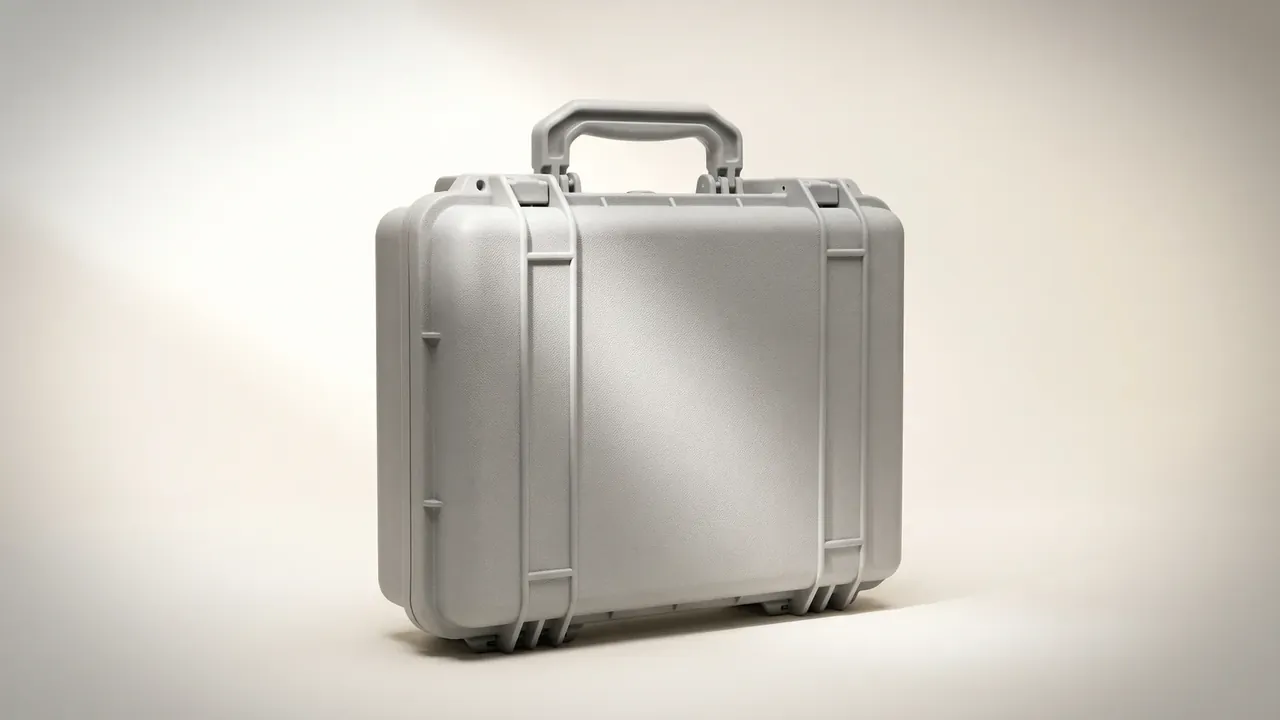
Quick answer: Judge plastic case design and manufacturing by the document package, not the showroom. A usable package ties each structural number to a clause, proves that 3D and 2D agree, answers DFM questions with values and keeps revisions traceable. Without those four, quotations are not comparable.
Table of contents
- The six deliverables in a plastic case design and manufacturing package
- 3D data and 2D drawings have to prove each other
- What a DFM report must answer
- Drop simulation and drawing revision control
- FAQ
1. The six deliverables in a plastic case design and manufacturing package
A quotation saying only build to drawing carries no criteria. What buyers can compare is drawing depth: whether wall thickness, draft, radii and acceptance clauses sit in one controlled file.
| Deliverable | Clause usually cited | Acceptance rule |
|---|---|---|
| 3D model | ISO 10303-242 (STEP AP242) | Matches the 2D sheet, feature tree intact |
| 2D drawing | ISO 2768-m | Critical sizes dimensioned, datum A on the base plane |
| DFM report | Supplier checklist | High-risk items closed with an owner |
| Ingress test | IEC 60529, IP6X and IPX7 | 30 minutes at 1 m depth, no ingress |
| Drop test | MIL-STD-810H method 516.8 | Six faces at 1.2 m, function intact |
| First article report | Full dimensions plus material cert | Zero out-of-tolerance items, resin lot recorded |
IPX7 describes a 1 m, 30 minute immersion and resolves into three coupled features: gasket groove width, gasket compression, latch preload. Method 516.8 frames the drop procedure; height, attitude and criteria belong in the signed specification.
2. 3D data and 2D drawings have to prove each other
The model defines shape; the sheet defines judgement. A package offering IGES only is worth questioning: IGES carries surfaces, loses the feature tree, and one radius change can mean re-stitching.
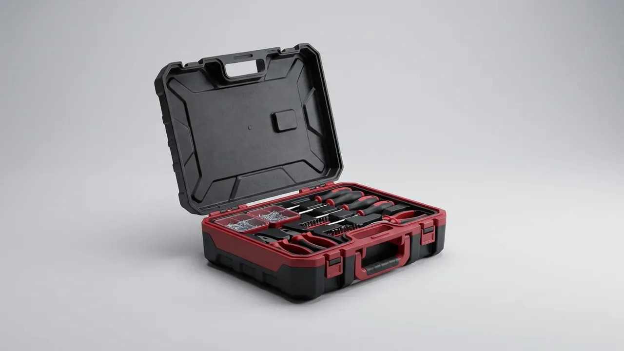
A workable pairing is STEP AP242 plus an A1 sheet with datums. AP242 keeps tolerance and annotation semantics for gauge programming; the sheet sets datum A on the base plane, datums B and C on the side walls, holes at plus or minus 0.2 mm.
Wall thickness in plastic case design and manufacturing follows process: 2.5 to 4 mm for injection moulding against 3.5 to 5 mm for blow moulding. When one shell varies by more than 1.5 times, sink appears behind the thick zone and a 0.2 mm dip shows through texture.
Draft runs 1 to 2 degrees by depth, deep cavities at the upper end; corners sit between R3 and R8, larger outside for drop resistance, smaller inside for space. That plastic case design and manufacturing detail belongs in the title block, where it survives revisions.
3. What a DFM report must answer
The easiest element of plastic case design and manufacturing to fudge is the DFM report. A usable one skips verdicts, answering six questions with numbers:
- Does every wall fall between 2.5 and 4 mm, and what is the thick-to-thin spread
- Are side walls at 1 degree of draft, deep cavities at 2 degrees
- Are corners within R3 to R8, with R0.8 at rib roots
- Where do weld lines land, and do any cross the gasket groove
- Which faces carry ejector marks, at what pin count
- Where will sink appear, were bosses cored to 2.5 mm
Three blanks out of six and the document stops being a review tool.
A solid 6 mm mounting boss sinks 0.1 to 0.15 mm on the face under the gasket, and water finds it. Coring it into a 2.5 mm sleeve removes the sink; pull-out falls from 480 N to 420 N, still above margin.
4. Drop simulation and drawing revision control
Plastic case design and manufacturing reviews do not want animation. A 1.2 m six-face drop needs boundary conditions first: 4.85 m/s impact velocity, rigid floor, payload at 1.2 times the loaded mass, 2 mm mesh.
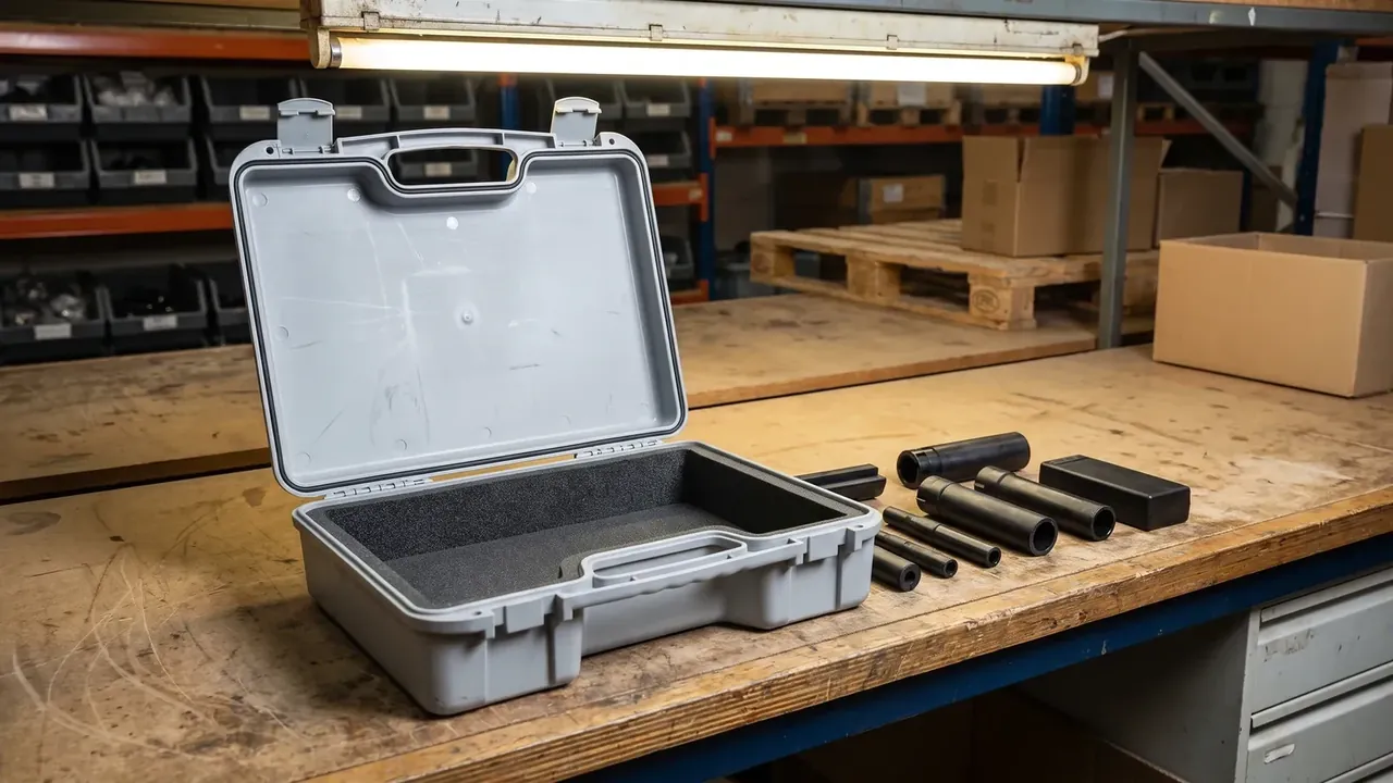
Read three results. Corner peak acceleration above 500 g sustained past 2 ms means the liner needs recalculation. Gasket groove opening beyond 0.6 mm will not hold IPX7. Permanent set over 1.5 mm on the base diagonal costs one stacking tier. If two of the three fail, change structure rather than resin. Simulation is not hardware: the first article takes nine real drops, six faces and three edges, then a 30 minute immersion check.
| Drop attitude | Impact velocity | Limit checked |
|---|---|---|
| Base | 4.85 m/s | Permanent base set under 1.5 mm |
| Corner | 4.85 m/s | Peak acceleration under 500 g |
| Gasket side | 4.85 m/s | Groove opening under 0.6 mm |
Revision control is the other half. Even a radius change earns a new revision, numbered as project, letter and sequence such as 2418-B-03, with a log of old and new values and the effective batch.
The shop floor uses stamped revisions only. That reads like paperwork until a mould runs two revisions and lids arrive 0.8 mm off.
Conclusion
Two suppliers of plastic case design and manufacturing differ in paper before they differ in plastic: an editable model, a datum-based sheet, a DFM report with numbers and revisions that trace. Audit those four and trial shots drop, rework ownership clears, prices become comparable. Ask for the package first, then compare plastic case design and manufacturing quotes on those four items.
This article discusses only the container (case body) side of specifications and design intent, and does not cover any handling, loading or use of the contents.
Related Reading
Related Products
- 8 Series — Gun Cases; Military Equipment Cases; Camera Equipment Cases; Drone Cases; Watch Cases; Knife Cases; First Aid Cases; Electronics Equipment Cases
- WL8-2812 PP Gun Case — model WL8-2812
- All protective cases and toolboxes: 7 series, 158 models