

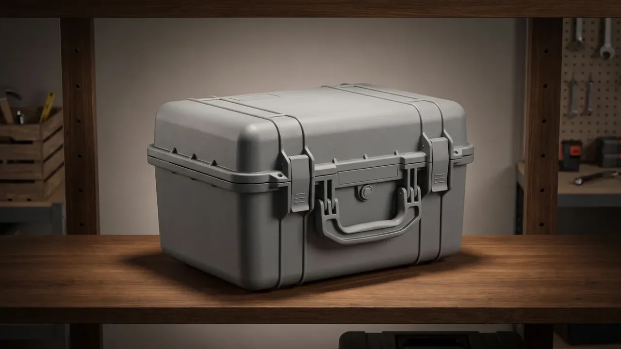
Quick answer: A shockproof engineering equipment case is set by its liner, not its wall: EVA of 65 kg/m³ at 30 mm holds peak acceleration under 45 g on a 6 ms pulse.
Table of contents
- The Drop Curve of a Shockproof Engineering Equipment Case
- EVA Density and Cushion Thickness
- Peak Acceleration and Pulse Width
- Compression Set in the Liner
- Cushion Settings for Engineering Crews
- FAQ
1. The Drop Curve of a Shockproof Engineering Equipment Case
The line a drop rig prints is shaped almost entirely by liner thickness and density; the wall is a supporting player. Time runs on one axis, acceleration on the other, and two readings matter: peak g, pulse ms.
The shape says more than the figures. A single rounded hump means the liner absorbed through the whole compression; a double hump or flat top means it bottomed out and the shell took the hit. A shockproof engineering equipment case is accepted on the first hump alone.
One drop set covers six faces: base, lid, four sides, edges. The base has the largest contact area and the lowest peak; an edge touches a few square centimetres and returns the worst curve.
| Cushion tier | EVA density | Liner thickness | Where it goes |
|---|---|---|---|
| Light load | 45 kg/m³ | 20 mm | Light contents, under a metre |
| General | 65 kg/m³ | 30 mm | Standard equipment, six-face handling |
| Heavy load | 90 kg/m³ | 40 mm | Dense loads, repeated transfers |
The tier is the thinnest layer that still holds the peak below 45 g across six faces; thinner high-density EVA suits local pads only.
2. EVA Density and Cushion Thickness
Inside the liner, density and thickness do different jobs. Density sets the plateau stress the foam settles at once it crushes; thickness sets the travel before it bottoms. At 65 kg/m³ the dynamic cushion curve of EVA peaks between 4 and 6 psi, which covers the floor pressure of a 7.2 kg unit.
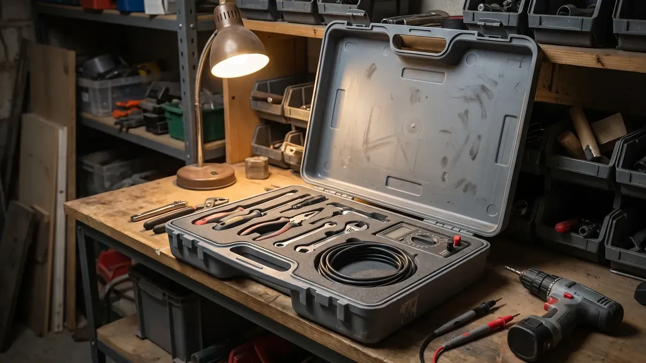
The EVA inside a shockproof engineering equipment case is closed cell, pores of 0.2 to 0.5 mm and densities of 45 to 250 kg/m³. Fine pores buckle and recover evenly; a coarse batch gives a serrated curve, three drops and three peaks.
The 30 mm is split in two. The base takes vertical impact at full thickness, while the sides resist edge landings and only the corner section compresses; the sides drop to 20 mm, returning space to the 550 × 390 × 215 mm cavity.
Higher density is not better in a shockproof engineering equipment case. At 90 kg/m³ the foam barely moves under light load, so energy travels through it into the shell and the peak climbs. The heavy tier runs 40 mm for longer travel, not for the density itself.
3. Peak Acceleration and Pulse Width
At 1.2 m with one drop per face, the criterion is 45 g or less at the peak and 6 ms or more of pulse. That pair sits near the upper edge of the MIL-STD-810H shock method, Procedure I, at 20 to 40 g over 6 to 11 ms, and the margin covers liner ageing.
In a shockproof engineering equipment case the peak and the pulse width move opposite ways: at one drop height a softer liner compresses further, acceleration rises more slowly, the pulse widens and the peak falls. Their product tracks the velocity change, which the height fixes.
| Drop round | Landing point | What to watch | Criterion |
|---|---|---|---|
| Round 1 | Base and lid | Whether the face bottoms out | Peak ≤45 g, no flat top |
| Round 2 | Four sides | Whether side pads shift | Peak ≤45 g, pads seated |
| Round 3 | Four edges | Load shared by corner posts | Peak ≤45 g, no through crack |
The edges are the hard ones. Corner foam is squeezed from three directions, less than half its volume is free to compress, and the contact area is the smallest of any attitude. The shockproof engineering equipment case puts a φ22 mm post in each corner to spend the first part of the travel before the broad liner joins.
4. Compression Set in the Liner
Reuse comes down to compression set: compress the foam for 22 h at 40 ℃, release it, and the thickness that does not return is the set. The limit is 8%, while 65 kg/m³ EVA typically lands at 3% to 5%.
Resilience of 42% is a separate reading: how fast the foam springs back, which is not set. A liner with low resilience has not reset between two drops, so the second drop gets shorter travel and a higher peak.
Loading cycles eat thickness too. After 20 insertions a 30 mm liner collapses 1 to 2 mm at the cut edges, and the collapsed edge lets equipment rock, turning the gap into fresh travel.
5. Cushion Settings for Engineering Crews
Field readings for a shockproof engineering equipment case come from a portable recorder clipped to the base, sampling at 10 kHz. Read the first peak only; later ones come from rebound and secondary landings.
| Peak reading | Curve shape | Action |
|---|---|---|
| ≤45 g | Single rounded hump | Keep in service, retest quarterly |
| 45 to 60 g | Double hump or slight flat top | Add thickness or cut the load |
| >60 g | Flat, saturated top | Withdraw, replace liner, retest |
The 4.8 mm shell absorbs nothing; it holds cavity dimensions, resists puncture and passes force into the corner posts. At 7.2 kg stacked 4 high, the bottom lid carries about 21.6 kg through its ribs.
The 4,300-cycle and IP67 figures mark the use side. Near cycle 4,300 the hinges feel stiff and gasket compression starts to fall; IP67 covers short immersion only, so a dropped case is re-tested, since a corner crack is rarely visible.
Conclusion
The cushioning of a shockproof engineering equipment case is set by 65 kg/m³ of EVA at 30 mm plus four φ22 mm posts, then accepted on two readings from a 1.2 m six-face drop: 45 g and 6 ms. A 4.8 mm wall and 7.2 kg weight are givens; 4-high stacking and 4,300 cycles mark the use side. Hold set under 8% and it earns the next drop.
Related Reading
Related Products
- 8 Series — Gun Cases; Military Equipment Cases; Camera Equipment Cases; Drone Cases; Watch Cases; Knife Cases; First Aid Cases; Electronics Equipment Cases
- WL8-2812 PP Gun Case — model WL8-2812
- All protective cases and toolboxes: 7 series, 158 models