

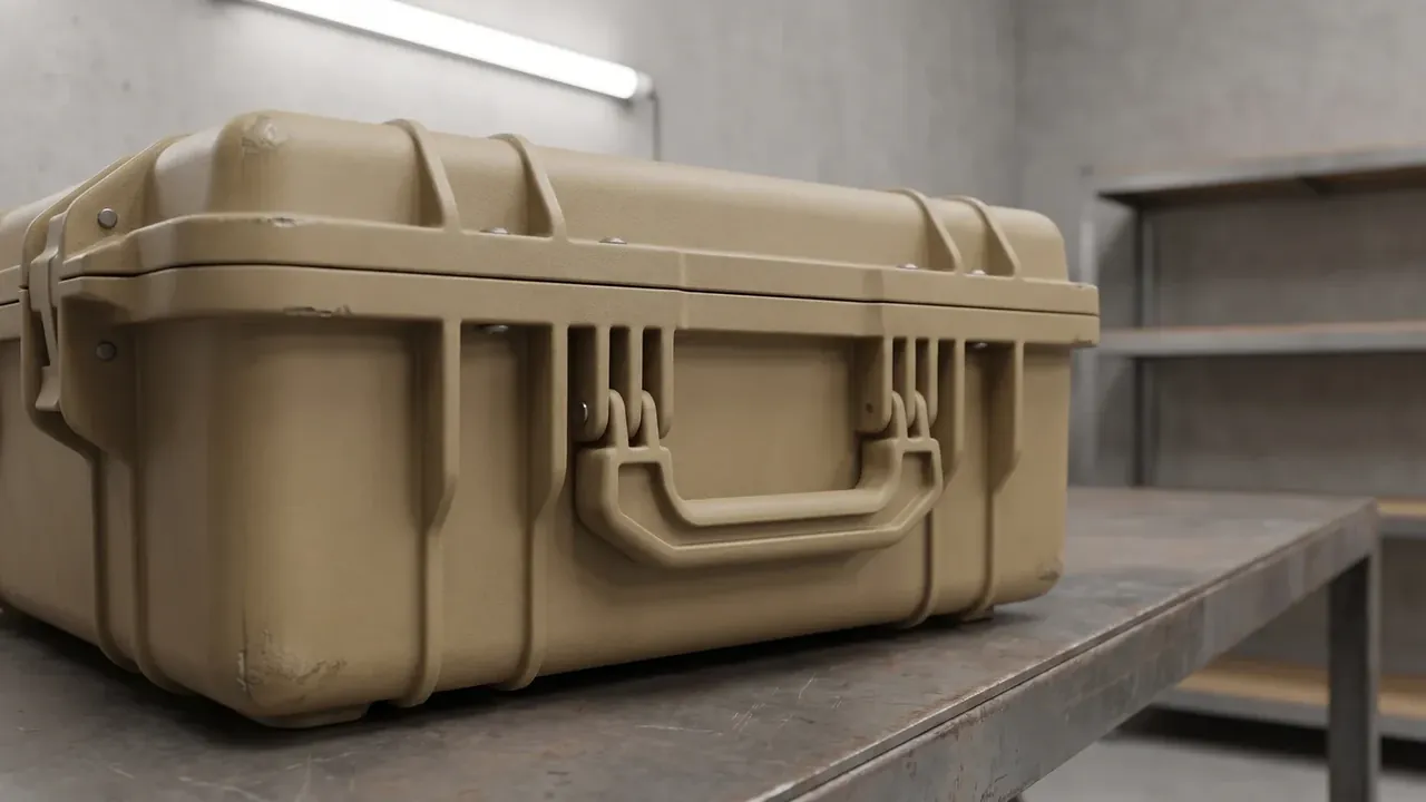
Quick answer: An Airdrop Case is read in five places: how the cushion absorbs energy, how the shell joins the frame, where lifting points sit, how latches resist release, and how corners are reinforced. Together they decide whether impact is carried as one body or shed layer by layer.
Table of contents
- How an Airdrop Case Absorbs Impact
- Joining the Shell to the Frame
- Where Lifting and Tie-Down Points Sit
- Latches and Anti-Release Design
- Landing Attitude and Corner Reinforcement
- FAQ
1. How an Airdrop Case Absorbs Impact
An Airdrop Case does not cushion with one slab of foam. It works in three stages: a shell that resists puncture and spreads point loads, a middle layer that stretches the deceleration distance, and a liner that locates. At an impact speed of 8 m/s, a 20 mm stroke peaks near 120 g; at 60 mm it falls to about 45 g.
| Layer | Common material | Reference thickness | Function |
|---|---|---|---|
| Shell | Rotomoulded PE or modified PP | 4.5 mm | Puncture resistance, spreading |
| Cushion | EVA foam, expanded PE | 30 to 60 mm | Stroke, energy absorption |
| Frame | 6061-T6 aluminium tube | 20 × 20 × 2 mm | Shape retention, load path |
| Liner | Low-density EVA or sponge | 10 to 15 mm | Location and wear |
Material follows the temperature band. EVA at 45 kg/m³ holds its rebound but stiffens at -40°C, losing about 30 percent of its cushioning; expanded PE stays flatter in the cold but absorbs 20 percent less at equal thickness. Cold-climate cases stack the two, and closed-cell content below 85 percent lets the cushion collapse, so the second impact peaks 25 percent higher.
2. Joining the Shell to the Frame
Shell and frame are two materials with two stiffness values, so the joint fails first. The usual route is an M8 insert moulded into a 4.5 mm PE wall, a 6061-T6 tube frame at 2 mm, and bolts torqued to 12 N·m.
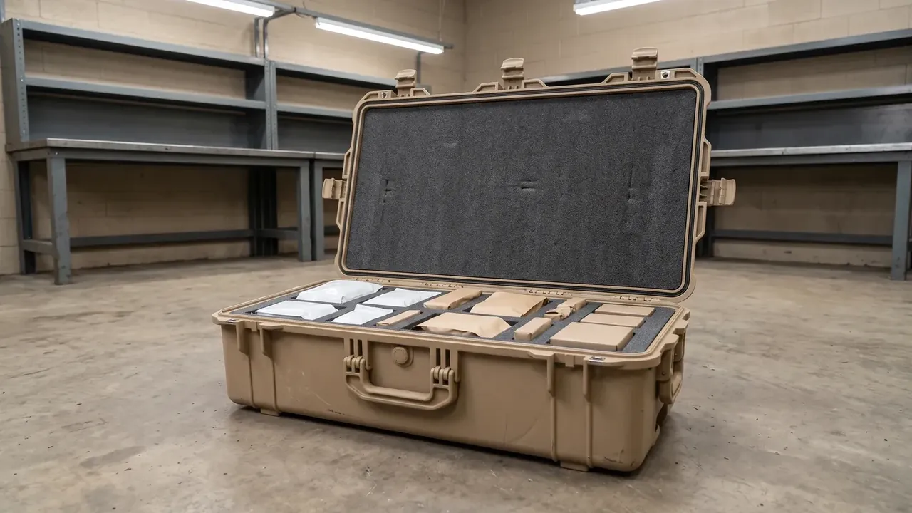
Pull-out strength is the hard number: an M8 insert should hold 3 kN at room temperature, and a wider flange at the base does more than a bigger bolt. A 2 mm nylon washer between frame and skin stops metal grinding into plastic. Hinges run three across at 300 mm centres.
3. Where Lifting and Tie-Down Points Sit
Lifting points decide how load leaves the body, so position beats count. Four points sit either side of the centre of gravity at 2.5 kN each, with a factor of three.
They do not belong on a radius, where stress concentration exceeds 2.5 and more than doubles the local stress; points sit on flat faces at least 25 mm away, backed by a 3 mm steel plate. Six tie-down rings at 25 mm webbing stay near the lower frame nodes.
4. Latches and Anti-Release Design
Latches must stay shut under impact and still open one-handed. The answer is a two-point latch with a safety pin, a PA66 body at 30 percent glass fill, 8 mm travel and about 120 N opening force.
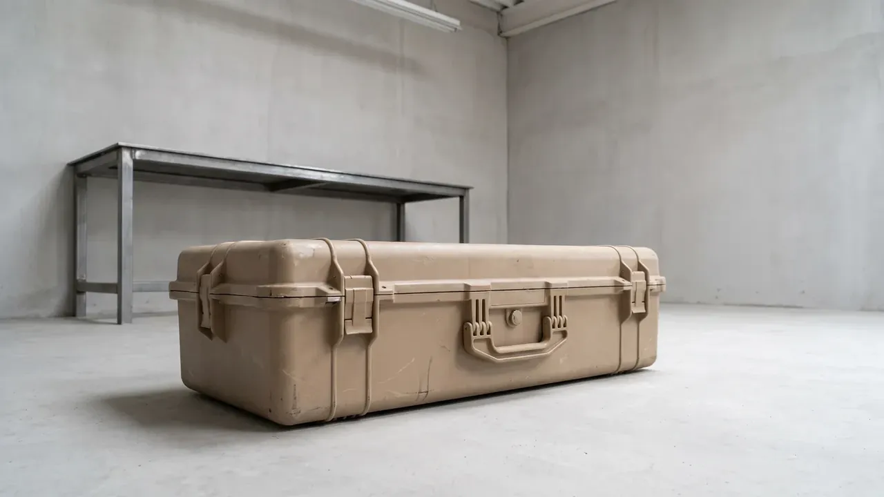
Anti-release comes from a second motion, not a stiffer spring: the pin slides sideways before the latch lifts. The check is a 2-hour sweep from 10 to 500 Hz plus a 1.2 m drop on six faces. Pivot pins go stainless, since glass-filled nylon keeps half its impact strength at -40°C.
5. Landing Attitude and Corner Reinforcement
Attitude at impact follows from centre of gravity and floor shape. Keeping the centre within 40 percent of case height, on two longitudinal skids, makes the long edges land before any single corner.
| Zone | Reinforcement | Size | What to watch |
|---|---|---|---|
| Corners | Replaceable cap | 8 mm wall, R25 | Cap fit, screws recessed |
| Base | Longitudinal skids | 12 mm high, 30 mm wide | Skid wear |
| Lid | Transverse ribs | 120 mm pitch | No sink marks at rib roots |
Corner caps are separate: 0.6 kg across four corners instead of weight everywhere, swapped when worn. Lid ribs at 120 mm pitch need a generous wall transition at the root, or a sink mark drops the wall from 4.5 mm to 3.2 mm and the whole Airdrop Case is thinnest along its lid.
Conclusion
The structure of an Airdrop Case is a load path from outside in: shell spreads, cushion stretches the stroke, frame holds shape, latches hold closure, corners take the first contact. Once stroke, torque, pull-out, opening force and wall thickness are fixed, the structure closes, and that is where Airdrop Case reliability comes from.
This article discusses only the container (case body) side of specifications and design intent, and does not cover any handling, loading or use of the contents.
Related Reading
- Inspection items and acceptance
- How the case differs from alternatives
- Cushion design in shockproof cases
- Standards for military air transport cases
Related Products
- 8 Series — Gun Cases; Military Equipment Cases; Camera Equipment Cases; Drone Cases; Watch Cases; Knife Cases; First Aid Cases; Electronics Equipment Cases
- WL8-2812 PP Gun Case — model WL8-2812
- All protective cases and toolboxes: 7 series, 158 models