

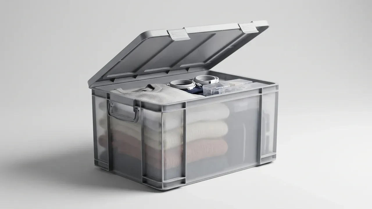
Quick answer: A cartridge transport box earns its life in the load path, not in a wall-thickness figure: corners steer impact away from edges, inserts spread point loads, and gaskets only seal when latches press evenly.
Table of contents
- Why the Cartridge Transport Box Frame Starts With Impact
- Fixing and Cushioning: How the Insert Takes the Load
- Sealing and Water Management Beyond the Gasket
- Latches, Hinges and Anti-Tamper Details
- Fork, Lifting and Marking Interfaces
- FAQ
1. Why the Cartridge Transport Box Frame Starts With Impact
A storage case meets static load; a cartridge transport box meets a load spectrum. Every lift is a burst of acceleration; road joints add vibration.
A 1.2 m drop onto six faces and eight corners asks whether the latch still bites. Energy concentrates at the tightest radius, so corners get a double radius and radial ribs.
| Zone | Process | Load | Field check |
|---|---|---|---|
| Wall | 3.2 mm, vertical ribs | Stacking, knocks | Springs back |
| Corner | Double radius, 6 ribs | Corner drop | No white cracks |
| Base | Grid on four feet | Fork lift | Stays flat |
Injection moulding holds a 3.0–4.0 mm wall and ±0.3 mm tolerance, so latch mounts carry insert holes.
2. Fixing and Cushioning: How the Insert Takes the Load
An insert does two jobs. Location holds an item through the cavity surface; cushioning stretches impact over longer travel, lowering peak acceleration at the cost of volume.
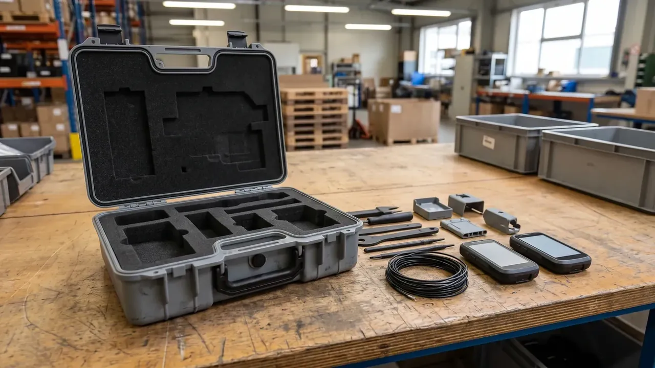
| Insert type | Cushion travel | Location | Changeover |
|---|---|---|---|
| Solid EVA, routed | 8–10 mm | Cavity wrap | New cutting die |
| Laminated EPE | 12–15 mm | Pressed layers | New slice |
| Moulded tray | 3–4 mm | Clips and walls | Swap tray |
Clearance causes more failures than material grade: 0.5 mm larger per side loads without rattle, below 0.3 mm foam loses rebound.
3. Sealing and Water Management Beyond the Gasket
Sealing is a clamping system, not a strip of rubber. The groove runs 1.2 times the cord diameter, the cord is commonly 7 mm, and compressed height should land between 25 and 35 percent.
Clamping force follows latch spacing. Past 300 mm between latches the lid crowns and water enters at the high point. Holding 250–300 mm with one midpoint clamp fixes most of it, and a pressure-equalisation valve stops the lid sucking down in wide swings.
4. Latches, Hinges and Anti-Tamper Details
Latches are the most underrated parts on a cartridge transport box. Spring draw latches clamp through travel, cam latches self-lock, and threaded knobs rely on preload. Springs fatigue, cams wear, and knobs back off until half the clamp force is gone.
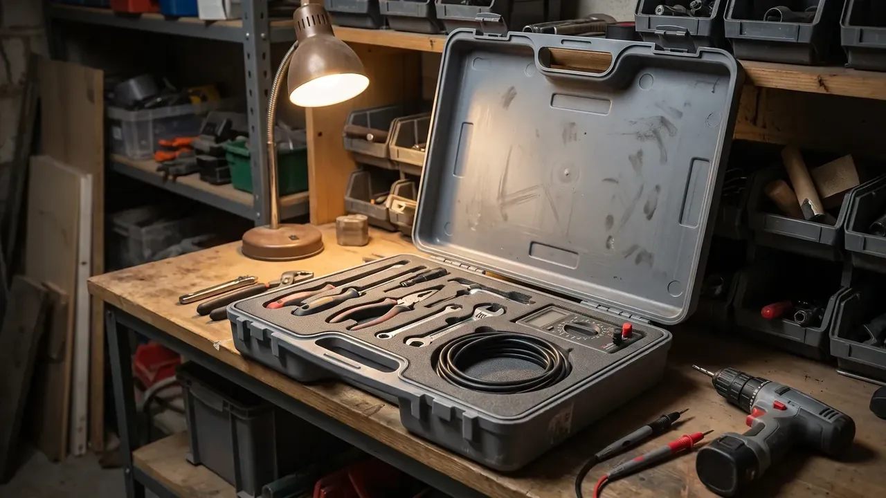
| Latch type | Holding force | Strength | Failure |
|---|---|---|---|
| Spring draw latch | 350–500 N | One-hand opening | Spring fatigue |
| Cam latch | 400–600 N | Self-locking | Cam face wears |
| Threaded knob | Set by preload | Adjustable clamp | Backs off |
Hinges set service life: a 5 mm 304 stainless pin in a nylon bush resists shear, and a hinge that holds lid alignment after 20,000 cycles sits on two bosses. A 3 mm seal-wire hole leaves a checkable trace.
5. Fork, Lifting and Marking Interfaces
The biggest difference from a storage case: a machine must be able to grab this box. Fork pockets are not two holes in a wall: 75 mm high, 200 mm deep, with a 4 mm flange.
| Interface | Position | Size or rating | Failure |
|---|---|---|---|
| Fork pocket | Base sides | 75 mm high, 200 mm deep | Flange cracks |
| Lifting eye | Four lid corners | 400 kg each | Insert pulls out |
| Marking plate | Recessed end face | 120 × 80 mm | Falls out, fades |
Lifting points are stricter: eyes rated 400 kg each derate at a 45 degree angle to seventy percent, and inserts must sit in solid wall. Marking sits in a 120 × 80 mm recess on the end face.
Conclusion
The cartridge transport box is a system of restraints: corners divert impact, inserts flatten loads, gaskets depend on even latch pressure, and fork pockets must land on structural nodes. Read the five interfaces together and you judge service life better than by wall thickness, which separates a real cartridge transport box from a look-alike.
This article discusses only the container (case body) side of specifications and design intent, and does not cover any handling, loading or use of the contents.
Related Reading
- Capacity calculation and loading efficiency for cartridge transport boxes
- Transport packaging requirements a cartridge transport box must meet
- How foam inserts are formed and how cavities are designed
- Sealing grades and test methods for waterproof hard cases
Related Products
- 8 Series — Gun Cases; Military Equipment Cases; Camera Equipment Cases; Drone Cases; Watch Cases; Knife Cases; First Aid Cases; Electronics Equipment Cases
- WL8-2812 PP Gun Case — model WL8-2812
- All protective cases and toolboxes: 7 series, 158 models