

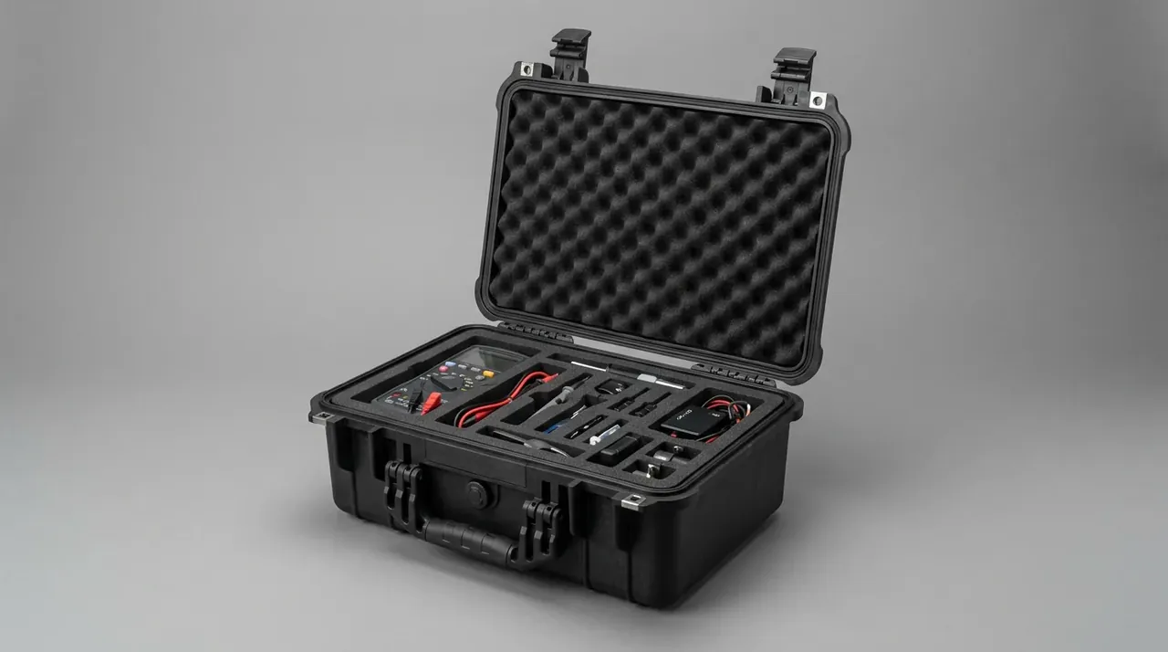
Quick answer: Case handle position should follow the two-person grip height, with the handle top 700 to 760 mm above the floor and both sides level within 10 mm.
Table of contents
- Handle Height Reference for a Two-Person Lift
- Handle Spacing and the Load Split per Side
- Sidewall Reinforcement Around the Handle Root
- Lift Angle and Lower-Back Load
- Matching Handle Height to Case Weight
- Drawing Callouts and Acceptance
- FAQ
1. Handle Height Reference for a Two-Person Lift
Dropping the handle top from 780 mm to 680 mm on a 28 kg case raises L5/S1 compression about 15% and adds about 9 N·m to the lumbar moment. The case got no heavier; the lever did: every 5° of trunk lean adds 20 mm between lower back and grip.
Knuckle height is the measurable reference: an operator 1.70 m tall stands with knuckles near 720 mm, so a handle top of 700 mm to 760 mm keeps the wrist neutral and the elbow at 100° to 120°.
Case height eats into it. A 400 mm sidewall puts the handle 300 mm to 340 mm above the base, leaving 80 mm to 120 mm of clearance. On a 210 mm shell the handle meets the lid lip, so change the grip, not the height.
2. Handle Spacing and the Load Split per Side
Two handles off one level line load the low side first. On a 28 kg case with 15 mm difference, the low side carries 16.2 kg against 11.8 kg, a 37% split.
Spacing for side-by-side carrying belongs between 400 mm and 600 mm. Below 350 mm the case swings 6° to 8° about its centre line. Above 650 mm the outer hand reaches past the shoulder line and abduction passes 45°, so grip stability drops.
Face-to-face carrying is governed by the centre of gravity, not spacing: a centre 20 mm off the middle adds 8% to 12% on the heavy side, 40 mm adds 18%. Past 150 mm of vertical offset the case drops 20 mm to 30 mm at lift-off and the grip takes a 1.4 times static shock.
3. Sidewall Reinforcement Around the Handle Root
The handle hands a concentrated load to the sidewall, which spreads it into the shell. With 2.5 mm of wall inside an 80 mm radius of the root, a 28 kg lift reaches 9 MPa, the yield floor for PP at 40 ℃.
Copy the numbers: one vertical rib above and one below the root, 3.5 mm thick, 6 mm proud of the inner wall, from base to 60 mm past the mounting face, spaced 0.8 times handle width. Tighter spacing leaves sink marks, and a sink past 0.4 mm disturbs the seal face.
Keep ribs off the screw bosses, with 8 mm from boss centre to rib root. Under 6 mm the root splits at assembly torque and the crack runs 15 mm to 25 mm. An R2 fillet carries 15% more load than a sharp corner.
4. Lift Angle and Lower-Back Load
Lift angle is the angle between case base and floor. In a synchronised lift it stays under 15°. When one side leads it passes 25°, the trailing wrist dorsiflexes 30°, and the load slides forward 40 mm to 60 mm.
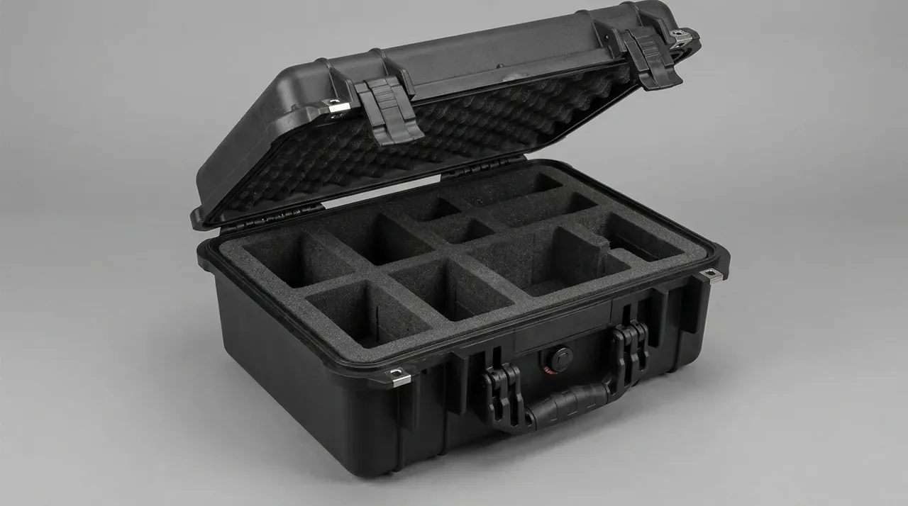
A handle within 50 mm of the centre of gravity keeps the case steady but leaves fingers only 30 mm to 40 mm above the base. More than 150 mm above the centre of gravity, the case oscillates 4° to 6° while suspended, and the swing doubles once rhythm breaks.
Lower-back load follows the angle. Each 10° adds 6° to 8° of trunk lean, and 8° of lean adds 12% to the lumbar moment. At 28 kg and 25° the leading side sees 78 N·m; at 10°, 56 N·m. A shared count cuts the start gap to 0.15 s.
5. Matching Handle Height to Case Weight
Weight sets how high the handle sits and how much angle two people can take. Ranges assume a synchronised lift of 10 m or less; longer carries want the handle 20 mm to 30 mm lower.
| Case weight | Handle top above floor | Handle spacing | Load per side | Lift angle limit |
|---|---|---|---|---|
| 12 kg | 720 mm to 760 mm | 380 mm to 450 mm | 6.0 kg to 6.4 kg | 18° |
| 18 kg | 700 mm to 750 mm | 420 mm to 520 mm | 8.8 kg to 9.5 kg | 15° |
| 24 kg | 690 mm to 740 mm | 450 mm to 560 mm | 11.4 kg to 12.4 kg | 12° |
| 28 kg | 680 mm to 730 mm | 480 mm to 600 mm | 13.2 kg to 14.6 kg | 10° |
| 34 kg | 660 mm to 710 mm | 500 mm to 620 mm | 15.8 kg to 17.6 kg | 8° |
Read it one way: each weight step moves the handle down 10 mm to 20 mm and tightens the angle limit by 2° to 3°. At 34 kg, 660 mm to 710 mm with 500 mm to 620 mm spacing holds each side at 15.8 kg to 17.6 kg. A section narrower than 32 mm lifts palm pressure from 0.18 MPa to 0.26 MPa.
6. Drawing Callouts and Acceptance
Three dimension groups cover the drawing: handle top to base, coplanarity of the centrelines, and root rib position with height. All run from the base datum, never the lid lip, which carries 0.5 mm to 1.2 mm of moulding variation.
| Acceptance item | Limit | Method |
|---|---|---|
| Height difference between handle tops | ≤ 10 mm | Surface plate and height gauge |
| Handle centre to centre of gravity | ≤ 120 mm | Weigh for centre of gravity |
| Root rib height | 6 mm ± 0.5 mm | Depth gauge on inner wall |
| Boss centre to rib root clearance | ≥ 8 mm | Calipers |
| Wall thickness within 80 mm of root | ≥ 3.0 mm | Ultrasonic, mean of 5 points |
| Displacement after 200 empty lifts | ≤ 0.6 mm | Scribed line and feeler gauge |
Acceptance runs after assembly: after 200 empty lifts, displacement past 0.6 mm means the rib root has yielded, about three months before a visible crack.
Conclusion
Handle position is a coordinate for load, not a styling dimension. Set the handle top at 700 mm to 760 mm for the people who will carry it, pull spacing to 480 mm to 600 mm for the actual weight, then confirm the handle sits within 120 mm of the centre of gravity. Only then do the two 3.5 mm ribs at the root mean anything: ribs that miss the load path spread nothing. Draw the ribs first and they land 30 mm off, enough to push local stress back past 9 MPa. Any change to case handle position has to move the ribs with it, and those two dimensions belong in one callout.
This article discusses container-side specifications and design implications only, and does not cover any handling, loading or use of the contents.
Related Reading
- Static and dynamic load testing for handles
- How reinforcement ribs are laid out
- Wall thickness and load capacity
Related Products
- 8 Series — Gun Cases; Military Equipment Cases; Camera Equipment Cases; Drone Cases; Watch Cases; Knife Cases; First Aid Cases; Electronics Equipment Cases
- WL8-2812 PP Gun Case — model WL8-2812
- All protective cases and toolboxes: 7 series, 158 models