


Quick answer: A Case Mould is specced backwards from a 1200 mm cavity and a 42 kg load, which set an 8 mm base and a 6 mm wall; the seal groove chain then pins tolerance to one side.
Table of contents
- Deriving a Case Mould Spec from a Blank Drawing
- Load Paths Set the Wall Thickness
- Split Line and Draft Decide Where Tolerance Sits
- The Dimension Chain of Latches Hinges and Seal Groove
- What Three Trials Changed in the Spec
- FAQ
1. Deriving a Case Mould Spec from a Blank Drawing
The sample job carried three lines: a cavity of 1200 by 480 by 220 mm, a 42 kg load and two-high stacking. The wall thickness column was left empty.
Wall thickness is not a guess: the load path and the dimension chain squeeze it from both ends. Area first, wall last.
| Input | Intermediate | Drawing value |
|---|---|---|
| Cavity 1200 x 480 x 220 mm | Projected area, stack weight | 8 mm base |
| 42 kg, stacked two high | Side edge load, bulge | 6 mm wall |
| 1.2 m drop, corner first | Corner shear, rib root | R12, R2 at root |
| 5000 hinge cycles | Boss bearing | 10 mm seat |
| Service -20 to 55 C | Shrink per 100 mm | 0.6 mm |
2. Load Paths Set the Wall Thickness
This Case Mould runs three gauges: 8 mm base, 6 mm sides, 10 mm hinge seat. The base carries 42 kg over a 480 mm panel and bends; the sides take the edge load of a stacked case; the hinge seat holds eight screws and would strip near cycle five thousand.
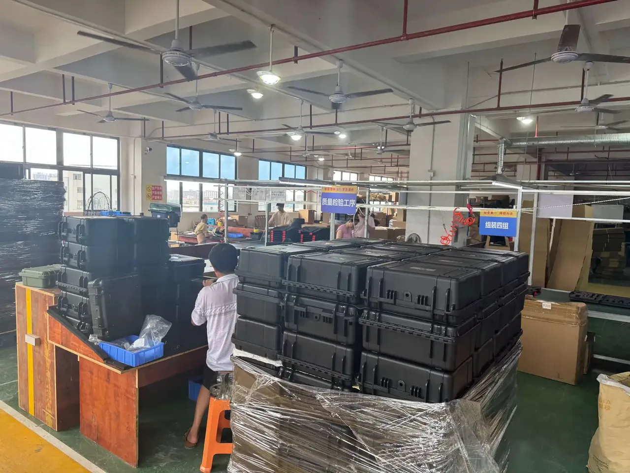
Ribs let this Case Mould save material without collapsing. They run the outer face at 4 by 12 mm, first 90 mm above the base, then every 90 mm, three in total. They cross all four corners with an R2 blend, so stress does not pile at the root. Height stops at 12 mm, since taller ribs foul the feet of the case above. Width stops at 4 mm, the moulding floor: thinner will not fill, thicker sinks the face. Three ribs cut the unsupported 220 mm span into four bands and pull bulge from 3 mm to 0.6 mm.
3. Split Line and Draft Decide Where Tolerance Sits
The split line sits on the largest projected outline, the lip below the case mouth, so flash lands on the outer edge and faces inward. Move it to the base and flash sits under the case.
Draft is set per feature, never as one blanket angle:
- Main side faces: 1.5 degrees, enough to release
- Deep cavity floor: 0.8 degrees, since a 220 mm draw grabs below that
- Rib flanks: 0.5 degrees, with ejector pins taking the rest
- Corners: R12 outside against R6 inside
- Split line flash: 0.1 mm to the outside only
Tolerance is not spread evenly: the outer profile a buyer sees gets plus or minus 0.4 mm, the cavity plus or minus 0.25 mm, and every datum runs off the split line.
Draft is a release minimum, not a comfort setting.
4. The Dimension Chain of Latches Hinges and Seal Groove
The chain starts at the seal groove: 6 mm wide, 4 mm deep, taking a 5 mm O-ring so compression lands between 22 and 25 percent; groove bottom to mouth is 12 mm.
| Link | Nominal | Own tolerance | Total |
|---|---|---|---|
| Groove depth | 4 mm | 0.05 | 0.05 |
| Lid boss | 3.2 mm | 0.06 | 0.11 |
| O-ring cord | 5 mm | 0.08 | 0.19 |
| Latch travel | 2.6 mm | 0.10 | 0.29 |
| Hinge clearance | 0.15 mm | 0.06 | 0.35 |
At plus or minus 0.35 mm the latches still have margin; one more link and they will not pull. Four latches at 180 N give 720 N. A long chain cannot be rescued at the end: groove first, latches second, hinge last.
5. What Three Trials Changed in the Spec
Trial one produced 1.8 mm of base warp, enough to slide paper under a corner. An 8 mm base cooled unevenly on a 650 tonne press at 60 C for 32 seconds, and shrink bowed the face. Radial and ring ribs with a 2.5 mm root brought warp to 0.7 mm.
Trial two failed at the latch: 240 N against an 180 N target. Travel was set at 1.8 mm, 0.8 under drawing, because the lid boss ran to the top of its band; dropping it 0.1 mm returned 190 N.
Trial three leaked at 0.3 bar within 30 seconds, at 18 percent O-ring compression. Deepening the groove to 4.3 mm lifted compression to 23 percent and the retest held.
All three fixes went onto the drawing and the gauge list. A fix that lives only in conversation returns with the next Case Mould.
Conclusion
The spec of this Case Mould is a chain, not a list: cavity and load set projected area, load paths set an 8 mm base, a 6 mm side and a 10 mm seat, and the groove chain pushes tolerance to one side. Each trial only asked which link had gone slack. When the chain closes, a Case Mould drawing is worth signing.
This article discusses only the container (case body) side of specifications and design intent, and does not cover any handling, loading or use of the contents.
Related Reading
- Storing a case mould: rust, lifting and records
- First shot and packing pressure in a trial run
- Split line and water line upkeep intervals
- How shockproof case wall and foam specs are set
Related Products
- 8 Series — Gun Cases; Military Equipment Cases; Camera Equipment Cases; Drone Cases; Watch Cases; Knife Cases; First Aid Cases; Electronics Equipment Cases
- WL8-2812 PP Gun Case — model WL8-2812
- All protective cases and toolboxes: 7 series, 158 models