

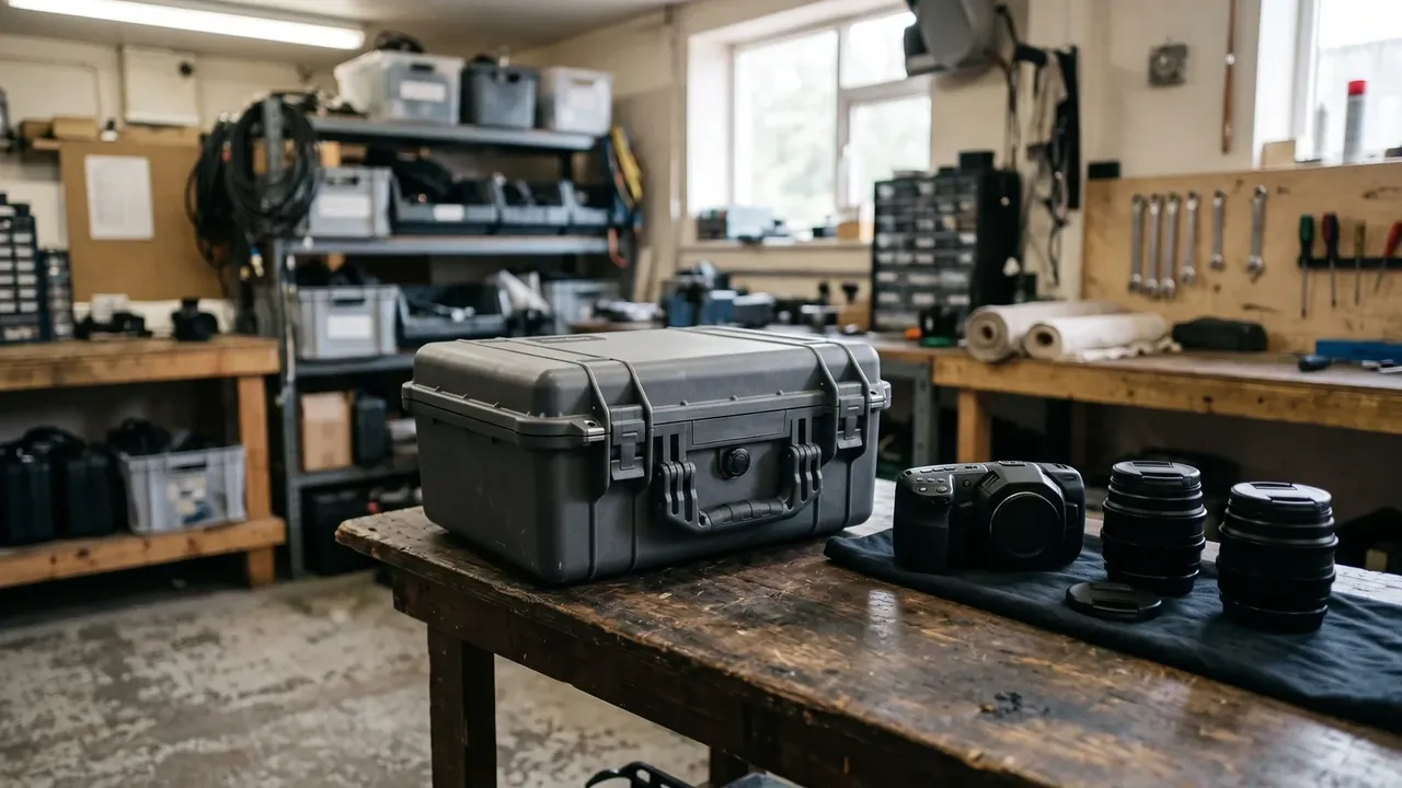
Quick answer: Five parts decide a communication equipment case: shell layers, liner, moulding route, seal and valve, hardware fit. Saving on any one surfaces in transit or on site.
Table of contents
- Five structural layers of a communication equipment case
- Liner and zoning: foam, dividers and device bays
- Moulding the body: rotational, injection and wall thickness
- Sealing, pressure equalisation and transport fixing
- Hardware and assembly tolerance
- FAQ
1. Five structural layers of a communication equipment case
Cut a communication equipment case open and five layers show: shell, ribs, lip, gasket groove, liner. Drop one and the other four carry its job at the weakest point.
The shell takes impact and water. A rotomoulded body runs a 4.5 mm main wall, thickening to 6 mm at the corners where powder collects. Ribs hold stiffness at a pitch of 80 to 120 mm and a height of 6 to 8 mm.
| Layer | Problem solved | Usual practice |
|---|---|---|
| Shell | impact, rain, dust | 4.5 mm wall, 6 mm corners |
| Ribs | panel bulge | 80 to 120 mm pitch |
| Lip | water stop, shear | stepped seat, 1.5 mm gap |
| Gasket groove | squeeze | 8 mm wide, 6 mm deep |
| Liner | location, cushioning | foam, dividers, tray |
The liner touches the equipment and alone decides how many pieces fit.
2. Liner and zoning: foam, dividers and device bays
Most lids carry 20 mm egg-crate foam, not to clamp the load but to preload it lightly so equipment does not chatter.
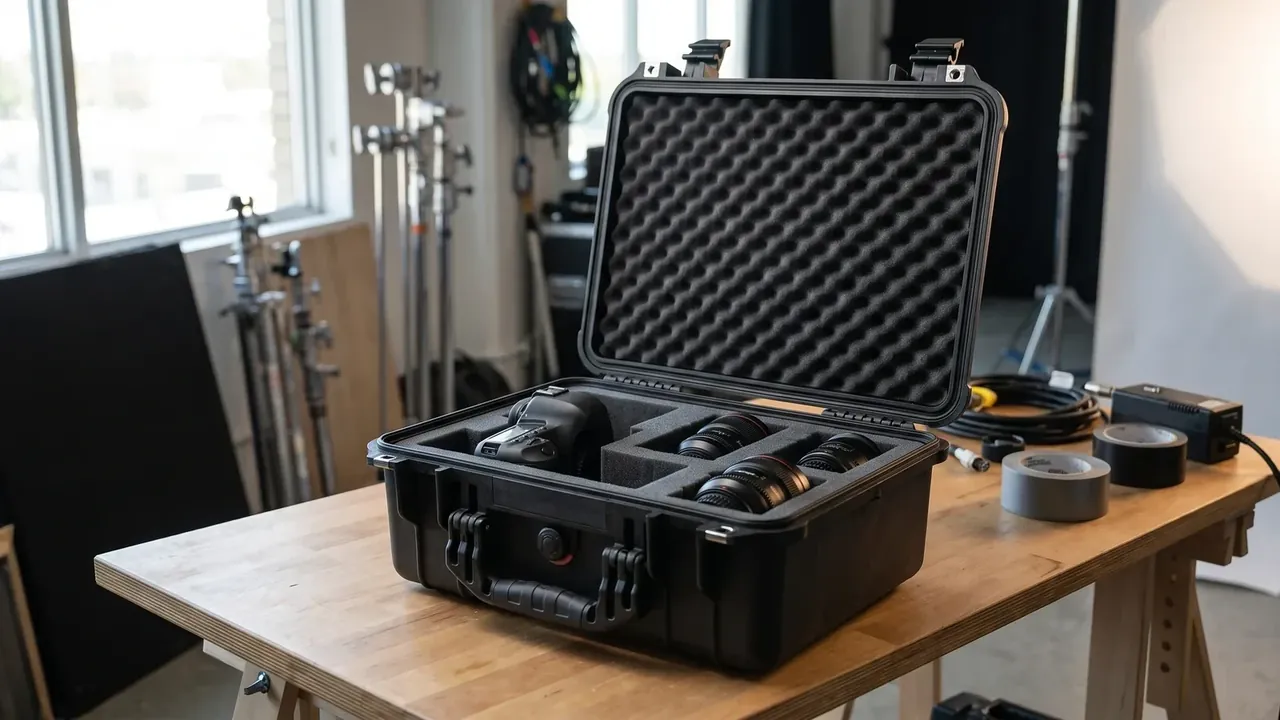
Zoning follows the equipment list. Handsets and batteries may share a bay; a radio module and its supply should not, since supply heat softens the neighbouring foam. Slots run 2 mm shallower than the device so compression holds it. Dividers of 5 mm polypropylene sit in moulded wall slots, so a changed list means new spacing, not a new foam block.
3. Moulding the body: rotational, injection and wall thickness
Rotomoulding tumbles powder in a sheet-steel mould at about 280 °C for 25 minutes, wall thickness set by charge weight. Injection fills a steel tool in tens of seconds.
Rotomoulding suits large, thick parts: past a metre, clamp force turns uneconomic, and thick corners dent rather than split, at 20 percent more weight. Injection suits precision and rate, though flow limits a 3 mm main wall.
| Route | Main wall | Cycle | Best for |
|---|---|---|---|
| Rotational | 4.5 to 6 mm | 25 to 40 minutes | large, low volume |
| Injection | 2.5 to 3 mm | 30 to 90 seconds | small, high volume |
A few hundred units above 800 mm point to rotomoulding; tens of thousands under 600 mm pay back a steel tool.
4. Sealing, pressure equalisation and transport fixing
Gaskets are EPDM at about 60 Shore A and work by compression: 30 percent squeeze rebounds best, and past half the rubber takes a set. Groove depth and cord diameter must match.

Pressure differential is the overlooked item. In flight the outside pressure falls, the lid is sucked down and the latches release without it lifting. A valve vents near 15 kPa; without one the only way in is prying the lip.
Never tie down by the handle alone. A strap there pulls off the centre of gravity, so the case leans under braking; two 8 mm holes let webbing cross the base to a rail and hold movement to a few millimetres.
5. Hardware and assembly tolerance
Draw latches hold around 350 N. Below 200 N a loaded drop pops them; above 350 N the hook bends before it releases.
Hinges are sized by cycles: a field case opens a dozen times a day, about 4,000 a year, so 5,000 cycles leaves margin, with 0.1 mm pin clearance.
| Part | Reference | Check |
|---|---|---|
| Draw latch | 350 N | pull with a gauge |
| Hinge | 5,000 cycles | measure pin clearance |
| Handle | 25 kg static | hang a load ten minutes |
| Screw | 1.2 N·m | torque-wrench sample |
| Joint gap | 1.5 mm | feeler gauge at the lip |
A 1.5 mm gap per side closes cleanly; under 1 mm paint or grit jams the lid, and over 3 mm the latch drags it down. Trial-fit hardware first.
Conclusion
Layers set water and impact resistance, the liner sets location, the moulding route sets wall and weight, the seal and valve set how the lid opens, the hardware sets life. Work through them in order, because a communication equipment case is only as strong as its weakest layer.
This article discusses only the container (case body) side of specifications and design intent, and does not cover any handling, loading or use of the contents.
Related Reading
- Choosing a communication equipment case: shielding, heat and cabling
- How rotational moulding sets case wall thickness
- Laying out internal dividers and liners
- Interference and heat problems in a communication equipment case
Related Products
- 8 Series — Gun Cases; Military Equipment Cases; Camera Equipment Cases; Drone Cases; Watch Cases; Knife Cases; First Aid Cases; Electronics Equipment Cases
- WL8-2812 PP Gun Case — model WL8-2812
- All protective cases and toolboxes: 7 series, 158 models