

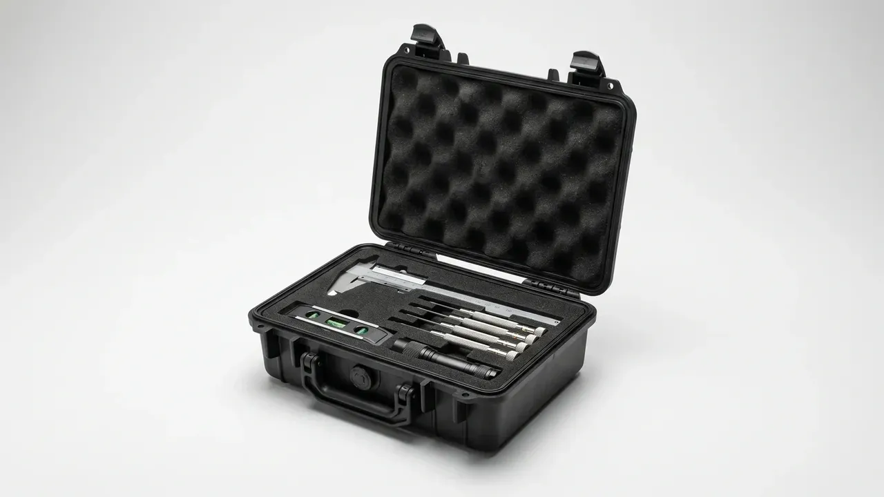
Quick answer: A Custom Case with Foam Insert is specified backwards: lock the smallest clear cavity dimension, split the foam into three layers by part height, then prove the layout on a 1:1 die drawing over two trial fits.
Table of contents
- A Custom Case with Foam Insert Starts at the Cavity
- Fit Clearance Between Insert and Cavity
- Splitting the Foam into Three Layers
- Die Drawings and Trial Fits
- The Drawing Pack You Should Receive
- FAQ
1. A Custom Case with Foam Insert Starts at the Cavity
Datasheets for a Custom Case with Foam Insert usually open with outer dimensions, the easiest order to write and the easiest to get wrong. The shell follows the mould; the cavity holds the equipment, and only once it is fixed can foam thickness be calculated.
Three figures belong there: mouth clearance, floor clearance and smallest clear dimension. Draft pulls three to four millimetres per side between mouth and floor on a 520 by 380 by 190 mm cavity, so long items jam halfway down. The lid recess needs its own figure, or the lid liner eats twenty-odd millimetres.
| Cavity item | What to write | Why it matters |
|---|---|---|
| Clear size | L, W, D plus smallest clear dimension | Draft narrows the floor |
| Lid recess | Say if counted in total depth | Sets usable lid foam |
| Corner radius | Give the R value | Foam corners follow it |
2. Fit Clearance Between Insert and Cavity
The gap between insert and cavity is often written as matched to cavity, which says nothing. It absorbs moulding and cutting tolerance, which stack to plus or minus 1.5 mm, so 2 mm per side is the safe band.
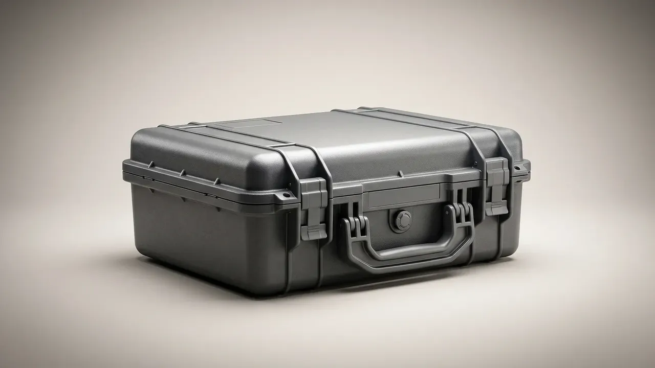
Foam compression is a separate sum. A Custom Case with Foam Insert holds parts at 15 to 25 percent compression; under 15 they rattle, over 25 the slot mouth collapses after repeated use. Past 40 percent of pad thickness the foam densifies and shock passes straight to the shell.
3. Splitting the Foam into Three Layers
Three layers is the common build: base for load, middle for location, lid for hold-down. Base is PE at 45 kg/m³ and 30 mm; middle is EVA at 30 kg/m³ and 20 mm, slotted 3 mm shallower than the part; lid is 25 mm convoluted PU. That totals 75 mm, leaving 115 mm of a 190 mm cavity.
Make the middle a removable block and a Custom Case with Foam Insert takes a second product while base and lid stay. Leave 1 mm of pull clearance plus a half-round notch for fingers, and never glue the layers solid.
4. Die Drawings and Trial Fits
The die drawing must be 1:1 and show outline, slot depth and kerf. Kerf runs 1.5 mm with R3 corners, or the slot cuts burred. Knobs and ports need relief cuts 2 mm larger, or the part bottoms out while the depth looks generous on paper.
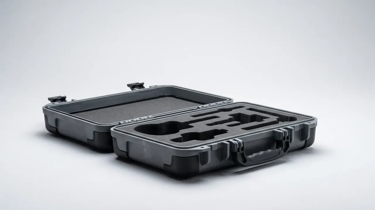
Two trial rounds follow: EVA first, then production foam, five units each, rehearsing load, open, invert and reload. First-article approval then takes 48 hours and files the measurements later batches are judged against.
| Trial round | Material | Units | What it proves |
|---|---|---|---|
| First | EVA trial cut | 5 | Outline and handling feel |
| Second | Production foam | 5 | Compression and lid force |
5. The Drawing Pack You Should Receive
A case often ships with one insert outline, and by the second order nobody knows the slot depth. Six documents prevent that.
| Document | Content | Used for |
|---|---|---|
| Cavity drawing | Clear size, radii, bosses | Tooling and inspection |
| Layer drawing | Three thicknesses, densities | Material planning |
| Die drawing | 1:1 outline and kerf | Cutting and rework |
| Assembly drawing | Layer order, location | Line assembly |
| First-article report | Measured sizes, photos | Batch comparison |
| Material certificate | Density, flame rating | Audit and export |
Version control belongs in the same pack: change the insert drawing and the die, assembly and first-article documents of a Custom Case with Foam Insert step up together, with drawing number and revision marked on every carton.
Conclusion
The order is cavity, clearance, layers, die, documents: the first two decide whether the part fits, the last three whether the build repeats. Put all five on paper with a revision trail, and a Custom Case with Foam Insert can be reordered without starting over.
This article discusses only the container (case body) side of specifications and design intent, and does not cover any handling, loading or use of the contents.
Related Reading
- How a foam insert goes from drawing to finished part
- Cutting methods and kerf accuracy compared
- Which drawings to collect when a custom case ships
- Locating and fixing an insert inside the case body
Related Products
- 8 Series — Gun Cases; Military Equipment Cases; Camera Equipment Cases; Drone Cases; Watch Cases; Knife Cases; First Aid Cases; Electronics Equipment Cases
- WL8-2812 PP Gun Case — model WL8-2812
- All protective cases and toolboxes: 7 series, 158 models