

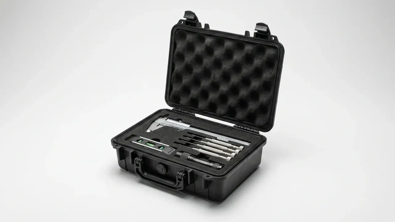
Quick answer: A custom foam instrument case is fixed by four things first: three internal dimensions with tolerances, die spacing, draft angle and drawing checks. Wall thickness and load follow from those.
Table of contents
- The Specification Sheet for a Custom Foam Instrument Case Has Five Parts
- Internal Size and Tolerance: Three Dimensions, No Shortcuts
- Die Spacing and Wall Thickness
- Draft Angle and Cavity Depth
- Drawing Checks and Acceptance
- FAQ
1. The Specification Sheet for a Custom Foam Instrument Case Has Five Parts
Drawings for a custom foam instrument case split into five parts: space, shell, foam, hardware, marking. The first two decide whether the instrument fits.
Each part is written differently: space and shell carry tolerances, foam carries spacing and layers, hardware carries loads, marking only position and colour. Tolerances are the step most often skipped.
| Part | Must state | If left out |
|---|---|---|
| Space | Mouth, base, clear height, tolerance | Will not fit, or rattles |
| Shell | Wall, parting line, ribs | Sags under stacking |
| Foam | Material, density, layers, spacing | Thin walls crack |
| Hardware | Latches, handle rating, hinge | Seats split in transit |
2. Internal Size and Tolerance: Three Dimensions, No Shortcuts
One length by width by depth is not enough. The mouth decides entry, the base how much slack remains, clear height how much room the foam leaves.
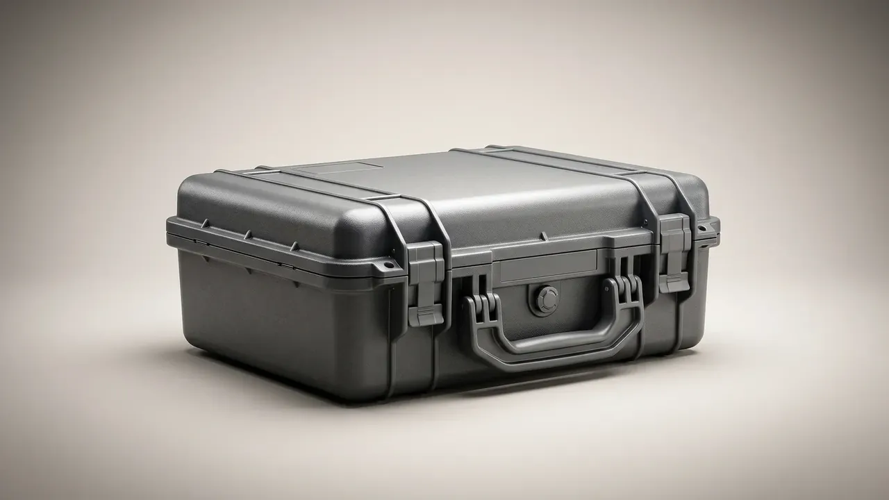
Injection shells take plus or minus 1.0 mm, rotomoulded 2.0 mm. Injection walls are uniform; rotomoulded walls vary with powder dwell time, up to 0.6 mm around one mould.
Draft eats height: at 1.5 percent over 400 mm, the base is 3 mm narrower per side and 6 mm shorter. A custom foam instrument case drawing names both mouth and base sizes, or the draft and its datum.
Foam takes more. With 25 mm in the base, 15 mm in the lid and 3 mm of compression, a 120 mm deep case leaves 77 mm of clear height.
3. Die Spacing and Wall Thickness
Spacing is the solid foam between cavities, or cavity and wall. Die-cut cavities sit at least 6 mm apart and 12 mm from the wall; narrower and the wall shears. A bridge under 5 mm collapses, while 6 to 8 mm holds.
Depth changes the figure: beyond 60 mm of cavity depth, walls go to 8 mm, or the foam lifts with the instrument.
| Location | Minimum spacing | Why |
|---|---|---|
| Between cavities | 6 mm | Die bridge width |
| Cavity to shell wall | 12 mm | Corner squeeze |
| Floor to case floor | 12 mm | Impact on landing |
4. Draft Angle and Cavity Depth
Foam draft is not mould draft; it is the sidewall angle left by the die or router. A custom foam instrument case runs 1.5 to 3 degrees, and a straight wall will not pull past 40 mm.
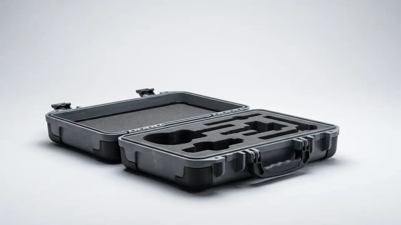
Shell draft counts separately: 1 to 2 degrees per side for injection, 2 to 3 for rotomoulding. Foam following the shell sits better, but deep cavities need another 0.5 degree.
Draft changes capacity. A cavity 100 mm square and 80 mm deep at 2 degrees measures about 94 mm at the floor; drawn at the mouth, the base is 6 mm tight. Floor margin: 12 mm to one kilogram, 20 mm above five.
5. Drawing Checks and Acceptance
Six checks run before a drawing leaves the office; most rework starts here, and one wrong cavity scraps the die.
| Check | On the drawing | How to verify |
|---|---|---|
| Three internal sizes | Mouth, base, clear height, tolerance | Caliper each, take smallest |
| Wall thickness | Nominal plus allowed thinning | Three points per face |
| Foam density | kg per cubic metre, plus or minus 3 | Cut, weigh, convert |
| Cavity spacing | Narrowest solid width | Caliper the narrowest point |
| Load and stacking | 40 kg for 24 hours, three high | Watch for 2 mm of sag |
Acceptance starts at the internal space, then spacing and draft, then latches and handle. Load is tested alone: 40 kg over the lid for 24 hours under 2 mm of sag, stacked three high.
Conclusion
Three groups of numbers define a custom foam instrument case: internal sizes with tolerances, spacing with draft, load with stacking limits. Leave one out and the supplier fills it by habit.
This article discusses only the container (case body) side of specifications and design intent, and does not cover any handling, loading or use of the contents.
Related Reading
- How to write a custom foam insert specification
- Reading an instrument case specification sheet
- Documents needed for a custom protective case
- Foam cutting process and accuracy
Related Products
- 8 Series — Gun Cases; Military Equipment Cases; Camera Equipment Cases; Drone Cases; Watch Cases; Knife Cases; First Aid Cases; Electronics Equipment Cases
- WL8-2812 PP Gun Case — model WL8-2812
- All protective cases and toolboxes: 7 series, 158 models