

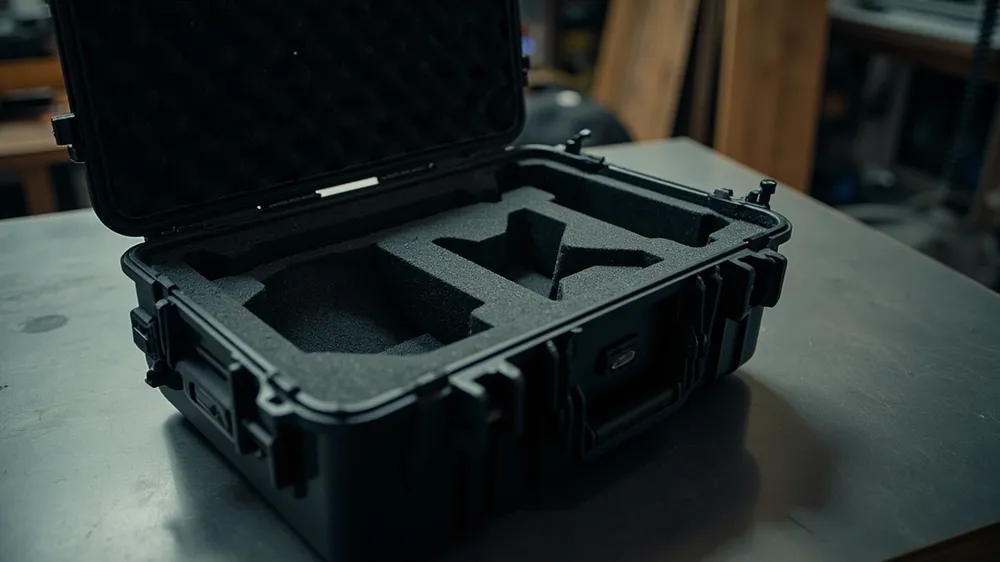
Producing a drone case is far more involved than moulding a shell and cutting a few cavities. From first enquiry to packed shipment it passes through roughly a dozen stages, each with its own technical points and typical defects. Many sourcing disputes happen because the buyer does not know the process and therefore does not know when to ask what — problems only surface once production is already running. This article walks through the real production sequence and sets out what to watch at each stage.
Process Overview
The standard sequence has twelve main stages across four phases: preparation (requirements, design, tooling), forming (material, moulding, interior), assembly (hardware, printing) and verification (inspection, packing). The first three phases set the performance ceiling; the last determines whether delivered quality is stable.
| Phase | Stage | Output |
|---|---|---|
| Preparation | Payload scanning and analysis | Payload list, dimensions, fragile-point map |
| Design and review | 3D model, interior layout, BOM | |
| Tooling and trials | Production tool, trial report, sealed sample | |
| Forming | Material preparation and drying | Resin at acceptable moisture level |
| Shell moulding | Lid, base, internal fittings | |
| Interior fabrication | Formed or cut liner | |
| Assembly | Hardware fitting | Latches, hinges, handles, gasket |
| Printing and marking | Logo, labels, warnings | |
| Verification | Functional inspection | Closure, sealing, load records |
| Visual inspection | Appearance verdict | |
| Performance sampling | Drop, vibration, ingress testing | |
| Packing and storage | Packed goods, storage records |
Stage 1: Payload Scanning and Analysis
This is where the process starts and where hidden problems are most often planted. A responsible factory asks for the actual aircraft or a high-accuracy model rather than working from outline dimensions.
Cavity design needs far more than three dimensions: the spherical gimbal position, the folded propeller profile, the battery bay orientation, antenna locations on the controller, and the shape of each accessory. Boxes built from dimensions alone look fine on paper and fail in the hand.
Three-dimensional scanning to a point cloud, then modelling from it, is the more advanced approach and suits complex aircraft well. Where scanning is unavailable, multi-angle photographs combined with careful manual measurement are the minimum.
The output should be a payload list: name, dimensions, weight and clearly marked fragile areas for every item. That list becomes the baseline for all later design and acceptance work.
Stage 2: Design and Review
With payload data in hand, design settles four things.
Shell specification: internal clearance, maximum external size, wall thickness and material. Internal clearance must hold everything plus cushioning margin; external size must satisfy transport constraints.
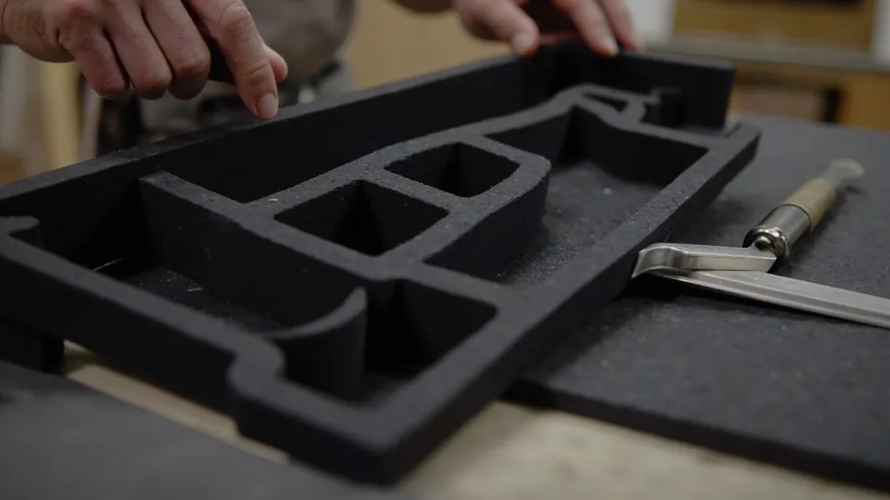
Interior layout: cavity position, depth, spacing and layering. Group by frequency of use, keep heavy items near the handle for balance, and isolate fragile parts.
Hardware: latch count and placement, hinge type, handle style, and whether wheels or a pressure valve are needed. Latch count directly affects how evenly a long lid seals.
Material and process: resin grade, liner material and density, surface finish and print method.
Design should end in a review where the buyer confirms that the layout matches how they actually work, that external dimensions fit their transport, and that materials suit the environment. Changes cost almost nothing at this point.
Stage 3: Tooling and Trials
The tool underpins consistency across the whole run and is the most time-consuming stage. Tooling covers design, steel procurement, rough machining, finish machining, assembly and trials.
Tool design addresses runner type, gate position and count, cooling layout and ejection. These determine whether fill is even, cooling is balanced and the part resists distortion.
Trials validate the tool. First shots usually reveal sink marks, flash, short shots, warp or ejection marks, and two to three rounds of correction are normal before production. Buyers should request trial parts and test them with the real payload.
Note that tooling is usually priced separately and ownership must be settled in the contract. If the supplier owns the tool, switching later is difficult; if you own it, storage and maintenance become yours to arrange.
Stage 4: Material Preparation and Drying
Simple as it looks, this stage causes a surprising share of quality problems. Resins absorb moisture in storage, and they differ greatly in how readily.
PC is notably hygroscopic: moulded without proper drying, vaporised moisture causes bubbles and splay and degrades the polymer, reducing mechanical strength. Such defects often only appear during drop testing, but the root cause sits here.
A capable factory runs drying equipment, sets temperature and time to the material's requirement, and can measure moisture rather than guessing. Whether dryers exist and are actually used tells you a lot about process discipline during an audit.
Grade, batch and colour should all be traceable. Where recycled content is involved, the proportion and its quality controls need stating explicitly.
Stage 5: Shell Moulding
Injection moulding fills the cavity with molten polymer, then cools and ejects the part. One cycle covers clamping, injection, holding, cooling, opening and ejection.
Key parameters — melt temperature, mould temperature, injection speed, injection pressure, hold pressure and time, cooling time — should be recorded rather than left to operator judgement. Records are what make a problem traceable to its cause.
Typical defects: sink marks from uneven wall or insufficient hold; flash from low clamp force or tool wear; warp from uneven cooling or poor ejection; short shots from low melt temperature, slow injection or trapped air.
Parts must cool and stabilise before further processing, or internal stress will release as distortion.
Stage 6: Interior Fabrication
The interior does the protecting, so its quality sets the protection level. Three processes dominate.
| Process | Principle | Accuracy and durability | Best for |
|---|---|---|---|
| Thermoforming | Heated sheet formed over a tool under vacuum | Skinned surface, precise cavities, most durable | Volume production, long service life |
| Die cutting | Shaped blade cuts foam block | Open cells at the cut face, sheds particles | Sampling, small runs, simple shapes |
| CNC routing | Numerically controlled cutter | High accuracy, complex 3D cavities | Tight tolerances, complex geometry |
For drone interiors, thermoforming is usually the volume choice because cavity consistency is best and the skin resists shedding. Suspended gimbal cavities and slender propeller slots both need that accuracy to work.
The governing parameters are density and hardness. Density sets how much energy the foam absorbs; hardness sets how it deforms under load. Both must match payload weight and drop height — too soft bottoms out, too firm transmits shock. Ask the factory to justify the selection rather than accepting a default.
Stage 7: Hardware Assembly
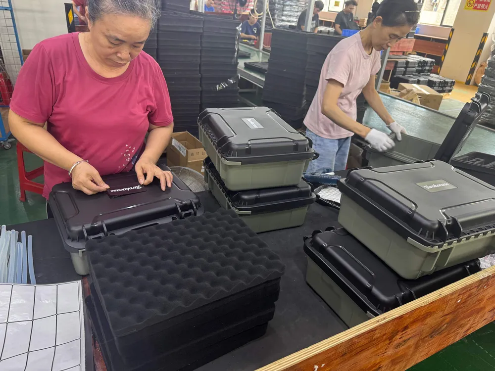
Fitting latches, hinges, handles, gaskets, wheels and valves looks like simple assembly but directly governs sealing and service life.
Gasket fitting is the critical detail. The seal must seat continuously in its groove without twisting or stretching, especially at corners. A gasket that is fitted badly is worse than none, because it creates the impression of sealing. Closing the lid on a strip of paper at several points and comparing resistance around the perimeter is a quick check — see our article on gasket ageing and replacement.
Latch fitting needs consistent torque so the lid and seal are loaded evenly across all points. A torque tool with a set value is the basic control.
Hinge assembly must align the rotation axis of lid and base. Misalignment makes the hinge fight itself on every opening, causing premature wear or cracking. Open and close repeatedly after assembly to confirm smooth action.
Stage 8: Printing and Marking
Logos, text and warnings are applied by printing or labelling. Screen printing, heat transfer, laser marking and in-mould labelling each suit different needs.
Screen printing suits simple artwork and single colours at low cost, with moderate abrasion resistance. Heat transfer handles complex artwork and gradients but needs a flat surface. Laser marking cuts into the shell and never wears off, suiting permanent identification. In-mould labelling fuses the label into the part during moulding — the most durable, but it raises tooling cost.
Choose against the service environment: abrasion-resistant processes for high-contact areas, UV-stable marking for outdoor life, and colour fidelity plus adhesion testing where brand presentation matters.
Stage 9: Functional and Visual Inspection
After assembly, inspection covers function and appearance.
Functional: smoothness of opening over repeated cycles, latch reliability, seal uniformity around the closed gap, handle strength under full load, and operation of wheels, handles and valves.
Visual: sink marks, flash, scratches and colour variation on the shell; print clarity and registration; corrosion, distortion or misalignment of hardware.
Both need written criteria rather than inspector opinion. Production orders should be sampled to an agreed standard, with the sampling rate and acceptance rules settled before ordering.
Stage 10: Performance Sampling
Beyond routine checks, performance sampling verifies that the design target is actually met. For drone cases the key tests are:
- Drop: loaded, at agreed heights and orientations, checking shell, interior and contents. Testing empty tells you very little.
- Sealing: dust and water testing to the claimed ingress rating.
- Vibration: sustained transport vibration to catch loosening hardware and migrating interiors.
- Cycle life: repeated opening to prove latch and hinge fatigue life.
- Stacking: loaded stack testing to check for deformation.
These need not run every batch, but they should run on first production, after any design change and after any material change, with results kept as quality records.
Stage 11: Packing and Storage
The last step shapes what you actually receive. The usual method is a protective bag per case, several cases to a carton, then cartons palletised, which prevents scuffing in transit.
Storage needs stacking limits and moisture control. Sustained stacking causes creep deformation, so observe the stated layer limit; high humidity affects seals and liners. This matches the guidance in our article on warehouse stacking and moisture control.
Stage 12: Typical Defects by Stage
| Defect | Stage | Root cause |
|---|---|---|
| Does not fit / rattles | Payload scanning, interior fabrication | Poor data or insufficient cavity accuracy |
| Sink marks | Moulding | Uneven wall, insufficient hold pressure |
| Flash | Moulding | Low clamp force, tool wear |
| Warp | Moulding | Uneven cooling, poor ejection |
| Bubbles, splay | Drying | Excess moisture |
| Interior shedding | Interior fabrication | Open-cell material or wrong cutting method |
| Water ingress | Hardware assembly | Gasket unseated or uneven latch load |
| Latch loosening | Hardware assembly | Inconsistent torque, no locking provision |
| Print peeling | Printing | Wrong process or no adhesion testing |
| Transit scratches | Packing and storage | No individual protection, poor stacking |
Where the Buyer Should Intervene
Four checkpoints matter most.
Design review: confirm layout, external dimensions and materials. Changes are almost free here, so this is the moment to ask for adjustments.
Trial sample approval: test with the real payload — fit, access, latch action. Do not judge on appearance.
Sealed sample: once satisfied, seal a signed reference and require production to match it in material, structure and finish. This single step prevents most sample-versus-production disputes.
First production acceptance: inspect the first batch against the agreed standard, confirming grade, liner density and hardware model match the sealed sample. Once the first batch is right, later risk drops sharply.
How the Schedule Breaks Down
Roughly: design sign-off about ten per cent, tooling and trials forty to fifty per cent — the longest single block — production about thirty per cent, and inspection and delivery about ten.
Tooling has the most schedule elasticity, driven by complexity and the number of trial rounds. If time is tight, some work can run in parallel, such as preparing materials and packaging while the tool is being cut.
Be aware that compressing the schedule usually means fewer trial rounds or lighter inspection, and both raise production risk. Start earlier rather than cutting necessary stages.
In Summary
A drone case passes through twelve main stages, each with its own technical points and typical defects. Understanding the sequence lets you ask the right question at the right moment and catch problems before production.
Three things are worth remembering: provide the real item or an accurate model rather than dimensions; validate with real payload testing rather than appearance; and seal a sample in the contract so that “acceptable” means the same thing to both sides.
For what a capable factory should look like, see inside a drone case manufacturing factory; for the customisation route itself, see from drawing to approval sample.