

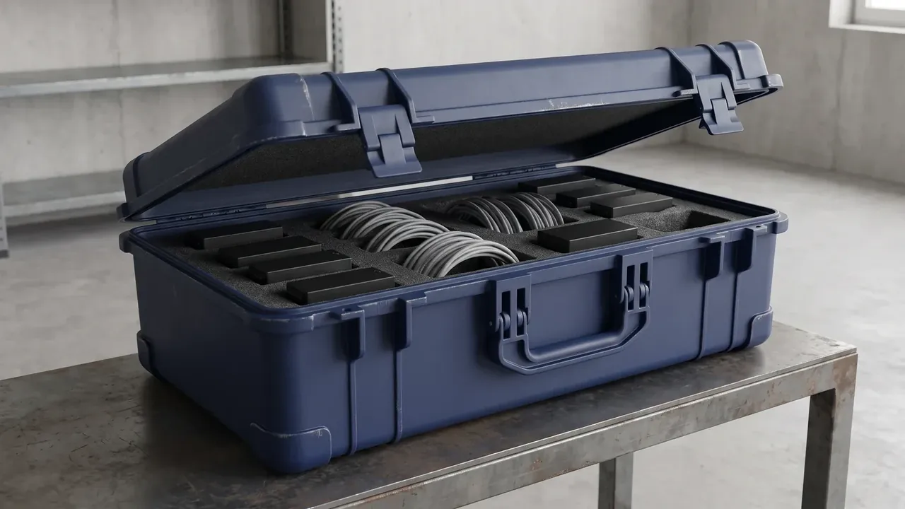
Quick answer: An Electrical Equipment Enclosure serves five situations: outdoor distribution, shop-floor control, temporary power, pump rooms and wellheads, and cabinets bolted to a machine. Most differences come down to ingress protection and heat removal, so fix the IP rating first, the glands second, anti-condensation and earthing last.
Table of contents
- Five Deployment Sites for an Electrical Equipment Enclosure
- Outdoor and Shop Floor: IP Rating and Temperature Rise
- Temporary Power and Pump Rooms: Cabling and Glands
- Skid-Mounted Cabinets: Anti-Condensation and Mounting
- Earthing, Interlocks and the Handover Checklist
- FAQ
1. Five Deployment Sites for an Electrical Equipment Enclosure
Every site asks the same four things: keep water out, keep dust out, keep hands off live parts, and let heat escape. What changes is which of the four binds first.
| Site | Conditions | Design focus |
|---|---|---|
| Outdoor distribution | Sun, rain, day-night swing | IP65 or better, UV-stable shell |
| Shop-floor control | Oil mist, dust, vibration | IP54, sheet thickness, rubber feet |
| Temporary power | Repeated handling and plugging | Industrial sockets, interlock, handles |
| Pump room and wellhead | High humidity, standing water | Anti-condensation, IP66 to IP68 |
| Machine-mounted | Ships with the host unit | Compact outline, document pocket |
The order matters. Ingress protection sets the door gap, gasket and cut-out style; heat removal follows, because cooling hardware eats internal volume; cabling comes last, since once the gland holes are punched an Electrical Equipment Enclosure is frozen.
2. Outdoor and Shop Floor: IP Rating and Temperature Rise
For an Electrical Equipment Enclosure the first IP digit covers solids, the second water. A point under a canopy is fine at IP54; a corner that gets hosed down needs IP65 or IP66. IP66 stops a jet, not standing water.
Rise is the number most often skipped: internal air minus ambient, read after two hours at steady load. Derating curves sit at 40 °C or 55 °C, so holding 15 K keeps the margin.
Natural convection follows surface area and free vent area. Airflow is roughly 3.1 times internal loss divided by permitted rise. A 200 W loss at 15 K needs about 41 m3/h, and a dusty filter cuts that to seventy percent, so specify 60 m3/h.
| Cooling method | Loss range | What controls the rise |
|---|---|---|
| Natural convection | Below 100 W | Offset louvres, larger top surface |
| Fan with filter | 100 to 500 W | 20-mesh media, quarterly cleaning |
| Air conditioner | Above 500 W | Thirty percent capacity margin |
| Heat exchanger | Dust or oil mist | Separate internal and external air paths |
3. Temporary Power and Pump Rooms: Cabling and Glands
Cables leave through the bottom and form a drip loop, so water runs off the sheath. Glands follow cable diameter: M20 for 6 to 12 mm, M25 for 11 to 17 mm, on 22.5 mm and 28 mm holes, kept 20 mm clear of the wall edge.
A temporary-power unit is carried around, so insertion force lands on the socket base; bolt sockets to a reinforcing plate. A pump-room Electrical Equipment Enclosure never moves but lives above ninety percent humidity, so the bottom entry gets two seals, one for water and one for vapour. Where a wellhead can flood, fit IP68 connectors.
4. Skid-Mounted Cabinets: Anti-Condensation and Mounting
Condensation forms when the wall drops below dew point, which is not leakage. An Electrical Equipment Enclosure that loses power overnight cools below its internal air, moisture beads inside, and morning energisation is when faults show. A 50 W heater switching at 5 °C and 15 °C keeps the wall warmer.
The companion part is a breathable vent: pressure swings in transit flatten the gasket for good. Wall units need 100 mm off the wall and 600 mm in front, floor units sit on a 100 mm plinth, pole units use a 76 mm clamp.
5. Earthing, Interlocks and the Handover Checklist
Earthing of an Electrical Equipment Enclosure depends on the system: a separate earth is held to 4 ohms, bonding under 0.1 ohm between door and body. Use 6 mm2 green-yellow conductor with slack at the hinge.
Interlocking is the floor for live work: the door cannot open with the switch closed, and the switch cannot close with the door open. Size the window for gloves, 3500 mm2 or more, so breaker position stays readable.
Handover runs in three passes: spray the gap for five minutes with paper inside, check for any through gap above 0.3 mm, then log the rise during a two-hour run.
Conclusion
The five sites differ in how environment, losses and cable entries pull the specification apart. Fix the IP rating, rise margin and hole pattern in that order, add bonding, and one Electrical Equipment Enclosure covers most jobs from a shop-floor corner to a wellhead.
This article discusses only the container (case body) side of specifications and design intent, and does not cover any handling, loading or use of the contents.
Related Reading
- Explosion-proof cavity design
- Cooling methods for vehicle and rack cases
- Sealing layers of equipment protection cases
- Ingress ratings for waterproof hard cases
Related Products
- 8 Series — Gun Cases; Military Equipment Cases; Camera Equipment Cases; Drone Cases; Watch Cases; Knife Cases; First Aid Cases; Electronics Equipment Cases
- WL8-2812 PP Gun Case — model WL8-2812
- All protective cases and toolboxes: 7 series, 158 models