

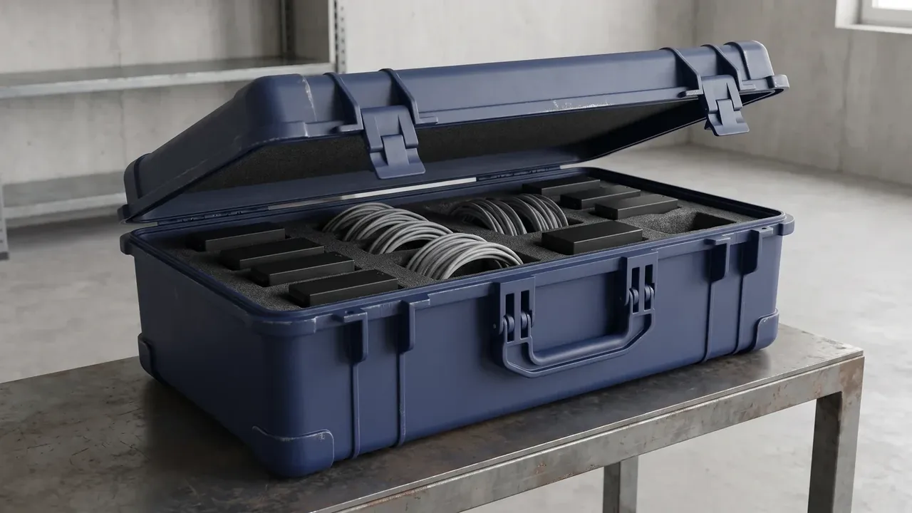
Quick answer: An electronic equipment protective case covers field testing, base station spares, radar and antenna unit transfer, and bench moves between laboratories. The differences sit in ESD protection and grounding, shielding and wall penetrations, cushioning and fixing, and power and cable management.
Table of contents
- Where an Electronic Equipment Protective Case Is Used
- ESD Protection and Grounding Start With Surface Resistance
- Shielding and Wall Penetrations: Seams and Holes
- Cushioning and Fixing: Modules and Harnesses
- Power Feed and Cable Management
- FAQ
1. Where an Electronic Equipment Protective Case Is Used
Field testing is the noisiest duty: the case is loaded and unloaded two or three times a day, set on grass or gravel, opened while power and signal lines stay connected. What gets tested is the penetration seal and the cable anchoring.
Base station spares sit still: an electronic equipment protective case may hold parts for three to six months at minus twenty to fifty-five degrees Celsius and high humidity, and three-high stacking puts close to eighty kilograms on the bottom case.
Radar and antenna units travel short distances with the risk in static and impact: a metal housing rubbing an insulating insert builds charge that lands on a waveguide or coaxial pin.
| Scenario | Dwell time | Priority | Typical failure |
|---|---|---|---|
| Field testing | One to three days | Penetration seals | Water at ports |
| Base spares | Three to six months | Stacking and dryness | Compressed foam |
| Radar units | Hours | Liner and port caps | Static damage |
| Bench moves | Half a day | Grounding | Poor ground |
2. ESD Protection and Grounding Start With Surface Resistance
Surface resistance on an electronic equipment protective case is the first number, measured at one hundred volts. Conductive material sits between ten to the fourth and ten to the sixth ohm and drains charge almost instantly; dissipative material sits two to three decades higher, draining slowly enough to spare devices a violent discharge.
Grounding completes the path: M6 studs at four newton metres, case-to-earth under one ohm, a conductor of at least six square millimetres. A stud that bites only into coating looks grounded and measures tens of ohms.
| Material | Surface resistance (Ω) | Drain path | Use |
|---|---|---|---|
| Conductive | 10^4 to 10^6 | Direct to earth | Modules, bare boards |
| Dissipative | 10^6 to 10^9 | Via one megohm | Units, harnesses |
| Insulating | Above 10^12 | None | Outer structure |
The usual gap sits between liner and operator: a wrist strap and a separately grounded case share no common point, so both belong on one bus bar.
3. Shielding and Wall Penetrations: Seams and Holes
Shielding effectiveness is quoted in decibels. At one gigahertz an electronic equipment protective case with coating and gasket reaches forty to sixty decibels, and beyond that the limit is seams and holes.
The lid edge is the longest seam. Screw spacing over fifty millimetres turns it into an antenna, and gasket compression belongs near thirty per cent, since tighter takes a permanent set and looser leaves contact resistance high.
Vent arrays under three millimetres per hole give about fifty-two decibels; a thirty-two millimetre cable flange drops to thirty-eight and needs an O-ring to recover the gap.
4. Cushioning and Fixing: Modules and Harnesses
Cushioning follows unit mass. Twenty-five millimetres of polyethylene foam under a four-point plate absorbs a thirty g, eleven millisecond half-sine shock, and four M4 screws with lock washers hold better than foam alone.
A bend radius under six times the cable diameter fatigues copper, and tie spacing beyond three hundred millimetres lets bundles swing into the pocket wall. An electronic equipment protective case wants separate channels tied to ribs rather than to foam.
5. Power Feed and Cable Management
Powered tests need one protected feed on the case: a 220 volt input through a thirty milliamp residual current device and a 65 watt DC module, with the device in an outside bay and never in a signal channel.
| Penetration | Opening (mm) | Shielding (dB) | Ingress |
|---|---|---|---|
| Vent array | 3 | 52 | IP54 |
| Circular flange | 32 | 38 | IP67 |
| Interface plate | 80 × 40 | 45 | IP66 |
Cables on an electronic equipment protective case need strain relief. Loaded directly at the opening, the jacket is cut by the edge and the copper fails later; a clamp moves the load into the case body.
Conclusion
The four scenarios weight the requirements differently: sealing for field work, stacking for spares, static for transfer, grounding for bench moves. Writing those four as measurable numbers is what makes an electronic equipment protective case fit powered equipment.
This article discusses only the container (case body) side of specifications and design intent, and does not cover any handling, loading or use of the contents.
Related Reading
- Four scenarios for electronic equipment cases
- How electronic equipment cases are built
- EMI shielding case design points
- Communication equipment case problems
Related Products
- 8 Series — Gun Cases; Military Equipment Cases; Camera Equipment Cases; Drone Cases; Watch Cases; Knife Cases; First Aid Cases; Electronics Equipment Cases
- WL8-2812 PP Gun Case — model WL8-2812
- All protective cases and toolboxes: 7 series, 158 models