

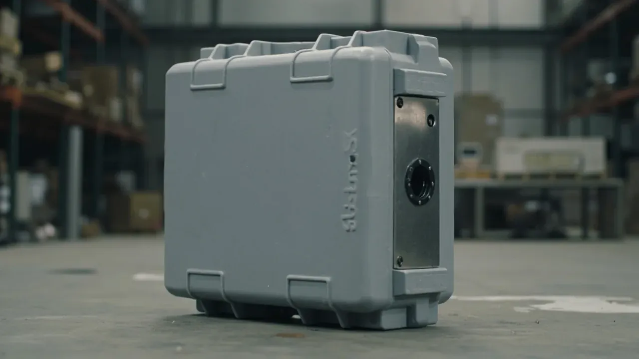
Quick answer: Write an EMI shielding case specification in three groups: attenuation as band plus decibels, gasket compression plus contact resistance, and interface loss plus mounting. A single figure such as 60 dB says little, because low-frequency magnetic fields and high-frequency plane waves differ by an order of magnitude, and a bare shell can beat a finished case by 20 dB. Compression runs 25 to 40 percent, contact resistance stays under 10 milliohms per point, and drilling comes before coating.
Table of contents
- Attenuation: band and decibels together
- Gaskets: compression paired with contact resistance
- Interfaces: filters versus waveguides
- Process order: drill first, coat second
- Five rows into the purchase clause
- FAQ
1. Attenuation: band and decibels together
Shielding difficulty in an EMI shielding case changes with frequency. A low-frequency magnetic field needs a permeable path to divert flux, and a thin coating does nothing for it; plane waves reflect from a conductor. A bare 60 dB figure says nothing about either end.

Separate the bare shell from the finished case. A shell alone reaches 80 dB, yet unfiltered connectors and one under-clamped seam drop the unit to 30 dB. Buy the complete EMI shielding case, measured as clamped, with margin for poor repeatability.
2. Gaskets: compression paired with contact resistance
In an EMI shielding case the gasket is the only conductive path between lid and body. Filled silicone is stable between 25 and 40 percent compression; below 20 percent a rough moulded surface makes contact intermittent, and above 50 percent the gasket takes a set.
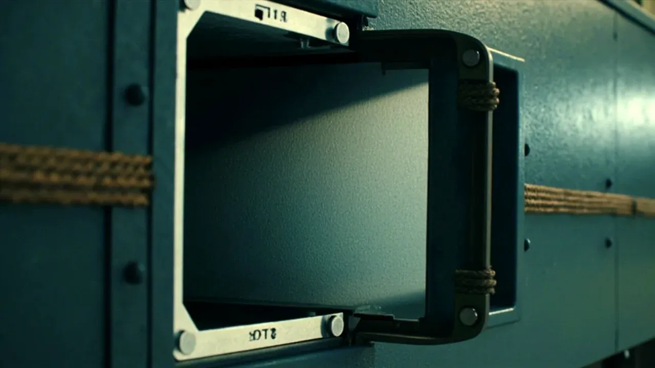
Hold contact resistance under 10 milliohms per point, continuous around the perimeter. The groove floor must conduct, since a gasket pressed onto release agent sits on plastic. Silver filler corrodes against aluminium, so wet service takes nickel-graphite.
3. Interfaces: filters versus waveguides
Every conductor crossing the shell of an EMI shielding case needs treatment. A filtered connector returns 40 to 60 dB above 100 MHz, with high density and simple mounting, but fixed capacitance and a high unit price. A waveguide tube works only below cutoff.
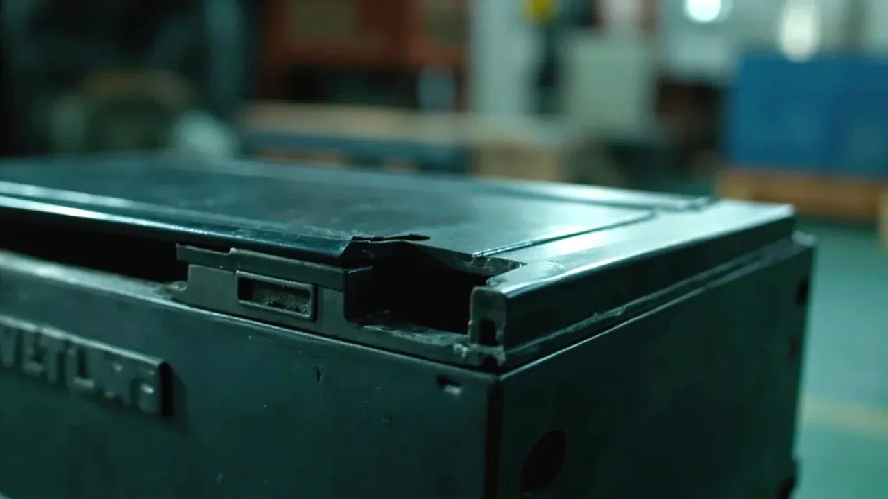
Power takes filtered connectors, ventilation honeycomb, fibre a metallised sleeve. On an EMI shielding case large holes weaken the wall, so group connectors on a bolted plate, gasket it all round and let it reinforce.
4. Process order: drill first, coat second
Get the order wrong on an EMI shielding case and nothing downstream recovers. Drill, prepare, mask, prime, topcoat, cure, then fit gasket, plate and terminal. Coat before drilling and every hole edge shows bare polyethylene, so nothing conducts.
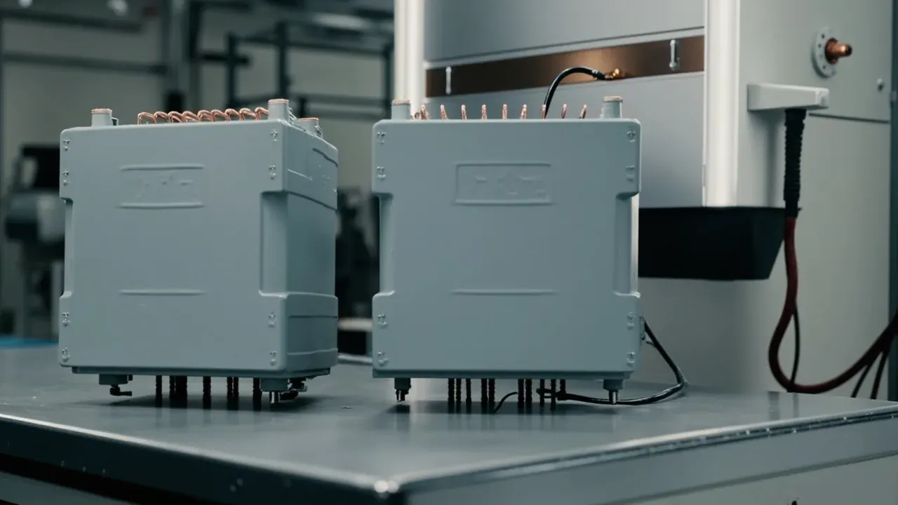
The polyethylene of an EMI shielding case has a surface energy near 31 millinewtons per metre, too low for paint, so flame or plasma treat it to 38. Decorative paint insulates, so a sprayed terminal is a disconnected terminal.
5. Five rows into the purchase clause
Collected into one table for an EMI shielding case, the specification becomes a purchase clause. Every row needs an acceptance method, or the number is an adjective: a chamber for shielding, probes for resistance, a cut section for compression.
Wall thickness is deliberately absent from an EMI shielding case sheet. It governs drop and stacking, not shielding. What deserves its own list is the interface schedule: how many holes, of what type, filtered or not, at what loss.
| Parameter | Typical value | What it governs | How to check |
|---|---|---|---|
| Case shielding | 30 MHz to 1 GHz, 40 dB or more | the final result | chamber, as clamped |
| Surface resistance | 0.1 ohm per square or less | current spreading | four-point probe, five readings |
| Bond resistance | 10 milliohms or less | ground return quality | micro-ohmmeter, terminal to shell |
| Gasket compression | 25 to 40 percent | contact against rebound | cut section under a projector |
| Interface loss | 40 dB or more above 100 MHz | the cable-entry leak | network analyser, port by port |
Conclusion
Specify an EMI shielding case in order: band and case-level figure first, gasket and interface detail second, process sequence last in the work instruction. The band picks the material route, the gasket closes the longest seam, the interface covers the path everyone forgets, and the order decides whether the first three survive the shop floor. Only that last item can be checked piece by piece at the bench, and it is the one most often left out of the annex.
This article covers container-side specifications and design implications only, not the handling, loading or use of the contents.
Related Reading
- Shielding, grounding and sealing in a shielding case
- Electronic Equipment Case: Vibration and ESD Protection
- Lid latches and sealing design
- Transit Cases: Reusable Equipment & Instrument Protection
Related Products
- 8 Series — Gun Cases; Military Equipment Cases; Camera Equipment Cases; Drone Cases; Watch Cases; Knife Cases; First Aid Cases; Electronics Equipment Cases
- WL8-2812 PP Gun Case — model WL8-2812
- All protective cases and toolboxes: 7 series, 158 models