

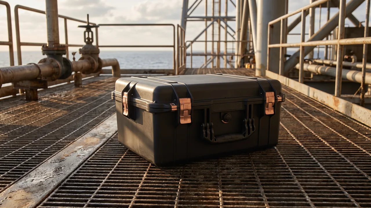
In calibration laboratories, semiconductor maintenance depots, rail inspection units and emergency response teams, instruments travel continuously between the store, the vehicle and the job site. Every handling event is an impact input. Every rainy unloading is an opportunity for moisture ingress. And the equipment inside is frequently worth tens of thousands of dollars, with an appearance grade and a calibration status that must survive the trip unchanged. This is a fundamentally different problem from conventional packaging, where the objective is simply to deliver once and dispose of the crate.
The design principle JUNZHIJIA applies to this class of logistics is straightforward: treat the transit case as a maintainable asset that is inspected and repaired on a schedule, not as a single-use carton with a thicker wall. That principle has concrete consequences: seal gaskets must be replaceable as a line item, latches must be purchasable as spares, foam liners must be re-millable when a new instrument model arrives, and the shell must hold its closed dimensions after several hundred clamping cycles.
Table of Contents
- What Counts as a Transit Case: Definition and Boundaries
- Shell Structure and Load Path: Stacking, Lifting and Fork Handling
- Sealing and Pressure Equalisation: IP65 or IP67?
- Cushion Systems: From Milled Foam Blocks to Segmented Cavities
- Fixturing Instruments: Face Flanges, Dividers and Locating Blocks
- Moisture, Temperature and Corrosion Control
- Latches, Hinges and Tamper-Evident Seals
- Transport Test Verification: ISTA, GB/T 4857 and ASTM D4169
- Service Life, Inspection Intervals and Component Replacement
- Five-Year Cost of Ownership Against Single-Use Packaging
- Customisation, Minimum Order Quantity and Acceptance Criteria
- Industry Applications and a Practical Selection Checklist
- Frequently Asked Questions FAQ
- Conclusion and Related Reading
What Counts as a Transit Case: Definition and Boundaries
The term reusable container covers a wide spectrum. Plastic tote bins, folding sleeve pallets and open crate boxes are all described as reusable, yet their protection goal is limited to keeping goods from spilling in a warehouse. A transit case is held to a much higher standard because it performs three roles simultaneously: shipping package, mobile workstation and field storage cabinet.
Three boundary conditions determine whether a project genuinely needs a transit case rather than a container. The first is trip frequency. If the same equipment travels more than six round trips per year, the consumable and labour cost of single-use packaging quickly exceeds the depreciation of a reusable shell. The second is unit value and calibration status. When an instrument must maintain metrological traceability, or when a cosmetic scratch constitutes a failed acceptance, the package has to provide deterministic restraint rather than approximate padding. The third is environmental exposure. Outdoor work, rain during loading, coastal salt fog and dusty production floors each test a different capability: sealing, corrosion resistance and dust exclusion respectively.
A further distinction matters in practice: one instrument per case, or one complete work unit per case. Instruments, cables, brackets, probes and calibration certificates usually form a single operational kit, and shipping them separately forces re-assembly and re-verification at the site. The internal partitioning of a transit case therefore often determines operating efficiency more than shell strength does. A useful reference on partitioning approaches is available in the comparison of foam types used inside protective cases.
| Usage pattern | Round trips per year | Primary shell requirement | Recommended structure |
|---|---|---|---|
| --- | --- | --- | --- |
| Intra-lab circulation | Over 20 | Light, visible, stackable | Thin-wall rotomoulded shell with EVA dividers |
| Intercity road freight | 8–20 | Vibration and stacking resistance | Ribbed shell with single-block milled liner |
| Long-term field deployment | 3–8 | Corrosion, dust and insect resistance | High-grade seal with desiccant bay |
| Air travel with personnel | 6–15 | Weight sensitive, compliant locks | Aluminium frame or thin composite shell |
Shell Structure and Load Path: Stacking, Lifting and Fork Handling
Structural loads on a transit case fall into four categories. Static stacking occurs in the warehouse and is a long-duration load that tests creep resistance of the walls. Dynamic stacking occurs while the vehicle is moving; the load is pulsating and peaks typically reach 1.6 to 2.0 times the static value. Lifting and fork handling produce severe local stress concentration. Single-point drop tests the corners and the base.
The standard engineering answer is a stiff shell with a compliant core. An integrally moulded outer shell with reinforcing ribs carries bending and torsion, while an independent liner absorbs shock, and the two are connected through locating channels rather than bolts so that an impact cannot tear them apart. The mating faces between base and lid need a locating lip, typically 8 to 12 mm tall. The lip restrains lateral movement during stacking without creating an interference fit that makes opening difficult.
Rated load capacity must separate static stacking load from transport stacking load, and confusing the two is one of the most common selection errors. A practical rule is that the transport stacking height should not exceed 70 percent of the statically tested height, and lateral restraint straps should be used inside the vehicle so that part of the stacking load is converted into strap tension.
| Case size (internal L×W×H, mm) | Empty weight | Static stacking | Transport stacking | Maximum payload |
|---|---|---|---|---|
| --- | --- | --- | --- | --- |
| 450×330×200 | 2.8 kg | 6 high | 4 high | 18 kg |
| 620×470×320 | 6.4 kg | 5 high | 3 high | 40 kg |
| 800×600×450 | 11.5 kg | 4 high | 3 high | 75 kg |
| 1200×800×600 | 24.0 kg | 3 high | 2 high | 150 kg |
These payload figures assume a well-fitted liner. Where a cavity gap of 20 mm or more exists, the contents gain extra travel during a drop, and the practical payload must be reduced by 20 to 30 percent.
Sealing and Pressure Equalisation: IP65 or IP67?
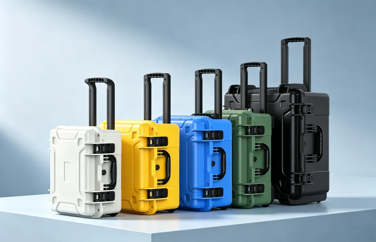
Ingress protection ratings follow IEC 60529 and its national equivalents. The first digit addresses solid particle protection, the second addresses water. In transit applications the recurring argument is whether IP67 is genuinely necessary. IP65 requires protection against water jets; IP67 requires no ingress after 30 minutes immersed at one metre. The structural difference lies not in the gasket material but in the number of sealing interfaces and the uniformity of compression force across them.
An IP65 case typically has a single primary interface between lid and base, usually combined with a drainage lip that carries small accumulations of water away. IP67 requires every possible path to be closed: the primary interface, latch mounting holes, hinge pins, the pressure equalisation valve and any cable entry. Each additional interface is another location where compression must be maintained over years of service, and therefore another potential ageing failure point.
In transit service the more consequential component is often the pressure equalisation valve. Altitude change, temperature change and solar loading create a differential between the inside and outside of the case. For a 60-litre case moved from sea level to a site at 2000 metres, the differential can exceed 20 kPa, equivalent to roughly 1.2 tonnes of force distributed across the lid. On the return trip from a cold store into a hot vehicle the differential reverses. A case without equalisation suffers one of two outcomes: the gasket is crushed into permanent deformation, or opening the case requires excessive force and the lid can spring back dangerously.
The correct solution is a hydrophobic membrane vent that passes gas while blocking liquid and dust. Typical airflow is in the range of 100 to 500 ml per minute, fast enough to equalise pressure but restrained enough that breathing does not carry moisture into the case. For a detailed comparison of valve constructions, see the explanation of how pressure equalisation valves work.
| Protection target | Sealing interfaces | Equalisation valve | Typical application | Common failure mode |
|---|---|---|---|---|
| --- | --- | --- | --- | --- |
| Dust and splash | 1 | Optional | Indoor circulation | Lip contamination prevents closure |
| IP65 water jets | 1–2 | Recommended | Rain loading, short outdoor work | Compression set in the gasket |
| IP67 immersion | 3–5 | Mandatory | Water crossings, vessel decks | Blocked membrane makes opening hard |
| IP67 with corrosion control | 3–5 | Mandatory | Coastal and chemical sites | Galvanic corrosion at hinge pins |
Cushion Systems: From Milled Foam Blocks to Segmented Cavities
The cushion is the most underestimated element of a transit case and the one most likely to determine success or failure. Its task is not to fill empty space but to keep the acceleration transmitted to the equipment surface below the allowable limit for a given drop height and shock pulse. Material differences are substantial, and choosing badly can be worse than having no liner at all.
Expanded polyethylene, commonly known as EPE, sits at 20 to 30 kg/m³. It has good rebound and low cost, suits light and regular shapes, but loses thickness gradually under sustained compression, which makes it a poor choice for a case that will be reused for years. EVA copolymer foam at 60 to 90 kg/m³ exhibits very low compression set and can be milled into complex cavities, making it the mainstream choice for instrument transit cases, with the drawback of higher unit cost and the need for CNC tooling. Cross-linked IXPE has a high closed-cell ratio and very low water absorption, suitable for damp environments, though it is softer and has modest tear resistance. Polyurethane foam offers a wide density range and suits irregular cushioning layers, but it is formulation sensitive and batch consistency must be controlled.
The combination found most often in practice is an EVA primary liner, an IXPE base pad, and EPE fill in non-load-bearing areas. EVA carries and locates the load, IXPE isolates the base against moisture and provides slight compliance, and EPE is used only where no load path exists, avoiding waste of high-density material. A typical thickness split is 6:3:1, with the actual figures back-calculated from drop height and allowable acceleration.
| Material | Density kg/m³ | Compression set | Water absorption | Machinability | Payload band |
|---|---|---|---|---|---|
| --- | --- | --- | --- | --- | --- |
| EPE | 20–30 | High | Low | Fair | Under 8 kg |
| EVA | 60–90 | Very low | Low | Excellent | 5–60 kg |
| IXPE | 30–60 | Low | Very low | Good | Under 15 kg |
| Polyurethane | 40–200 | Medium | Medium | Excellent | Formulation dependent |
Fit tolerance between liner and equipment should be held between 0.5 and 1.5 mm. A loose fit gives the equipment extra travel during a drop, and measured acceleration can rise by more than 30 percent. An excessively tight fit makes loading difficult, and operators will eventually stop using the fixture correctly, which creates a larger risk than the one it was meant to solve.
Fixturing Instruments: Face Flanges, Dividers and Locating Blocks
When a case must carry a complete operational kit, the fixturing method determines how long site restoration takes. Four approaches dominate, each with clear applicability.
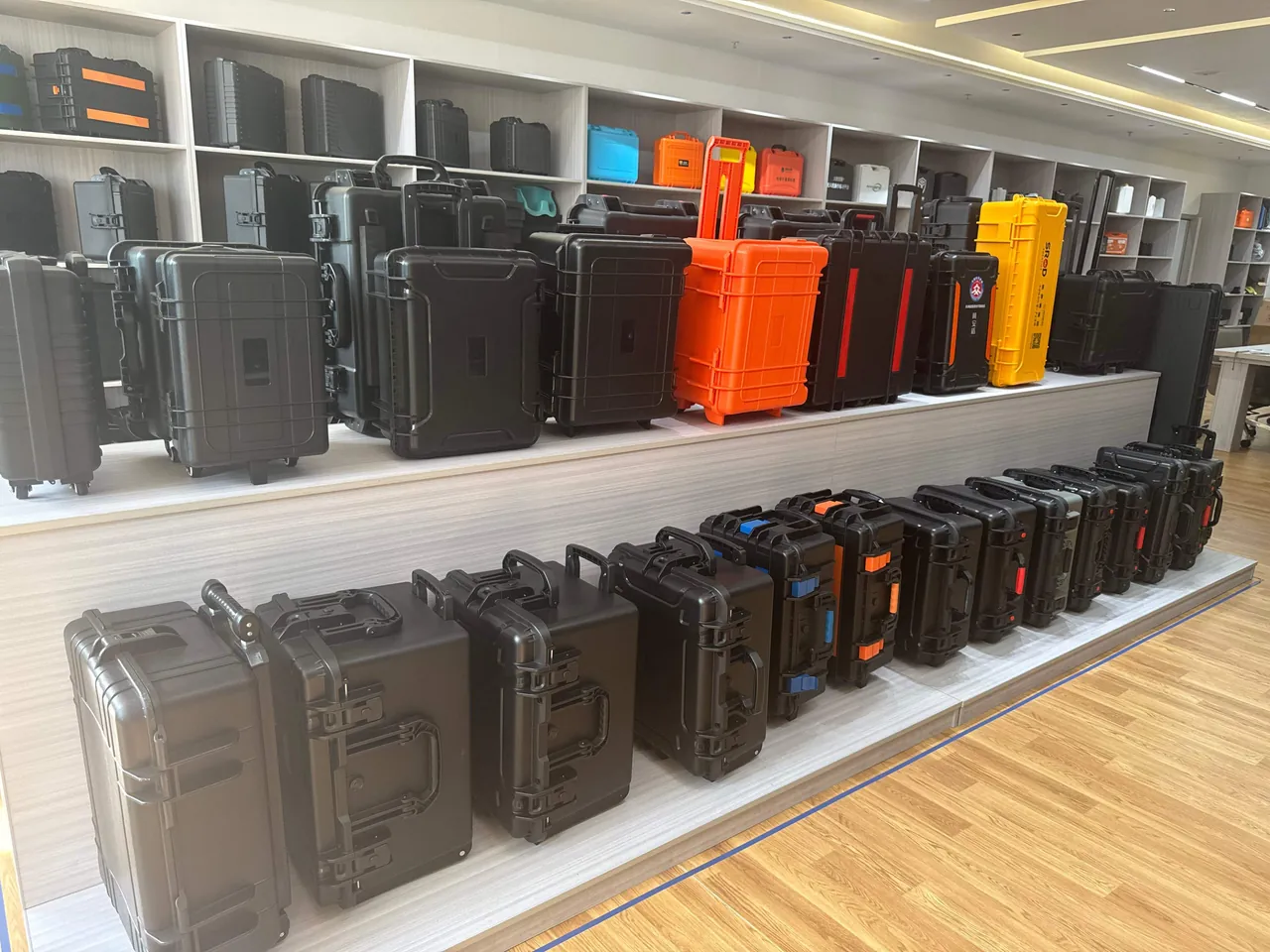
Single-block milled cavities deliver the best fit and the most uniform cushioning, but they suit only one instrument model, and a model change renders the entire liner obsolete. Removable dividers combine rigid boards with soft edge trim to form a reconfigurable grid. They adapt well, but the divider's own stiffness creates a new concentrated load under impact, so at least 5 mm of compliant material must sit beneath the divider. Locating blocks with straps suit irregular shapes: a few blocks define position and webbing straps clamp the load. Loading is fast, but strap tension depends on operator consistency. Face flange clamping uses the instrument's own mounting holes and a clamp plate to lock it to the liner, appropriate for instruments with a rigid base.
The deciding question is whether the site requires rapid retrieval. If an operation involves unpacking, extracting and setting up within three minutes, any liner design requiring screwdrivers will be bypassed. In that case locating blocks with straps should be preferred, and the strap buckles should be operable one-handed.
Moisture, Temperature and Corrosion Control
In hot and humid regions the dominant threat is not external rain but internal condensation driven by the day-night temperature cycle. During the day the shell warms in sunlight, internal air expands and discharges through the vent. At night the shell cools, humid outside air is drawn back in, and water vapour condenses on metal surfaces that cool faster than the surrounding air. The cycle repeats daily, and after a month visible staining and mould can appear.
Three countermeasures matter. First, limit air exchange by selecting a vent with lower airflow, which reduces the net moisture migration caused by breathing. Second, install a desiccant bay with molecular sieve or silica gel to absorb residual vapour. Dosage can be estimated from free volume: starting from 25 degrees Celsius at 60 percent relative humidity, holding below 40 percent for 90 days requires roughly 25 to 40 grams of silica gel per 10 litres of free volume, with a humidity indicator card bonded inside for inspection. Third, ensure the liner itself does not absorb water. High closed-cell IXPE or film-faced EVA prevents foam from becoming a moisture reservoir.
Corrosion resistance of metal parts and platings is evaluated with neutral salt spray testing to GB/T 10125 or ISO 9227. Typical metal components include latches, hinge pins, the vent housing and caster brackets. Galvanic corrosion deserves particular attention: an aluminium case with stainless steel hinge pins used in a coastal environment will often show pitting at the contact face within one or two years. Standard remedies are insulating washers, matching material pairs, or hard anodising on the aluminium parts.
Latches, Hinges and Tamper-Evident Seals
A transit case latch is not a consumable, but its wear parts are the spring and the pin. Evaluation should look at three numbers: the torque required for one-handed opening, the preload in the closed position, and the retention force after 5000 open-close cycles. As a rule, preload between 0.8 and 1.2 mm balances sealing against ease of use. Below 0.5 mm the gasket is under-compressed; above 1.5 mm one-handed opening becomes impractical.
Hinge design must limit the lid opening angle. Without a stop, a lid opened beyond about 100 degrees forms a lever against the rear wall, and a drop can tear the hinge out at the root. Limited hinges typically constrain travel to 95 to 105 degrees and provide a metal stop at the extreme position.
Tamper-evident sealing is an overlooked but valuable element of transit management. A numbered single-use tie or security label applied over the latch achieves three things: it confirms the case was not opened between departure and return, it localises the point of loss when something goes missing, and it creates a usage history when the seal numbers are entered into a register. For instruments requiring metrological traceability, that register becomes the evidence chain during an audit.
Transport Test Verification: ISTA, GB/T 4857 and ASTM D4169
Verification must rest on a defined test sequence rather than an impression of sturdiness. The ISTA series is widely used internationally: ISTA 2A covers packages under 68 kg and combines conditioning, drop, random vibration and compression, while ISTA 3A is a general simulation performance test with a vibration spectrum closer to full vehicle transport. ASTM D4169 offers test sequences configured by distribution cycle, which suits situations where a common acceptance basis must be agreed with a customer. In China, the GB/T 4857 series applies, with GB/T 4857.5 for drop, GB/T 4857.23 for random vibration and GB/T 4857.3 for static load stacking.
| Test | Common standard | Example parameters | Pass criterion |
|---|---|---|---|
| --- | --- | --- | --- |
| Drop | ISTA 2A / GB/T 4857.5 | 10 drops on corners, edges, faces at 600–900 mm | Contents functional, no displacement |
| Random vibration | ASTM D4169 DC13 | 0.5–0.7 g rms for 1–2 hours | No structural cracking, latches intact |
| Static stacking | GB/T 4857.3 | 2× load for 24 hours | Deflection 3 mm or less |
| Water jet | IEC 60529 IPX5 | 12.5 mm nozzle at 6.3 L/min | No visible internal ingress |
| Salt spray | GB/T 10125 | 48 hours neutral salt spray | No red rust, pitting within limits |
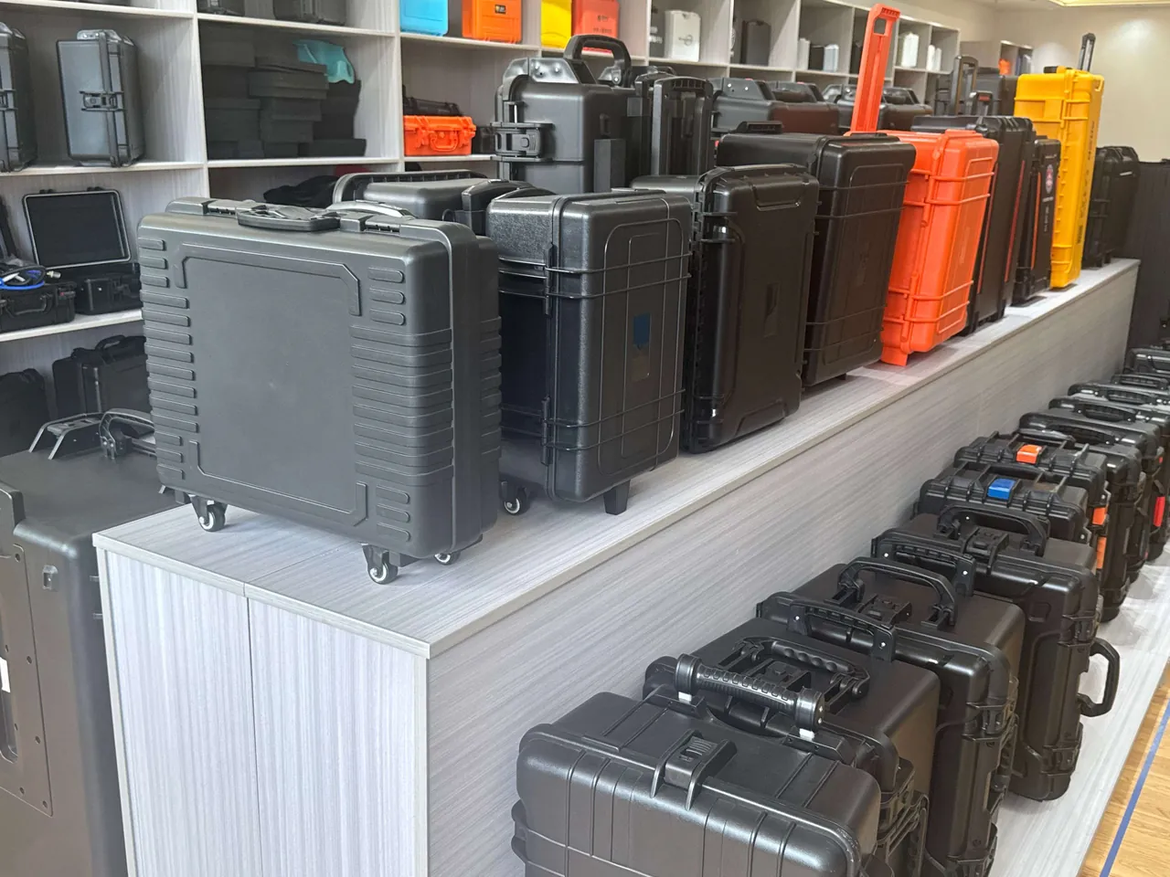
Two recurring mistakes appear in test planning. The first is setting drop height from the nominal handling height at the site, which usually produces an optimistic figure; the correct approach derives height from the 95th percentile of a distribution environment survey. The second is testing a single case in isolation without reproducing a stacked condition, when the greatest real-world risk is often the toppling of a stacked column.
Service Life, Inspection Intervals and Component Replacement
Managing a transit case as an asset requires an inspection regime comparable to that applied to machines. The purpose is not to scrap damaged cases but to replace parts before failure, so that the case does not fail in transit and destroy the equipment it carries.
| Component | Interval | Criterion | Action |
|---|---|---|---|
| --- | --- | --- | --- |
| Main gasket | Every 20 trips or quarterly | No cracking or permanent flattening; rebound to 90 percent of original thickness | Replace the full loop |
| Vent valve | Every 50 trips or half-yearly | Free airflow, membrane free of dust build-up | Clean or replace |
| Latch springs | Every 100 trips | One-hand operation, no lost motion when closed | Replace latch |
| Hinge pins and bushes | Annually | No axial play, no corrosion binding | Re-grease or replace |
| Liner cavities | Quarterly | Fit gap to equipment 2 mm or less | Patch or re-mill |
| Shell surfaces | Half-yearly | No through-cracking, no scratch deeper than 2 mm | Assess and downgrade |
Numbering each case and keeping a register is recommended, recording the production date, cumulative trip count, replacement history and any downgrade. When a case moves from carrying precision instruments to carrying tools and consumables, the change should be marked explicitly so that no operator uses it for the wrong duty.
Five-Year Cost of Ownership Against Single-Use Packaging
The most common procurement error is comparing unit price alone. Single-use packaging is cheap per unit but consumes material and labour on every departure, while a reusable case has a higher initial cost that is amortised across hundreds of trips. The table below models a mid-sized inspection service team performing 250 trips per year, carrying two portable analysers per trip.
| Cost element | Single-use timber crate plus liner | Single-use carton plus fill | Transit case |
|---|---|---|---|
| --- | --- | --- | --- |
| Initial outlay | 480 per trip | 160 per trip | 2200 per case |
| Consumables per trip | 480 | 160 | 0 |
| Packing labour per trip | 25 minutes | 15 minutes | 4 minutes |
| Damage rate to equipment | 2.5 percent | 6 percent | 0.3 percent |
| Five-year total, including equipment damage | about 620,000 | about 240,000 | about 110,000 |
The decisive assumption in this model is unit value. Below roughly 5000 per instrument, single-use packaging can remain economically defensible. Above 20,000 per instrument, the difference in damage rate dominates the total cost. For a structured comparison of ownership versus rental, see the decision framework on whether to rent or buy protective cases.
Customisation, Minimum Order Quantity and Acceptance Criteria
A custom transit case project generally runs through six stages: requirement capture, structural concept, liner design, prototype, test verification and volume delivery. Requirement capture should establish instrument dimensions and centre of gravity, unit weight, allowable acceleration, transport mode, environmental conditions, on-site handling method, and whether stacking and forklift handling are required. The more complete the input, the fewer design iterations are needed.
Liner design normally starts with a three-dimensional model built by scanning or hand measurement of the instrument, followed by a back-calculation of liner envelope dimensions from the required cushion thickness. The prototype stage should produce two units: one for dimensional and handling review, one for drop and vibration testing. Before volume delivery, agree both a cosmetic grade and a functional grade, so that disputes about scratches that do not affect function are avoided.
| Acceptance dimension | Example criterion | Verification method |
|---|---|---|
| --- | --- | --- |
| Internal dimensions | Nominal plus or minus 3 mm | Tape or calliper at three positions |
| Sealing | No ingress under IP65 jet test | Sampled jet test |
| Liner fit | No movement with equipment loaded, gap 2 mm or less | Visual plus feeler gauge |
| Appearance | No through-cracks, single-face scratch under 30 mm | Visual |
| Latch effort | One-handed opening force at or below 120 N | Sampled force gauge |
| Marking | Serial number, payload, stacking height present | Visual check |
For the commercial framework around tooling and volumes, see the general rules on minimum order quantities for custom cases. Where a project involves third-party warehousing or a customer's own packaging specification, the contract should also fix the IP rating and the test basis to avoid acceptance disputes.
Industry Applications and a Practical Selection Checklist
Requirements differ substantially between industries, and breaking them into must-have, preferred and negotiable categories makes selection far clearer.
Calibration laboratories prioritise state retention, requiring internal temperature and humidity logging plus vibration isolation, with light shell colours to reduce solar heating. Semiconductor maintenance prioritises cleanliness, requiring low-outgassing liners and a shell that can be wiped down entirely before entering a clean zone, with no foam shedding. Rail inspection prioritises deployment speed, requiring castors and a detachable lid that can lie flat as a work surface. Medical and emergency response prioritise identification speed, requiring colour coding, large-character labels and fast opening. Telecom and utility repair prioritise multi-case coordination, requiring that identical case sizes interlock when stacked to form a temporary storage tower. Where a site involves long-term storage of electronics and cabling, electrostatic and shielding considerations also apply, as discussed in the guide to how outdoor cases protect electronic equipment.
| Industry | First priority | Key configuration | Design to avoid |
|---|---|---|---|
| --- | --- | --- | --- |
| Calibration | Retaining calibration state | Humidity logging, dual-layer liner | Rigid liner touching reference faces |
| Semiconductor | Cleanliness | Low-outgassing liner, wipeable shell | Foam debris, flaking external print |
| Rail inspection | Speed of deployment | Castors, detachable lid, fast-access liner | Any design needing tools to open |
| Medical response | Identification and access | Colour coding, full-opening lid | Multi-stage latches |
| Utility repair | Coordinated stacking | Interlocking stacking surface, one family of sizes | Mixed sizes stacked together |
Frequently Asked Questions FAQ
Q: How often should the seal gasket on a transit case be replaced?
A: The interval depends on service frequency and environment rather than calendar time alone. In a temperature-controlled indoor setting with fewer than 20 trips per year, a silicone gasket commonly lasts three to five years. In outdoor service or where temperatures cycle widely, compression set accelerates noticeably, so an inspection every 20 trips or each quarter is advisable, and the gasket should be replaced as a full loop once rebound thickness falls below 90 percent of the original or visible cracking and hardening appear. Partial splicing is not acceptable because compression cannot be transmitted evenly across a joint. After installation, check the closed case around the full perimeter with a feeler gauge; insertion depth should not exceed 0.05 mm at any point. Once the gasket is replaced, repeat a jet or immersion verification to confirm the rating has been restored, and record both the replacement date and the verification result in the case register so that the next inspection has a baseline. Keep spare gaskets in stock for models with long lead times.
Q: The case is rated IP67, so why does water still get inside?
A: Three causes account for most incidents. First, the membrane in the pressure equalisation valve becomes blocked by dust or oil mist, so the differential cannot be released and a negative pressure forms on opening, drawing water from the lip into the case. Second, latch preload decays with use, leaving localised areas under-compressed, and the gasket undergoes fretting wear under vibration. Third, sand or grit accumulates in the gasket groove and forms a capillary path. A fourth mechanism is thermal: a case heated in direct sun and then exposed to cold water or rainfall cools rapidly, generating internal negative pressure, and if the sealing interface has insufficient compression margin, water is actively drawn in. The diagnostic approach is to place a humidity indicator card inside and run a 24-hour environmental cycle test to identify the temperature point at which ingress occurs, then inspect valve, latches and gasket in that order. After any repair, repeat an immersion verification rather than resuming instrument transport on assumption, and log the root cause so that the same mechanism can be designed out at the next revision.
Q: Should the liner be EVA or EPE, and does mixing materials save cost?
A: The choice depends on payload weight and cycle count rather than unit price. EPE has low density and quick rebound, which suits items under about 8 kg on low-cycle duty, but it gradually loses thickness under sustained compression, and after roughly 50 clamping cycles the cavity can become loose, allowing extra travel during a drop. EVA at 60 to 90 kg/m³ has very low compression set, can be milled into complex cavities, and suits instruments between 5 and 60 kg that will be reused over several years. Mixing materials does control cost, provided the roles are assigned correctly: EVA in load-bearing and locating zones, IXPE at the base for moisture isolation and slight compliance, and EPE only in non-load-bearing voids. Never place EPE on a primary load path, because the durability of the whole liner is then determined by its softest layer. Once designed, verify with a drop test of the assembled liner and equipment rather than relying on material datasheets alone. Record which foam grades were used so that replacement liners match.
Q: How should the correct stacking height be determined?
A: Start from the static stacking test data for the shell, then apply a discount for the transport scenario. Static test figures are obtained at constant temperature without vibration and with the load held continuously, whereas stacking loads in transport are pulsating and can peak at 1.6 to 2.0 times the static value. The practical rule is that transport stacking should not exceed 70 percent of the statically tested height, so a shell rated at six high is normally limited to four high in road freight. Payload distribution also matters: a case with a high centre of gravity generates a larger overturning moment during braking, which may require fewer layers or lateral straps. Floor flatness and temperature further affect the result, since a vehicle interior can exceed 60 degrees Celsius in summer and shell stiffness falls at elevated temperature. Where high stacking is unavoidable, specify a ribbed shell geometry or add intermediate load-sharing boards rather than relying on the outer carton to carry the load. Document the chosen stacking limit on the case label.
Q: Condensation forms inside the case. Will adding desiccant solve it?
A: Desiccant handles residual vapour in a closed system; it cannot counter a continuous net inflow caused by breathing, so air exchange must be addressed first. Day-night temperature cycling makes the internal air expand and contract, and each breath admits a quantity of external humid air, which will saturate desiccant quickly if the vent airflow is too high. The correct order is to fit a low-airflow valve with a hydrophobic membrane, minimising exchange; then size desiccant by free volume, where starting from 25 degrees Celsius at 60 percent relative humidity, holding below 40 percent for 90 days requires roughly 25 to 40 grams of silica gel per 10 litres of free volume; finally, bond a humidity indicator card to the inner wall and include it in the inspection routine, replacing desiccant when the card changes colour. Avoid open-cell absorbent foams, because the liner itself becomes a moisture reservoir that releases vapour when temperature falls. For humidity-critical instruments, add a passive data logger so that the exposure history can be reviewed after the trip.
Q: Which transport tests does a transit case need to pass?
A: The test list should cover the hazards actually present in the distribution environment rather than drop testing alone. A typical sequence includes conditioning to reproduce extreme climate effects on materials; free-fall drop, usually ten impacts on corners, edges and faces, with height taken from the 95th percentile of a distribution survey and generally between 600 and 900 mm; random vibration configured to an ASTM D4169 distribution cycle for spectrum and duration, with particular attention to latch release and liner displacement; static compression at twice the rated load for 24 hours, with shell deflection held within 3 mm; and, where rain or water crossing is expected, IPX5 jet or IPX7 immersion testing to IEC 60529. The test article should be the complete system of shell, liner and actual equipment rather than an empty case, because cushioning performance depends strongly on the mass distribution of the payload. Record every result against the acceptance criteria agreed before testing began, and retain the reports as part of the case documentation. If any test fails, correct the design and repeat the full sequence rather than retesting only the failed item, because a design change can shift behaviour elsewhere in the system.
Q: What lead time and minimum order quantity apply to a custom transit case?
A: Lead time divides into design and manufacturing. The structural concept and liner design depend on deriving cushion thickness from the instrument's three-dimensional envelope and allowable acceleration, so the effort scales with geometric complexity; irregular shapes with many cavities require more design iterations. The prototype stage normally produces two units, one for dimensional and handling review and one for test verification. Volume timing then depends on the forming route. Rotomoulding requires a mould, which carries higher tooling investment but reduces unit cost as volume rises, whereas an aluminium frame built from extrusions and panels needs no large mould and suits small batches. Minimum order quantity is therefore usually set by the point at which tooling cost can be absorbed, so rotomoulded programmes have a higher entry threshold than extruded aluminium structures. Tool ownership, revision charges, spare-part availability periods and liner re-milling rights should all be defined in the contract to avoid disputes during a model change. Where tooling is customer-funded, mark the mould as customer property, agree a storage and maintenance regime, and fix a notice period in case production later moves. For small batches, also request a liner-only quotation, since re-milling an existing liner is often faster than re-engineering the shell.
Q: How do I decide whether an ageing case should be scrapped or downgraded?
A: Assess structural integrity and functional grade separately. On structure, a case with a through-crack, a split at the base-to-wall junction, or a torn hinge root must be scrapped, because such defects propagate suddenly under impact and cannot be reliably repaired. On function, a case that still cannot hold its rated protection after repeated gasket replacement, whose latch retention has decayed below the level needed to maintain compression, or whose liner cavities allow more than 2 mm of equipment movement, is no longer suitable for precision instruments but can be downgraded to carrying tools, consumables or non-critical spares. Any downgraded case should be clearly marked, for example with a changed colour label or a painted non-precision designation, so that different operators cannot mistakenly use it for sensitive cargo. Record the downgrade date and reason in the register, which supports analysis of service life by model and feeds the next procurement decision. Reviewing the distribution of failure modes across the whole fleet also reveals recurring design weak points, such as a particular latch model or hinge geometry, which can then be corrected in the next tooling revision rather than repeated across the next purchase.
Conclusion and Related Reading
The essence of transit protection is to move uncertainty out of the field and into the design stage.
Related Reading