

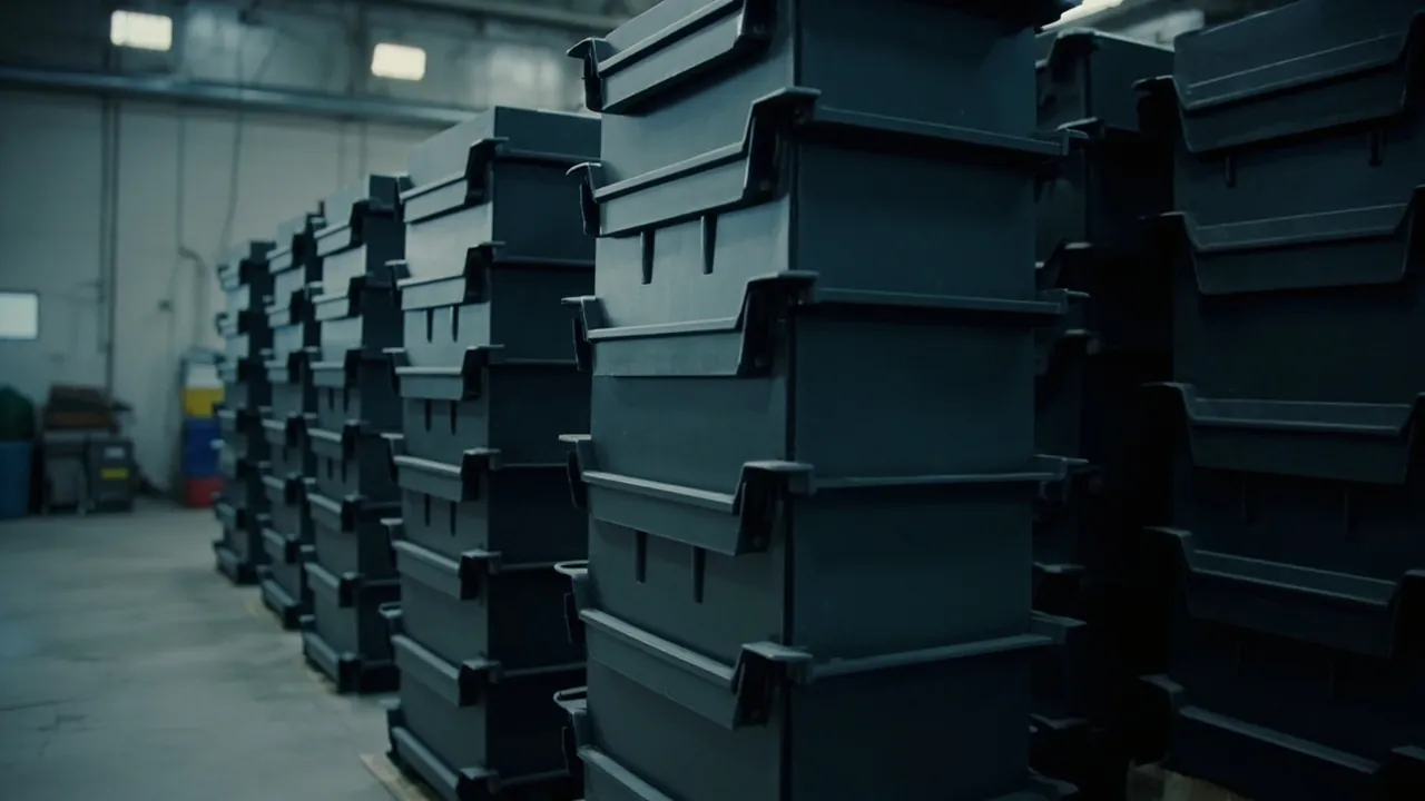
The key point first: stacking height is not a product specification. It is a conclusion about a duty condition. The same stacking system that sits safely three layers high beside a warehouse rack can fail at two layers in the bed of a pickup on a rough road. Four layers at normal indoor temperature may be fine, while three layers in a vehicle cab in summer can sink because the material softens. So the correct answer always has three parts: under what load, under what conditions, and with what restraint — and within that combination, no more than a stated number of layers. Any answer that gives a single number, whether from a catalogue or a verbal assurance, has no engineering value.
The second idea to establish is that stacking failures are rarely caused by crushing. They are overwhelmingly caused by sliding, tipping and separation. When a stack is at rest, vertical load is calculable, verifiable and can be given a margin. Lateral load comes from vehicle acceleration and braking, cornering forces, ground irregularity and handling impacts, and its magnitude usually exceeds static gravity while being much harder to cover by simple calculation. This means the primary reason to limit stacking height is not that the bottom box cannot take the weight. It is that the whole stack will not stay upright. A programme that runs a stacking load test but skips tipping and sliding verification has only verified half the problem.
This article is written for procurement, equipment and safety managers who configure stacked storage systems. It covers six settings: construction crews, warehouse and logistics, vehicle transport, camper and off-road conversion, workshop turnaround and home garage. It works through three questions: what determines the height, how stability is tested, and what safety rules must be followed in use. It provides the quantitative relationship between centre of gravity and resistance to tipping, methods and criteria for three categories of stability test, four rapid field checks, three experience-based height limits and the reasoning behind them, height guidance by setting, an explanation of restraint options, and a ten-point safety rule set plus a procurement checklist that can be posted on a wall. It closes with eight FAQ entries.
Contents
- The key point: stacking height is a duty conclusion, not a product specification
- Five variables that set the height: weight, centre of gravity, contact area, restraint and environment
- Centre of gravity and tipping: turning "higher is riskier" into a number
- Stability test one: how to run a tipping test and how to write the criteria
- Stability test two: sliding and vibration testing
- Stability test three: stacking load and high-temperature creep
- Four rapid checks you can do on site
- Three experience-based height limits and the reasoning behind them
- Height guidance by setting: site, warehouse, vehicle, camper and home
- Restraint and securing: straps, racking, frames and pallets
- Ten hard safety rules for use
- Common mistakes and how typical incidents develop
- Procurement and acceptance: a checklist for stacking systems
- Frequently asked questions
- Conclusion and related reading
The key point: stacking height is a duty conclusion, not a product specification
Three independent limits apply at once, and whichever is reached first becomes the real constraint.
Limit one: structural capacity. How much sustained load the bottom box can carry without permanent deformation that affects function. This depends on structure, material, temperature and duration. The critical point is that this is a creep problem rather than a strength problem. Plastic deforms slowly under sustained load, so a load that holds at room temperature can cause sagging after long storage in a vehicle cab in summer.
Limit two: overall stability. The ability of the stack to resist sliding and tipping under lateral load. This limit is strongly related to height: the taller the stack, the higher the centre of gravity, and the greater the overturning moment produced by the same lateral force. This is the focus of the article and the limit most often overlooked.
Limit three: access and handling. Even when structure and stability are satisfied, a tall stack makes retrieval difficult and handling dangerous. Once retrieving one layer requires moving everything above it, users will simply break the stack apart, and the system design stops working.
The correct form of statement is therefore: "safe at a uniformly distributed load of X kg, at normal temperature, three layers high, at rest, with the stack reliably restrained." That sentence carries four conditions — load, temperature, layer count and restraint — and removing any one invalidates the conclusion. Procurement should require the supplier to answer in that form rather than supplying a bare number.
One further misconception needs clearing up: being able to stack is not the same as stacking safely. Two flat-bottomed wooden boxes placed one on top of the other can be stacked, but there is no geometric constraint between them, only friction and gravity, so under acceleration the upper box can slide off as a unit. A genuine stacking system creates a geometric constraint between upper and lower bodies — interlocking bosses and recesses, dovetail features, locating steps or rail locks — so that lateral displacement is absorbed by the structure itself. Interlock forms and mechanics are covered in our article on what stacked toolbox design achieves.
Five variables that set the height: weight, centre of gravity, contact area, restraint and environment
A usable height recommendation requires all five to be assessed together. They interact and partly compensate for each other, so a strong performance on one allows a little more height while a weak performance on another forces a reduction or added restraint.
Variable one: unit and total weight. The most direct. The load on the bottom box equals the total weight of everything above it, not the weight of one box. Unit weight also determines whether handling is feasible: a box that exceeds comfortable two-person carrying weight will end up at the bottom or top of the stack in practice, whatever the structure can take.
Variable two: centre of gravity height and eccentricity. A lower centre of gravity, closer to the geometric centre of the stack, resists tipping better. Two common mistakes raise the centre of gravity or create eccentricity: putting the heaviest box on top, and concentrating heavy boxes on one side. The correct rule is simple — heavy at the bottom, light at the top, and keep the base footprint of successive layers as similar as possible so that no layer overhangs.
Variable three: contact area and interlock depth. A larger contact area and deeper engagement resist sliding better. The useful indicator is the ratio of base footprint to height. A narrow, tall stack tips more readily; a wide, low stack is more stable. A rough experience-based guide is that when total stack height exceeds twice the shorter side of the base, additional securing should be considered, subject to the actual load and conditions.
Variable four: restraint. Whether straps are used, whether they are applied correctly, and whether racking or a frame is present directly determine the permissible height. Straps turn an assembly of parts into a single body, and a single body is far more stable than an assembly. Adding correct restraint to a three-layer stack widens the acceptable road speed, surface quality and cornering radius considerably.
Variable five: environment. Temperature affects stiffness and creep, vibration loosens fixings and wears interlocks, humidity affects weight through moisture uptake and corrodes metal parts, and floor flatness affects initial stability. Note in particular that a closed vehicle body in summer can reach temperatures far above ambient, at which point long-term load capacity falls markedly, as discussed in our article on heat deformation of toolboxes kept in vehicles.
| Variable | Direction of effect | Improvement measure | Typical risk |
|---|---|---|---|
| --- | --- | --- | --- |
| Unit and total weight | More weight, fewer layers | Control unit loading, heavy items at the bottom | Creep sagging in the base |
| Centre of gravity and eccentricity | Higher centre of gravity, more tipping | Heavy low, sizes matched | Lateral toppling |
| Contact area and interlock | Small contact or shallow engagement slides | Use the same model, choose deeper engagement | Upper layer sliding out |
| Restraint | More reliable restraint, more height allowed | Ratchet straps, frames, racking | Forward surge under braking |
| Environment | Heat and vibration reduce margins | Avoid heat, damp vibration, shorten inspection interval | High-temperature sag, loosened fixings |
Centre of gravity and tipping: turning "higher is riskier" into a number
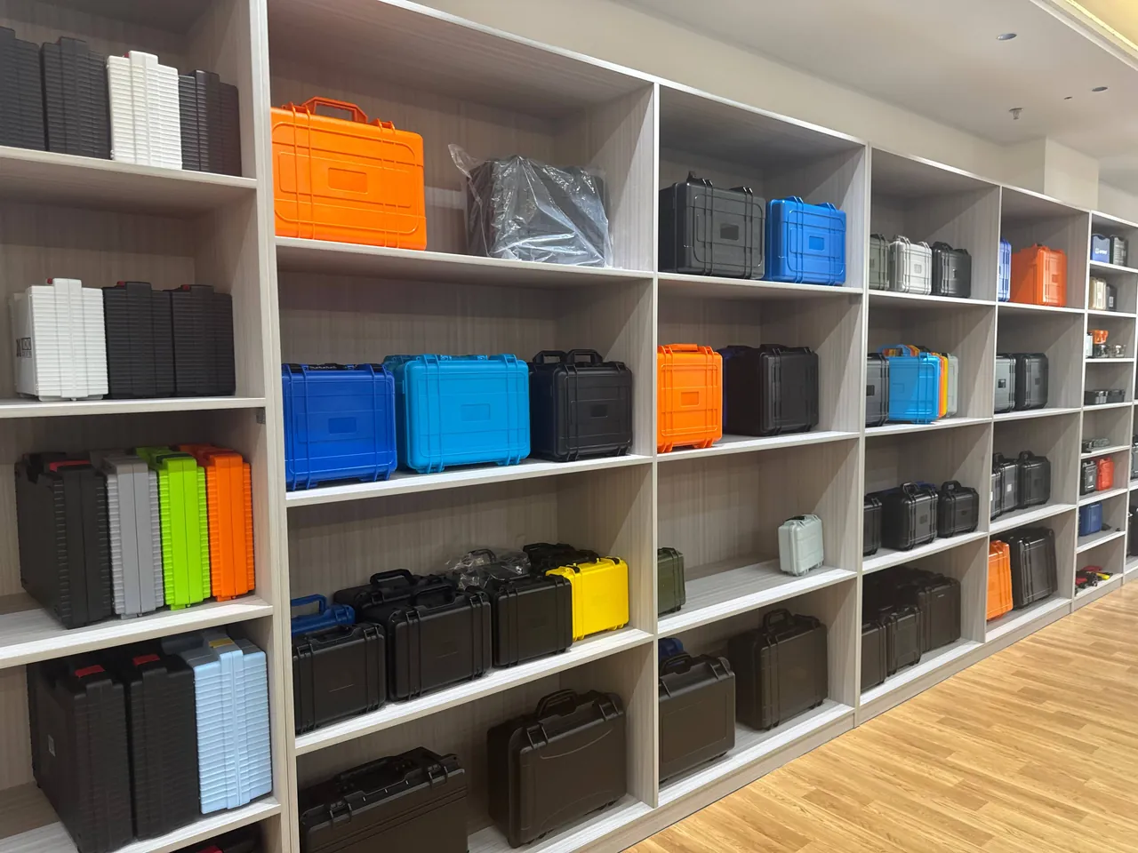
This section gives a simplified model that is good enough for field judgement.
The basic relationship: tipping occurs when the overturning moment exceeds the stabilising moment. The overturning moment is the lateral force multiplied by the height at which it acts. The lateral force comes from inertia under braking, acceleration and cornering, or from external impact and wind. The stabilising moment is the total weight multiplied by the horizontal distance from the centre of gravity to the tipping pivot. For a rectangular stack the pivot is normally the bottom edge nearest the direction of the force, and the worst-case horizontal distance from the centre-of-gravity line to that pivot equals half the base dimension.
This yields a very useful simplified criterion. Tipping begins when the lateral acceleration, expressed as a multiple of gravitational acceleration, exceeds half the base dimension divided by the height of the centre of gravity.
The value of this criterion is that it turns "higher is riskier" into something you can estimate in your head. Take an example, with the numbers illustrative only. Suppose the shorter side of the base is 0.4 m and the stack is 1.2 m tall with the centre of gravity at about half that height, 0.6 m. The critical lateral acceleration is then roughly 0.4 divided by two, divided by 0.6, or about 0.33 g. That means the stack will tip at a lateral acceleration of around 0.33 g if it is not restrained at all. Emergency braking and cornering in ordinary road driving can approach or exceed that figure, which is why an unrestrained tall stack is almost certain to fail on the road.
Three conclusions follow directly. First, lowering the centre of gravity is more effective than reducing the number of layers, because the critical value is inversely proportional to centre-of-gravity height. Putting the heaviest box at the bottom often improves stability without removing a layer. Second, enlarging the base is more effective than adding weight, because the stabilising moment is proportional to base dimension and to weight — but added weight also increases creep load on the base, while a larger base does not. Third, restraint works by converting discrete units into a single rigid body. Once restraint is reliable, the stack is no longer several boxes that can slide relative to each other but one body, and the failure mode changes from layer-by-layer ejection to whole-body displacement, which the restraint points can directly control. That is the fundamental reason straps are more reliable than trying to increase friction between layers.
Note that the model above is a statically simplified one. It does not account for floor slope, the flexibility of the stack itself, dynamic amplification of impact, or the possibility of relative sliding between layers. It is a tool for judging order of magnitude and relative risk, not a substitute for testing. Verification methods are covered next.
Stability test one: how to run a tipping test and how to write the criteria
A tipping test answers one question: at what lateral force does the stack lose stability?
Method one: tilt table test. Place the stack, assembled to the target layer count and load, on a platform with adjustable tilt, increase the angle slowly until the stack becomes unstable and record the critical angle. A larger critical angle is safer. The method is intuitive, repeatable and needs no complex equipment. Its limitation is that it simulates sustained tilt, such as parking on a slope, rather than instantaneous shock such as emergency braking.
Method two: lateral force test. Apply a gradually increasing horizontal force to the upper part of the stack and record the value at instability. The criterion should be expressed as force divided by total weight, or as an equivalent acceleration, so that it links to the criterion in the previous section. In practice, the assembled stack is required not to displace or tip at an agreed lateral acceleration, with the value set by the transport duty and customer requirement — requirements for ordinary road transport and for off-road transport should differ.
Method three: slope parking simulation. For installations fixed inside vehicles, verify that the stack remains stable when parked on the maximum gradient. This is often overlooked but is entirely relevant on underground car park ramps and mountain roads.
Four things the criteria must state. First, the test load and layer count, whether fully loaded and whether uniformly distributed. Second, the critical tilt angle or critical lateral acceleration as a number, not merely a pass. Third, the failure mode — sliding, tipping or structural failure — because the consequences and the corrective action differ. Fourth, the post-test condition: whether there is permanent deformation, whether latches remain closed, whether interlock features are damaged.
One particularly practical principle is to prefer failure mode. Given two designs that both meet the stability requirement, prefer the one that slides before it tips rather than the one that tips directly, because sliding is usually gradual and detectable while tipping is sudden. This is the same logic as preferring overload deformation over overload fracture.
Stability test two: sliding and vibration testing
A tipping test answers whether the stack will fall over. Sliding and vibration testing answers whether it will shift and loosen. The two are not interchangeable.
Vibration testing. Transport vibration subjects the stack to repeated lateral and longitudinal excitation, and it causes damage in three ways: accumulated relative sliding between layers, wear of interlock features increasing clearance, and loosening of fixings and straps. Common test approaches follow the vibration methods of MIL-STD-810H, the transport package vibration tests of the GB/T 4857 series, and the transport simulation programmes of the ISTA series. The key parameters are the vibration level, whether expressed as an acceleration spectrum or a sinusoidal sweep range, the duration, and the comparison items before and after.
The criteria should cover: relative displacement between layers measured with reference marks or displacement sensors, change in strap tension, wear of interlock features, whether latches remain closed, and whether fatigue cracks appear. Relative displacement is the most intuitive and easiest indicator. Draw a continuous reference line across the joints of all layers before the test and measure the offset afterwards. It is simple and effective.
Shock testing. Simulates emergency braking, loading impacts and potholes. The shock test methods of the GB/T 4857 series, including horizontal impact, and braking conditions from full-vehicle validation can be used. This matters particularly for stacking systems, because shock is the most direct cause of layer ejection.
Sliding testing. Measure the horizontal force required to start relative movement between layers under load, giving an equivalent friction value. Where that value is well below the inertial force in service, the design must rely on restraint rather than friction. The industry position is clear: do not rely on friction, even when the road looks smooth. Friction coefficients are strongly affected by surface condition, moisture, dust contamination and wear, and they change over time.
| Test type | Condition simulated | Key indicator | Example criterion |
|---|---|---|---|
| --- | --- | --- | --- |
| Vibration | Road-induced excitation | Relative displacement, strap tension change | Displacement within agreed limit, fixings stay tight |
| Horizontal shock | Emergency braking, loading impact | Ejection, latch condition | No ejection, latch stays closed |
| Sliding | Cornering and acceleration | Force at onset of movement | Not below an agreed multiple of service inertial force |
| Repeated handling | Daily use | Interlock wear, clearance change | Clearance within agreed limit |
One low-cost, high-value design recommendation: interlocks are plastic against plastic, so repeated stacking and separation cause wear and clearances grow. Good design makes interlock features replaceable inserts, or uses metal or higher-hardness material at the wearing points. This is a key life measure in high-frequency professional systems and should be stated explicitly as a procurement requirement.
Stability test three: stacking load and high-temperature creep

The previous two categories cover lateral stability. This section covers vertical capacity. Both must be satisfied together.
Stacking load test. Assemble the samples to the maximum permitted layer count, load to the specified weight, hold at the specified temperature for the specified time, then unload and check for permanent deformation, failure of interlock features, whether lids still operate normally, and whether the function of the bottom box is affected.
Why temperature is essential. Plastic modulus falls as temperature rises, and sustained load produces creep. A stacking test must therefore be run at at least two temperatures, normal and elevated, with the elevated condition typically taken at 40 to 50 degrees Celsius as an experience-based figure that should follow the actual service environment, noting that the inside of a closed vehicle in summer will be hotter. Running a stacking test only at room temperature and then using the product in a summer vehicle is a classic mismatch between verification and service condition.
Why duration is essential. Creep is time-dependent, and a short test only captures early behaviour. At a minimum, verify performance over the longest continuous storage period realistically expected, which for warehouse storage may be several weeks.
Closure of the criteria. The criteria must state the maximum permitted residual deformation. Without that number the test cannot be accepted and different designs cannot be compared. State also when the measurement is taken after unloading, because plastics recover elastically and measuring immediately gives a different result from measuring after a settling period.
An example combined criterion, for reference and experience-based only:
| Condition | Normal temperature, around 23 C | Elevated temperature, around 50 C |
|---|---|---|
| --- | --- | --- |
| Layer count | Maximum permitted | Maximum permitted |
| Hold time | Longest storage cycle | Longest storage cycle |
| Residual deformation | Within agreed limit | Within agreed limit, may be relaxed slightly |
| Function | Lid operates, latch effective | Lid operates, latch effective |
| Additional | No interlock damage | No sagging or collapse |
On safety factors, a common engineering practice is to require the measured pass load of the bottom layer to be at least 1.5 times the calculated load, an experience-based figure, and to write that into the acceptance standard. The calculated load should include a dynamic factor, typically 1.5 to 2.5 for transport conditions as an experience-based range, and a temperature reduction. Detailed stacking strength calculation and capacity planning are covered in our articles on capacity planning for multi-function toolboxes and toolbox capacity calculation.
Four rapid checks you can do on site
Not every setting allows full testing. The following four checks take thirty seconds to five minutes and are suitable for routine inspection and goods-in acceptance.
Check one: lateral push test, for interlock effectiveness. Stack two empty boxes and push the upper one sideways with a foot or hand using moderate force. Watch whether it is blocked by the structure or rides up and out. Riding up means the engagement depth is insufficient or the lead-in angle is wrong, and such a box is very likely to eject on a rough road and should not be used in a tall stack.
Check two: whole-stack lift test, for vertical locking. Lift the assembled pair and shake it gently, checking whether it separates. If it does not, there is a positive lock resisting relative upward movement. If it comes apart as soon as you lift, then only gravity and geometric engagement are at work, and transport must add restraint.
Check three: base press test, for structural stiffness and load path. Turn an empty box upside down and press the centre of the base with your palm. A properly structured box sinks slightly as a whole and springs back cleanly. A weak one gives a local soft spot, and you may feel internal clips shift. This quickly screens out products that look substantial but have an unsupported base.
Check four: reference line slip test, for post-transport displacement. Once the stack is in position, draw a straight line across the joints of all layers with a marker. After transport or a period of work, check whether the line has shifted. The offset is the accumulated slip. This costs almost nothing and monitors stack stability over time, so it is well worth folding into routine inspection.
| Rapid check | Time needed | What it tests | Failure indication | Action |
|---|---|---|---|---|
| --- | --- | --- | --- | --- |
| Lateral push | 30 seconds | Interlock effectiveness | Rides up and out | Reduce layers and add restraint |
| Whole-stack lift | 30 seconds | Vertical locking | Separates on lifting | Restraint mandatory in transport |
| Base press | 30 seconds | Stiffness and load path | Local soft spot, clip movement | Limit unit weight |
| Reference line | Ongoing | Transport stability | Line offset | Shorten inspection interval, strengthen restraint |
Three experience-based height limits and the reasoning behind them
The following three boundaries are reasonably well established in industry practice and, more importantly, can be explained. They are starting points for initial judgement, and all are experience-based, so actual values should be adjusted to load, duty and verification data.
Boundary one: for one- or two-person carrying, the assembled height should not exceed the carrier's chest. Three reasons. First, visibility: above chest height it becomes hard to see the ground and what is ahead, which is particularly dangerous on stairs and thresholds. Second, centre of gravity: the carrier is forced to lean back or sideways and the load on the back and spine rises sharply. Third, consequence of dropping: the higher the stack, the greater the fall and the more likely it is to strike someone. This matters most where stairs are involved, and the practice of breaking the stack down for stairs should be written into safe working procedures rather than left to individual judgement.
Boundary two: for vehicle-borne or static storage, the centre of gravity of the stack should sit below half the shorter base dimension. This follows from the tipping criterion: critical lateral acceleration is approximately half the base width divided by centre-of-gravity height. When the centre of gravity is below half the base width, the critical value exceeds 1 g, which leaves a comfortable margin even under a 1 g lateral event. Two simple measures improve it in practice: put the heaviest units at the bottom, and keep the base footprints of successive layers similar.
Boundary three: any stack above three layers, or with a total height over one metre, should have additional securing. The reasoning is empirical: within three layers and one metre, most stacking systems hold under normal handling and short transport on interlock and self-weight alone. Beyond that, the amplification of lateral load, the human disturbance during retrieval, and the difficulty of visual judgement all rise markedly. There are three categories of securing: ratchet straps, dedicated stacking locks, and an outer frame or racking.
One important addition: these boundaries are a starting point, not an endpoint. Their function is to give a conservative default when data is missing, after which verification data and actual conditions should refine the answer. Where testing is possible, replace the experience values with data. Where it is not, take the conservative end of the range.
Height guidance by setting: site, warehouse, vehicle, camper and home
The same question has quite different answers depending on the setting.
Setting one: construction crews, mobile, dispersed, stairs. Recommended: no more than two layers for short moves on a level working area, and the stack must be broken down for any stair or scaffold access. The duty involves many tool types, grouping by trade, complex carrying routes and heavy dust. A practical configuration is a wheeled heavy-duty unit at the bottom, a standard tool unit above, and a fenced platform trolley for short horizontal moves. Numbering and inspection routines should be established, because without them a stacking system quickly degrades into a set of similar-looking boxes with unknown contents.
Setting two: warehouse and logistics, predominantly static and at scale. Recommended: do not rely on self-stacking to a great height. Place boxes on standard racking shelves with a defined load per level, or stack them on pallets and secure with stretch wrap. There are three benefits: each level has a defined load, so boxes do not carry stacking load long term; stock visibility and retrieval are better; and counting and transfer are easier. Where floor stacking is unavoidable, check floor loading pressure and the clearances required for fire escape routes and sprinklers. A simple floor pressure check: total weight, being unit weight times quantity plus pallet weight, divided by the actual contact area, noting that feet reduce real contact area well below the outline area.
Setting three: vehicle transport, pickup beds and box vans. Recommended: no more than three layers in a closed van, and always restrained; no more than two layers in an open bed, with a bed cover or dedicated tool rack. The duty includes braking inertia, cornering forces, wind load and rain in an open bed. Three general rules: always use ratchet straps rather than elastic cords; form a complete restraint triangle, because a single horizontal wrap provides almost no restraint against fore-and-aft movement; and use corner protectors between strap and box to avoid crushing the wall locally.
Setting four: camper and off-road conversion, fixed installation, long-term vibration. Recommended: a hybrid of frame mounting plus removable units, with no more than two layers within the frame. The duty involves prolonged vibration on unpaved surfaces, irregular load spaces and limited fixing points. Three specific points: keep weight low in the vehicle and near the middle of the wheelbase; add rubber damping pads between frame and box, an extremely low-cost and high-benefit measure; and use locking nuts or thread adhesive on bolts, checking the fixings before every trip.
Setting five: workshop turnaround, high retrieval frequency, horizontal movement. Recommended: no more than two layers, and prefer a fenced platform trolley or transfer cart. The duty involves frequent retrieval and short carrying distances. The central conflict here is between occupied space and retrieval convenience, so prioritise modular internal design and drawer-style access rather than chasing layer count. Related thinking appears in our article on industry applications for trolley toolboxes.
Setting six: home garage, low frequency, single user, dry. Recommended: no more than three layers, and not for heavy contents. The duty involves low frequency, light load and a dry environment. Structural risk is lowest here, but tipping risk remains, and households with children should place tall stacks against a wall or fit anti-tip devices.
| Setting | Recommended layers | Required restraint | Key risk |
|---|---|---|---|
| --- | --- | --- | --- |
| Construction crew | 2 or fewer on level ground | Fenced trolley, break down for stairs | Injury carrying on stairs |
| Warehouse | Racking per level | Defined level load or pallet and wrap | Floor overload, blocked routes |
| Vehicle transport | 3 or fewer closed, 2 or fewer open | Ratchet straps and restraint triangle | Forward surge, wind toppling |
| Camper and off-road | 2 or fewer within a frame | Fixed frame plus damping pads | Loosening from sustained vibration |
| Workshop turnaround | 2 or fewer | Fenced platform trolley | Instability, lid popping open |
| Home garage | 3 or fewer | Against a wall or anti-tip | Children climbing and toppling |
Restraint and securing: straps, racking, frames and pallets
The selection logic is to decide what needs restraining, then where, then with what.
Restraint one: ratchet straps, the most general option. Used for vehicle transport, floor stacking and temporary securing. Selection points: load rating matched to total weight with margin, webbing width so that wide webbing spreads pressure and reduces crushing of the box, ratchet mechanism quality because poor ratchets release by themselves, and end fittings that engage the vehicle's fixing points reliably. Elastic cords are strongly discouraged, because they slacken under sustained vibration and store energy that makes a break more dangerous.
Restraint two: stacking locks, a matched option. Some systems offer dedicated stacking locks that lock upper and lower bodies vertically. The advantage is fast fitting with no extra space taken. The limitation is dependence on accessories, which must not be lost. Include them in the spare parts list and agree a supply period.
Restraint three: racking, the warehouse first choice. Placing boxes on standard racking shelves is the most reliable warehouse solution: each level has a defined load, boxes do not carry stacking load long term, and retrieval is efficient. Selection points include the rated load per level, the stability of contact between shelf and base, and whether retaining lips or anti-slip mats are needed.
Restraint four: outer frame or dedicated tool rack, for vehicles and campers. A fixed frame conforms to the irregular space and boxes are mounted in or on it. Space efficiency is highest and retrieval direct, but the stack can no longer be carried away as a unit, so it suits fixed locations. Key details: rubber damping pads between frame and box, anti-loosening measures on all bolts, and a defined locating and quick-fixing interface for each box.
Restraint five: pallet plus stretch wrap, for logistics turnaround. Multiple boxes are placed on a standard pallet and secured with stretch wrap. The advantages are standardisation, compatibility with forklifts and pallet trucks, and easy counting. The limitation is that wrap alone is insufficient for a tall stack, so straps should be added.
| Restraint | Suits | Advantages | Limitations | Key requirement |
|---|---|---|---|---|
| --- | --- | --- | --- | --- |
| Ratchet straps | Vehicles, floor stacking | General, strong restraint | Needs correct routing | Restraint triangle, corner protectors |
| Stacking locks | Matched systems | Fast, no extra space | Depends on accessories | Accessories not lost, spares held |
| Racking | Warehouse | Defined level load, easy access | Occupies fixed space | Verify rated level load |
| Outer frame or rack | Vehicles, campers | Highest space efficiency | Cannot carry the stack away | Damping, anti-loosening, quick fixing |
| Pallet and wrap | Logistics turnaround | Standard, mechanised handling | Insufficient for tall stacks | Use with straps |
One principle crosses all of them: interlock provides combination and straps provide restraint, and the two are complementary rather than alternative. Doing only one puts all the risk on a single element.
Ten hard safety rules for use
The following should be transcribed into working procedures and inspection routines, not left as verbal reminders.
- Any stack above three layers or over one metre in total height must have additional securing. Do not rely on friction, even when the road looks smooth.
- Break the stack down for stairs, scaffold access or any work at height. This should be written into safe working procedures and audited.
- Put the heaviest unit at the bottom and light units at the top. This lowers the centre of gravity and reduces the handling burden during retrieval.
- Stack the same model, or strictly follow the supplier's compatibility matrix. Mixed models disrupt the load path, causing confusion at best and local overload and fracture at worst.
- Re-check strap tension and fixing points after every vehicle load, every long journey and every period of rough road.
- Use ratchet straps, not elastic cords; form a restraint triangle; add corner protectors where the strap contacts the box.
- Keep stacks clear of fire escape routes and maintain the required clearance from sprinkler heads. This matters particularly in warehouses.
- Inspect interlock features, hinges, latches and gaskets for wear on a schedule. Wear accumulates clearance, showing up first as movement and later as ejection.
- Never leave a stack unattended on a slope. Add chocks when parking on a gradient.
- Take the unit out of service immediately if a latch shows any tendency to self-open, or if there are cracks, base sagging or structural deformation. Structural damage cannot be solved with temporary reinforcement.
Folding these ten rules into the daily inspection sheet adds almost no labour. The important point is that safety rules create value by being followed, not by being written down, so the three items that bear most directly on safety — securing, breaking down for stairs, and latch condition — should be set as pre-shift checks.
Common mistakes and how typical incidents develop
Mistake one: treating "it stacks" as "it is a stacking design." Two flat-bottomed boxes placed together only add weight; there is no geometric constraint, and under braking they will slide. The key to a stacking design is the geometric constraint between bodies, not the ability to place one on another.
Mistake two: testing stacking load only, with no tipping or sliding verification. This verifies half the problem. Failures are overwhelmingly lateral, so tipping, shock and vibration testing rank alongside stacking load testing.
Mistake three: stacking so high that users dismantle the system. Once a stack reaches four layers, retrieving anything from the bottom requires moving everything above, and users soon break it up, wasting every structural advantage. In practice the value of a stacking system typically peaks between two and four layers, and marginal benefit falls quickly beyond that, an experience-based observation that depends on unit weight and ergonomics.
Mistake four: mixing models. The small feet of an upper box press on the unsupported centre of the lower lid, deforming it, defeating the seal and sometimes cracking it. Where different sizes must be combined, use the supplier's dedicated adapter plate or top tray.
Mistake five: incorrect strap routing. The most common error is a single horizontal wrap around the top of the stack, which provides essentially no restraint against forward movement. The correct method is to run the strap diagonally from one side to a fixing point and repeat from the other side to form an X or triangle.
Mistake six: ignoring temperature. A closed vehicle in summer runs far hotter than ambient, reducing stiffness and accelerating creep. For long summer journeys, reduce the stack by one layer or spread the load onto racking.
Incident pattern one: forward surge under braking. The stack or its upper part slides forward. Root cause: no longitudinal restraint. Countermeasure: restraint triangle with ratchet straps. Incident pattern two: toppling on a corner. The stack falls outward through the corner. Root cause: high centre of gravity or narrow base. Countermeasure: lower the centre of gravity, enlarge the base, reduce layers. Incident pattern three: loosening from sustained vibration. Straps slacken, bolts fatigue, interlocks wear. Root cause: no damping or anti-loosening provision. Countermeasure: rubber damping pads and locking nuts. Incident pattern four: high-temperature sag. The bottom box develops permanent deformation after months. Root cause: creep not included in verification. Countermeasure: elevated-temperature stacking test and a safety margin.
Procurement and acceptance: a checklist for stacking systems
| No. | Check item | Specific requirement | Verification method |
|---|---|---|---|
| --- | --- | --- | --- |
| 1 | Interlock depth and lead-in | Deep enough engagement with a lead-in chamfer | Lateral push test: no riding up |
| 2 | Vertical locking | A lock resisting relative displacement | Whole-stack lift: does not separate |
| 3 | Stacking strength | Bottom pass load at least 1.5 times calculated load | Stacking test report including temperature and duration |
| 4 | Overturning resistance | Critical lateral acceleration or tilt angle stated | Tipping or lateral force test data |
| 5 | Sliding and vibration | Relative displacement controlled after vibration and shock | Reference line or displacement measurement |
| 6 | Load path | Upper load passes through walls, not the lid centre | Visual check plus lid deformation under load |
| 7 | Compatibility rules | Same model, or stacking to a compatibility matrix | Supplier stacking compatibility table |
| 8 | Fixing interfaces | Defined strap grooves, corner protectors, frame interfaces | Trial fit in vehicle or simulated carrier |
| 9 | Height limit marking | Permanent marking and instructions on the box | Visual check, consistency with the manual |
| 10 | Spares and expansion | Interlocks replaceable, model continuity committed | Supply period and parts list in the contract |
Three contractual suggestions. First, write the maximum stacking layer count into the usage instructions and have the supplier apply a permanent marking to the box, because many incidents stem from users assuming the stack can be extended indefinitely. Second, commit the supply period for the model, because once a stacking system loses one unit the whole set becomes difficult to complete. Third, for volume projects run a pilot combination of six units in real conditions for a month before releasing the order. In volume supply JUNZHJIA typically recommends a pilot, feedback, release sequence and writes the stacking combination rules, numbering scheme and spare parts list into the technical protocol in one pass.
Frequently asked questions
Q: How many layers can a stackable toolbox actually take? Is there a universal number? A: There is no universal number, because layer count is a duty conclusion determined by load, temperature, restraint and conditions together. That said, a set of practical defaults is a reasonable starting point. At normal indoor temperature, in static storage, with no significant lateral load and controlled unit weight, roughly 10 to 15 kg or less as an experience-based figure, three layers is usually a safe default. Four layers requires confirmation of the long-term capacity of the bottom layer and its behaviour at elevated temperature. Above four layers, additional structure or securing is mandatory. Where transport is involved, three layers or fewer in a closed van with mandatory restraint, and two layers or fewer in an open bed with a bed cover or dedicated tool rack. These three statements are conservative defaults for use when data is missing; they are not the capability limit of the product. The right approach is to request three items from the supplier — a stacking test report including temperature and duration, tipping or lateral force test data, and the stacking compatibility matrix — and then work back to a permitted layer count from your own load and duty. One practical limit is often overlooked: once a stack reaches four layers, retrieving anything from the bottom requires moving everything above it, so even where the structure allows the height, usability pushes users to break the system up. That is why industry experience puts the practical value of a stacking system at its peak between two and four layers. One final reminder: any stack above three layers or over one metre in total height should have additional securing.
Q: Why is a stacked protective case more likely to topple than to be crushed? Which risk is greater? A: Because failure is overwhelmingly lateral rather than vertical, which is exactly why a stacking load test alone is not sufficient. The reason is straightforward. At rest, vertical load is calculable, stable and can be given a margin, so as long as the structure is sound, the material is right and temperature and time are controlled, vertical failure can be managed effectively. Lateral load, by contrast, comes from vehicle acceleration and braking, cornering forces, ground irregularity and handling impacts, and its magnitude usually exceeds static gravity while being far harder to cover by simple calculation. A simplified criterion makes this intuitive: tipping begins when lateral acceleration, expressed as a multiple of g, exceeds half the base dimension divided by the height of the centre of gravity. Take a base shorter side of 0.4 m, a total height of 1.2 m and a centre of gravity at about 0.6 m. The critical lateral acceleration is around 0.33 g, and emergency braking or cornering in ordinary road driving can approach or exceed that. So an unrestrained tall stack is almost certain to fail on the road. On relative risk, toppling is generally more dangerous than crushing, because it is sudden and unannounced and its consequences point directly at personal safety: impact injuries, scattered contents and secondary incidents. Creep sagging from stacking load, by contrast, is gradual and visible. Two countermeasures follow. First, lower the centre of gravity and enlarge the base, which is more effective than simply removing layers. Second, restrain, because restraint converts discrete units into a single body and changes the failure mode from layer-by-layer ejection to whole-body displacement, which the restraint points can directly control.
Q: How much difference do straps actually make? If the interlock is good enough, can I skip them? A: They make a very large difference, and straps and interlocks are complementary rather than interchangeable. In one sentence: interlock provides combination, straps provide restraint. Interlock features such as bosses and recesses, dovetails, locating steps and stacking locks determine whether boxes can be joined into one body and resist relative lateral sliding, and they rely on geometric engagement and friction. What interlock cannot do is resist whole-body displacement, or guarantee that no layer ejects under violent shock. Straps address exactly that by tying the whole stack to fixed points on the vehicle or the ground so it cannot move as a whole either longitudinally or laterally. From an engineering perspective, the biggest change straps bring is a change of failure mode. Without restraint, failure is layer-by-layer ejection, and every layer must resist inertia independently, so more layers means more risk. With restraint, failure becomes whole-body displacement, which only has to be resisted once and can be controlled directly by the strength of the restraint points. That is why straps are more reliable than adding friction between layers. Three common mistakes should be avoided: using elastic cords instead of ratchet straps, since elastic cords slacken under sustained vibration and store energy that makes failure more dangerous; wrapping a single horizontal loop around the top, which provides almost no restraint against fore-and-aft movement; and omitting corner protectors, so the strap crushes the wall locally and may affect sealing. The correct method is a ratchet strap routed diagonally from one side to a fixing point and repeated from the other side to form an X or triangle, with corner protectors at the contact points, and a tension check after every vehicle load and every long journey.
Q: How can I run a simple stability check myself? What can I realistically achieve without test equipment? A: Yes, and four simple actions cover most of the risk. First, the lateral push test for interlock effectiveness: stack two empty boxes and push the upper one sideways with moderate force using a foot or hand, watching whether it is blocked by the structure or rides up and out. Riding up means the engagement depth or lead-in angle is wrong, and such a box is very likely to eject on a rough road and should not be used in a tall stack. Second, the whole-stack lift test for vertical locking: lift the pair and shake it gently, checking whether it separates. If it comes apart immediately, only gravity and geometric engagement are at work, and transport must add restraint. Third, the base press test for stiffness and load path: turn an empty box upside down and press the centre of the base with your palm. A sound box sinks slightly as a whole and springs back cleanly, while a weak one gives a local soft spot and you may feel internal clips shift, which quickly screens out products that look substantial but have an unsupported base. Fourth, the reference line slip test for transport stability: draw a straight line across the joints of all layers with a marker once the stack is in position, and check after transport or a period of work whether it has shifted. The offset is the accumulated slip. It costs almost nothing and monitors stability over time, so it is well worth adding to routine inspection. If you can go further, a simple tipping test uses an adjustable tilt platform, or blocks under one side, increasing the angle slowly and recording the point of instability, and a simple stacking test loads the stack to the maximum layer count at a slightly elevated temperature, holds it, then measures residual deformation after unloading. Both are simplified checks that indicate order of magnitude only and cannot replace a formal test report.
Q: Can different models be stacked together, for example a small box on top of a large one? A: Stacking the same model is strongly recommended, or strictly follow the supplier's compatibility matrix. There are three reasons. First, load path: with the same model, the upper load transfers evenly into the lower walls, whereas with mixed models the small feet of the upper box can land on the unsupported centre of the lower lid, deforming it, defeating the seal and sometimes cracking it. This is a direct application of the principle that load-bearing points should fall on the vertical load path. Second, interlock effectiveness: recess positions and dimensions on different models usually do not match, so the boxes appear to stack while actually touching at only one or two points and eject under a light lateral push. Third, stability: a large box on a small one creates overhang and eccentricity, while a small box on a large one is more stable but wastes space and slides easily, and in both cases the critical overturning acceleration is lower than for same-size stacking. Where different sizes genuinely need to be combined, for example a small consumables box on top of a standard unit, the correct method is to use the supplier's dedicated adapter plate or top tray rather than placing the small box directly on the large one. The stacking compatibility matrix should be listed as a mandatory document at procurement, and the permitted stacking combinations should be drawn explicitly in the product manual. One further point: mixed stacking also invalidates the maximum stacking layer marking, because that marking is normally established for same-model stacking.
Q: In a truck, will a stacked toolbox really fly out under emergency braking, and how should it be secured? A: Without restraint, flying out is a genuine risk, and it is the most common way a stacking system fails on the road. The key is to appreciate the magnitude of the inertia. A truck braking hard experiences a substantial deceleration, and the forward inertial force on the stack is proportional to its total weight. A 30 kg box under 0.5 g experiences roughly 150 N of forward force, and the heavier the stack and the more layers it has, the stronger the tendency for the upper layers to displace relative to the lower ones. Four methods secure it properly. First, use ratchet straps rather than elastic cords, because elastic cords slacken under sustained vibration and store energy that makes a break more dangerous. Second, form a restraint triangle: a single horizontal wrap around the top provides no restraint against fore-and-aft movement, so run the strap diagonally from one side to a bed fixing point and repeat from the other side to form an X or triangle. Third, use corner protectors between strap and box to avoid crushing the wall locally and deforming the sealing face. Fourth, place the stack against the cab side, where it is sheltered from airflow and is stopped by whatever is in front of it first, and use a bed cover or dedicated tool rack to confine the stack low down on fixed rails. Two further points of experience: keep the centre of gravity low by loading heavy items at the bottom, reduce layers, to three or fewer in a closed van and two or fewer in an open bed, and recheck strap tension after every long journey and every loading operation. Note again that interlock only provides combination and straps only provide restraint, so the two are complementary, and relying on one alone puts all the risk on a single element.
Q: What is easily overlooked when stacking toolboxes in a warehouse? A: In warehousing the central issues are not whether stacking is possible but floor loading, routes and retrieval efficiency, and these are the three most commonly overlooked points. First, floor loading. A concentrated long-term load can crack or deform a floor. A simple check is to calculate total weight as unit weight times quantity plus pallet weight, measure the actual contact area, noting that feet reduce real contact area well below the outline area, divide total weight by actual contact area to obtain pressure, and compare it with the permitted floor loading, which must be obtained from the facility owner or operator rather than estimated. Second, fire safety and routes. Stacks must not block fire escape routes, must maintain the required clearance from sprinkler heads, and must not obscure fire equipment. Although these fall under warehouse management, they should be considered when the configuration is planned. Third, retrieval efficiency and safety. Warehouses pursue scale efficiency rather than individual portability, so relying on self-stacking to a great height is not advisable. Instead, place boxes on standard racking shelves with a defined load per level, or stack them on pallets secured with stretch wrap. This brings three benefits: each level has a defined load so boxes do not carry stacking load long term, stock visibility and retrieval are better, and counting and transfer are easier. Fourth, temperature and creep. In an uncooled warehouse with high summer temperatures, the long-term load capacity of plastic bodies falls, so reduce the layer count or spread the load onto racking. Fifth, identification and turnover. Barcode or QR plus location numbering works well, boxes should have a large flat label area, and end faces are best because the top face is covered by the layer above. Assign fixed locations to frequently moved boxes so the stacking area does not become a source of visual confusion.
Q: Does an IP rating still hold when boxes are stacked? What should acceptance cover? A: Not necessarily, and this is an issue that arises frequently in practice but is rarely written into specifications. The reason is that an IP rating is a type test conclusion for a single unit in its as-delivered state, under IEC 60529 and GB/T 4208, and stacking introduces three variables. First, the upper load may press on a weak point of the lower lid. If the feet of the upper box land on the unsupported central area of the lower lid, the lid bows and the flange seam opens, and the rated class is lost regardless of its nominal value. The correct approach is for the upper load to pass through the lower box's walls rather than onto the centre of its lid. Second, lateral compression from straps. Over-tightening bows the side walls inward and changes how the sealing face seats, so strap tension should be set at the level that eliminates lateral displacement rather than as tight as possible. Third, water paths created by stacking. Contact faces, recesses and interlock grooves between boxes can become water traps, and if one sits near the sealing edge, capillary action can draw water toward the seal, so drainage channels or raised features are advisable. Acceptance should require four items: evidence of protection in the stacked condition rather than a single-unit report only; the sealing implementation, whether solid, foam or double, together with gasket replaceability; the stacking compatibility matrix, to prevent mixed models disrupting the load path; and the strap routing diagram with fixing interfaces. One further reminder: waterproof is not the same as moisture-proof. A fully sealed box breathes under day-night temperature swings, and accumulated internal moisture causes tools to rust. Industrial solutions commonly use a waterproof breathable membrane to equalise pressure or recommend desiccant, which matters especially for long-term outdoor stacking.
Conclusion and related reading
To return to the question: how high can you stack toolboxes? The correct answer has three layers. First, height is a duty conclusion rather than a product specification, so it must be given together with load, temperature, restraint and conditions, and an isolated number has no engineering value. Second, the binding limit is usually stability rather than strength, because failure is overwhelmingly sliding and toppling rather than crushing, so tipping, shock and vibration testing rank alongside stacking load testing. The relationship that critical lateral acceleration is approximately half the base width divided by centre-of-gravity height shows that lowering the centre of gravity and enlarging the base is more effective than simply removing layers. Third, safety comes from restraint rather than expectation: interlock provides combination, straps provide restraint, and the two are complementary. Any stack above three layers or over one metre in total height must have additional securing, and stairs always mean breaking the stack down.
Five practical recommendations for procurement and safety managers. First, write the maximum stacking layer count into the technical agreement as a requirement, and require a permanent marking and usage instruction on the box. Second, request three sets of data — a stacking test report with temperature and duration, tipping or lateral force test data, and the stacking compatibility matrix — and fold them into the acceptance file. Third, set height limits by setting, with two layers on level ground on site, three layers with restraint in a closed van, two layers in an open bed, and two layers within a frame in a camper, rather than applying one rule everywhere. Fourth, combine the reference line slip method and the ten safety rules into routine inspection, which adds almost no labour while monitoring stability over time. Fifth, run a pilot of six units for a month before releasing volume. For more on interlock forms and mechanics, see what stacked toolbox design achieves; for verification methods on load and life, see toolbox durability and load testing; and for outdoor use, see choosing a toolbox for outdoor work. JUNZHJIA can advise on stacking combinations based on the customer's load and duty conditions, and supports liner customisation, volume supply, distribution, OEM/ODM and global delivery.
Related reading