

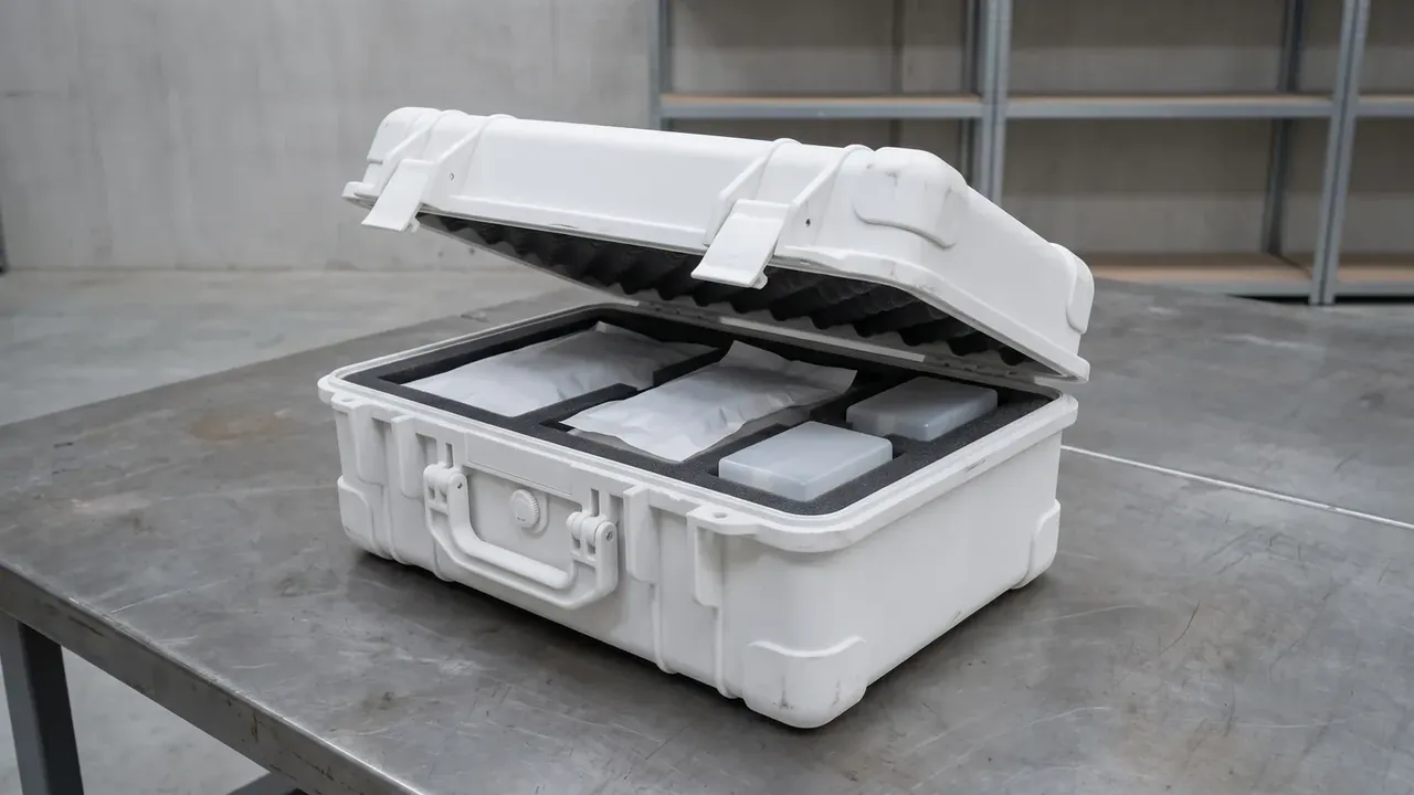
Quick answer: An Engineering Equipment Case Manufacturer is judged on a 210 s cycle, a 320-unit day and ±0.15 mm of wall tolerance, with flatness held to 0.4 mm.
Table of contents
- Line Takt at an Engineering Equipment Case Manufacturer
- Cycle Time and Cavity Count
- Wall Tolerance and Flatness Control
- Batch Traceability and Sampling Frequency
- Acceptance Values for the Buyer
- FAQ
1. Line Takt at an Engineering Equipment Case Manufacturer
Hand the same drawing to two plants and the shells can come out a millimetre apart, because takt and cooling circuits differ even when the equipment list matches. Capacity at an Engineering Equipment Case Manufacturer is not the clamp force on the nameplate; it is cycle time times available hours.
A 210 s cycle yields 411 shots in a full day. Take out tool changes, trials, purging and planned stops, and at 78% availability the figure settles near 320 units.
| Takt tier | Cycle per shot | Units per day |
|---|---|---|
| Trial | 260 s | About 260, room to tune |
| Production | 210 s | About 320, balanced |
| Compressed | 180 s | About 370, wall fails first |
Changeover belongs in the same arithmetic. One tool change a day at 45 min costs close to 7% of a 320-unit day; pull it to 20 min and the press gains a week a year.
2. Cycle Time and Cavity Count
On an Engineering Equipment Case Manufacturer line the 210 s breaks into four blocks: 4 s of injection, 12 s of packing, 180 s of cooling and 14 s of opening and ejection. Cooling holds 86% of the clock, which is why compressing a cycle always comes back to water and wall.
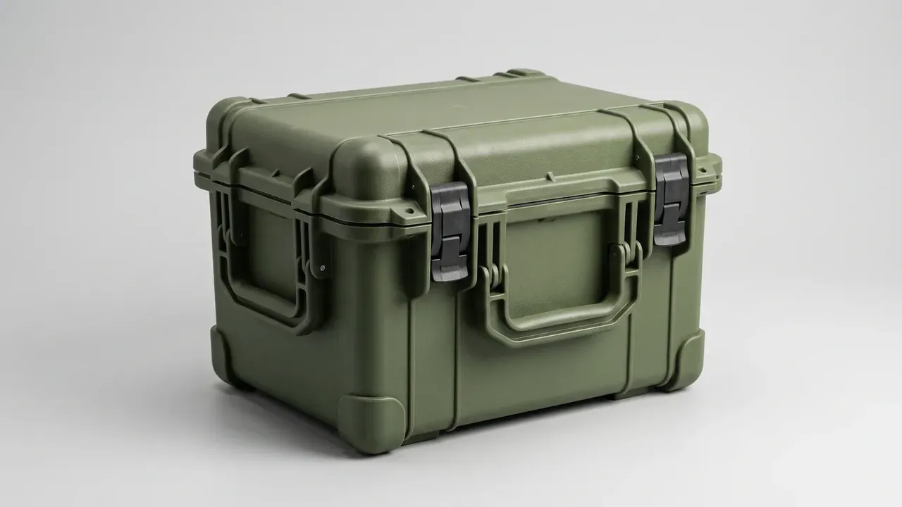
Cooling scales with the square of wall thickness. Going from 4.3 mm to 5.0 mm adds about 35% to cooling and drops the line to roughly 245 units a day; thinning to 3.8 mm saves clock but gives up drop resistance. A shell of 580 × 410 × 240 mm sits at 4.3 mm where the two ends meet.
A 580 × 410 mm face with a deep draw already needs a large press at one cavity. Two cavities need a bigger machine and cooling that cannot stay symmetrical, widening the spread between shells in one shot from 0.1 mm to 0.3 mm. An Engineering Equipment Case Manufacturer will rather run one cavity per press than ship two shells from one cycle looking different.
3. Wall Tolerance and Flatness Control
On an Engineering Equipment Case Manufacturer line a 4.3 mm nominal wall is held to ±0.15 mm, about ±3.5%. Two things keep that band: coolant in and out within 3 °C, and the pack-to-hold switch set from cavity pressure rather than a stopwatch. Flatness is the second line. The 580 × 410 mm lid has to sit within 0.4 mm, and the check waits 24 h after ejection, because a fresh part is still shrinking and reads low. It is measured on a surface plate with a feeler gauge. Groove depth is the first to go. A 0.1 mm error shifts O-ring squeeze by three points, which looks small until 4,400 openings have run and water starts at a groove corner.
4. Batch Traceability and Sampling Frequency
At an Engineering Equipment Case Manufacturer the trace code is 12 digits: date, machine, tool, shift and a running count. It is moulded into a rib inside the base rather than printed on a label, because a label does not survive five-high stacking.
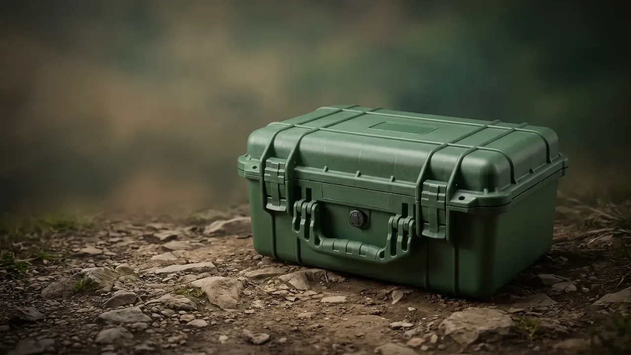
Sampling runs in three stages. One piece per tool at first-off, measured all over; five every 2 h through the run at three wall points plus flatness; five more at the end for appearance and latch travel. Colour is read to ΔE 1.5, close enough that a row of cases shows no step.
| Sampling round | Pieces taken | What is read |
|---|---|---|
| First-off | 1 per tool | Dimensions, colour, latch feel |
| In-process | 5 every 2 h | Three wall points, flatness |
| Last-off | Final 5 | Appearance, code legibility |
Data is grouped by tool number and reduced weekly into mean and range. An Engineering Equipment Case Manufacturer that only judges pass or fail per piece never sees a trend; plot the range of each five-piece group and mould-temperature drift shows in the wall first. Records are filed by batch and kept two years.
5. Acceptance Values for the Buyer
Three sets of numbers decide acceptance: 210 s against 320 units, ±0.15 mm of wall with 0.4 mm flatness, and five pieces every 2 h. The first governs delivery, the last two govern consistency.
| Tolerance reading | Feature | What happens past it |
|---|---|---|
| ±0.10 mm | Groove depth | Squeeze drifts, IP66 goes first |
| ±0.15 mm | Main wall | Weight and stack capacity move |
| 0.4 mm | Lid flatness | Gasket uneven, corners seep |
An Engineering Equipment Case Manufacturer quoting only wall thickness and cavity count leaves the rest to the acceptance clause, where flatness and colour live. A shell with a 530 × 360 × 195 mm cavity, 6.1 kg all-up, stacked 5 high and rated for 4,400 openings at IP66, is one line on a drawing and the sum of tooling, water and sampling on the floor. KeXin New Materials (Guangdong) Co., Ltd. builds the JUNZHIJIA range this way.
Takt tier is fixed at 210 s per shot and 320 units a day; push the cycle further and wall tolerance is what gets spent.
One more figure is worth checking: is the 45 min changeover real. Standard mould bases change in 30 to 120 min, so 45 sits at the quicker end; a supplier claiming 15 min should be asked whether only the insert was swapped.
Conclusion
What an Engineering Equipment Case Manufacturer delivers fits in three lines: a 210 s cycle, ±0.15 mm of wall, and five pieces every 2 h. Let one slip and the extra output is scrap produced earlier. The 6.1 kg shell, the 5-high stack and the 4,400 opening rating all hang behind them.
Related Reading
- Tooling Flow for Custom Site Cases
- Weighing Wooden Crates Against Plastic Cases
- The Usable-Volume Calculation
Related Products
- 8 Series — Gun Cases; Military Equipment Cases; Camera Equipment Cases; Drone Cases; Watch Cases; Knife Cases; First Aid Cases; Electronics Equipment Cases
- WL8-2812 PP Gun Case — model WL8-2812
- All protective cases and toolboxes: 7 series, 158 models