


Quick answer: Specifying a foam insert installation starts with three numbers — cavity clearance, vertical load and surface pressure — then runs through drop height and target g to set thickness, back into case wall and corner allowance, and closes on four acceptance figures.
Table of contents
- Three Numbers Behind Every Foam Insert Installation
- From Load to Case Wall Thickness
- Corners and Deep Pockets: Cutting Allowance
- Assembly Tolerance: Four Acceptance Numbers
- FAQ
1. Three Numbers Behind Every Foam Insert Installation
A drawing for a foam insert installation shows three views and little else. The numbers that decide whether it works never appear there: clearance around the cavity, load per unit area, and the pressure that stops the item drifting inside the case.
Clearance is quoted per side. Small parts need 5 mm; anything with a handle, lens or connector needs up to 15 mm, because the cutter also needs offset and adhesive allowance. Load is filled weight over real contact area — a 30 kg case resting on four faces puts 7.5 kg on each, which reaches the foam as hundredths of a newton per square millimetre.
| Parameter | How it is calculated | Usual range | First move when out of range |
|---|---|---|---|
| Cavity clearance | cavity side minus part outline | 5–15 mm per side | re-cut the profile, not the thickness |
| Vertical load | filled weight over contact area | 0.02–0.08 N/mm² | add contact area or change density |
| Surface pressure | clamp force over contact area | 3–8 kPa | adjust compression, not adhesive |
The third number is the one people skip. Under 3 kPa the foam touches the item without gripping it, and low-frequency vibration walks the part to the pocket floor. Above 8 kPa the lid needs the case held down to open, and case hinge loads climb.
2. From Load to Case Wall Thickness
Drop height comes first, then target g, and only then does stroke mean anything. A 1.2 m drop against a 40 g target calls for 45 mm to 50 mm of stroke; 50 mm leaves margin.
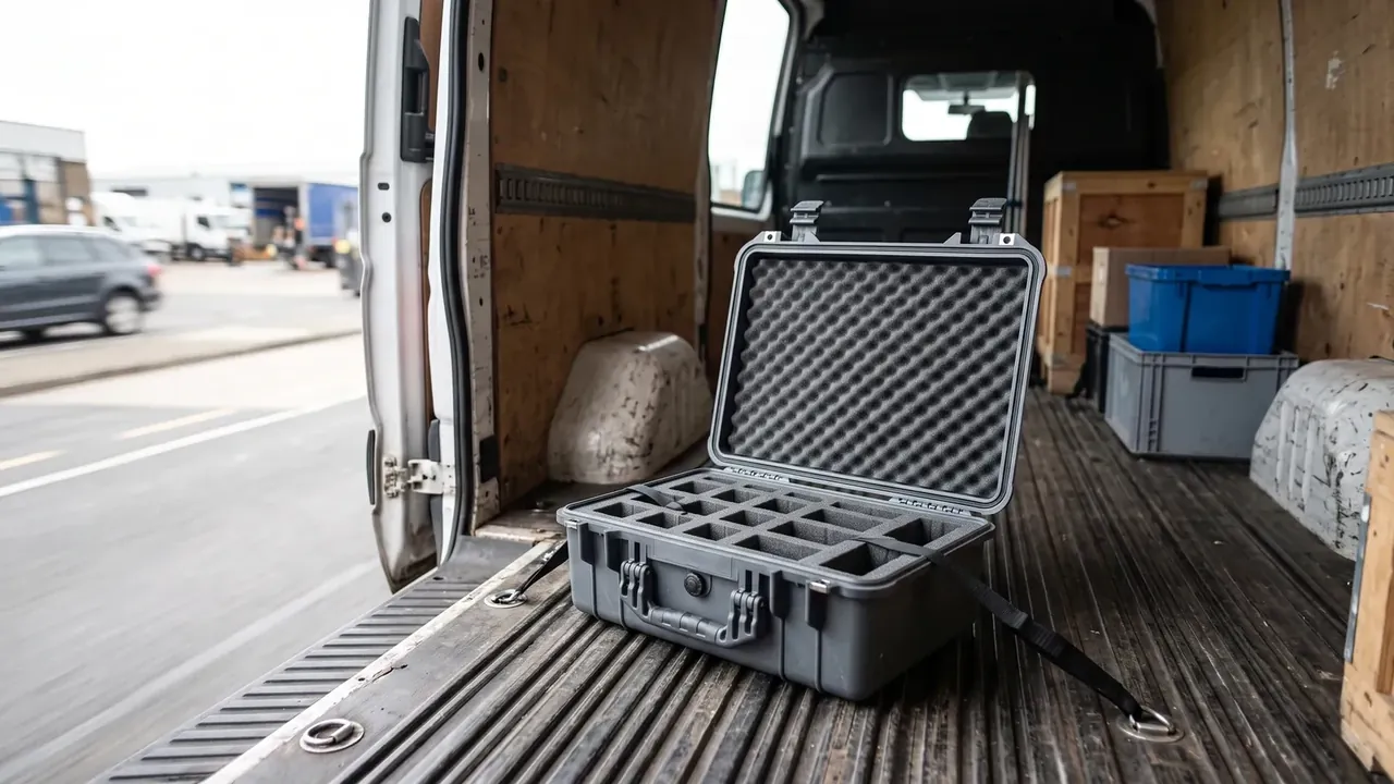
With stroke fixed, thickness can be argued. PE30 foam carries about 45 kPa at 25% compression while EVA at 60 kg/m³ reaches roughly 90 kPa, so the softer material needs more section for the same energy. That is why a 30 kg load often gets 50 mm of PE and only 35 mm of EVA, and why mixed-density drawings fail at acceptance.
Wall thickness then sits downstream. A PP case with a 500 mm cavity span, 8 mm walls and ribs at 120 mm deflects about 1.2 mm under 0.05 MPa; take the wall to 6 mm and deflection passes 2.6 mm, eating the interference the foam was meant to supply. Temperature moves the same numbers: at -20°C the modulus of PP nearly doubles, the case shell stiffens and almost all impact energy transfers into the foam. Storage at 60°C runs the other way, softening the shell so interference grows and the lid needs force. Both ends have to be checked together, since a room-temperature fit hides the weak link. The chain therefore ends not in a table but in a statement that stroke and interference hold between -20°C and 60°C.
3. Corners and Deep Pockets: Cutting Allowance
The expensive mistakes sit at the corners. Draw a right angle and the cutter cannot reach it; the pocket arrives with a radius and the part jams.
- Inside corner radius 3 mm minimum; with a 6 mm cutter, offset 3 mm and run an arc
- Pocket width 12 mm minimum, or chip clearance fails
- Depth-to-width ratio 6 at most; beyond that, two passes with chips cleared between
- Three laminated layers at most, each adhesive film counted at 0.15 mm
- Waterjet kerf compensated at 0.8 mm; thin sections reach 1.0 mm
- Routing: 18000 rpm at 3000 mm/min, top of range for PE
One hidden allowance: a pocket floor should never sit against the case wall. Leave 3 mm of foam under it, because a pocket cut to the shell puts the load on hard plastic.
4. Assembly Tolerance: Four Acceptance Numbers
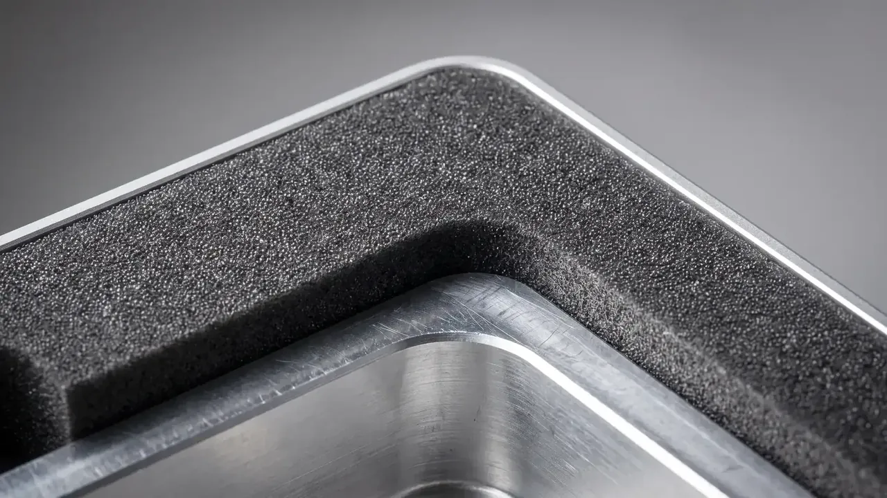
Tighter is not better. Each number governs one behaviour, and any one out of range shows up somewhere else in the case.
| Acceptance number | Target | Limit | What drifts first |
|---|---|---|---|
| Side wall gap | 0.5 mm | 1.0 mm | lateral movement, polished pocket edges |
| Top interference | 2 mm | 3 mm | lid fights the latch, preload lost |
| Base flatness | 1.0 mm | 1.5 mm | corners lift, case rocks on a bench |
| Compression ratio | 30% | 40% | rebound reserve gone, gaps in six months |
Interference and compression ratio move as a pair. At 2 mm the ratio sits near 30%, where sealing and feel work; at 3 mm it nears 40%, tighter on day one and starting the fatigue clock.
Conclusion
Specifying a foam insert installation runs from three numbers — cavity clearance, vertical load, surface pressure — through drop height and material stress to thickness, and closes on four acceptance figures. Reverse the order and the trial fit ends in a full re-cut. Whether a foam insert installation holds up depends on that chain reaching the case wall.
This article discusses only the container (case body) side of specifications and design intent, and does not cover any handling, loading or use of the contents.
Related Reading
- Three motions of foam insert installation
- How size and density are specified in custom foam inserts
- The full foam cutting process and its parameters
Related Products
- 8 Series — Gun Cases; Military Equipment Cases; Camera Equipment Cases; Drone Cases; Watch Cases; Knife Cases; First Aid Cases; Electronics Equipment Cases
- WL8-2812 PP Gun Case — model WL8-2812
- All protective cases and toolboxes: 7 series, 158 models