

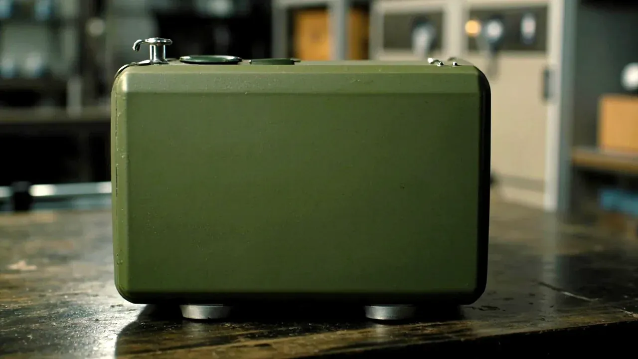
Quick answer: Cushioning and locating in a fuze packaging assembly are coupled numbers, not independent choices. Block thickness follows a static compression of 20 to 30 percent, pins run 0.3 to 0.5 mm under their grooves, saddles bear on at least 60 percent of a base, and stack load travels down four corner posts. Widen any one figure and it eats the margin of another. Drop conditions are set by the structure, and the rated level rests on a third-party test report.
Table of contents
- Cushioning design begins with a compression curve
- Pins and saddles in a fuze packaging assembly
- The stack path in a fuze packaging assembly
- Drop assumptions and the structure that answers them
- Reading the four parameter groups on one sheet
- FAQ
1. Cushioning design begins with a compression curve
Cushioning in a fuze packaging assembly is read from a compression curve, not a thickness table. Foam stays flat, then turns steep past a knee; before it is travel, after it is load transfer. Keep stacking compression before the knee; let a drop use the travel.
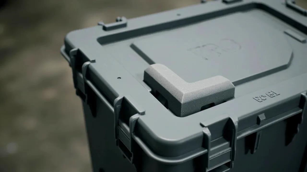
Twenty to thirty percent static compression follows. Under twenty the block separates in vibration and knocks; over thirty, half the travel is gone and the peak multiplies. Cold stiffens foam, so read the figure cold.
2. Pins and saddles in a fuze packaging assembly
Locating tolerance in a fuze packaging assembly is a pair: clearance between pin and groove, plus how fully the saddle meets the base. Too little scores the surface, too much lets a unit rotate until the pin becomes a load path.
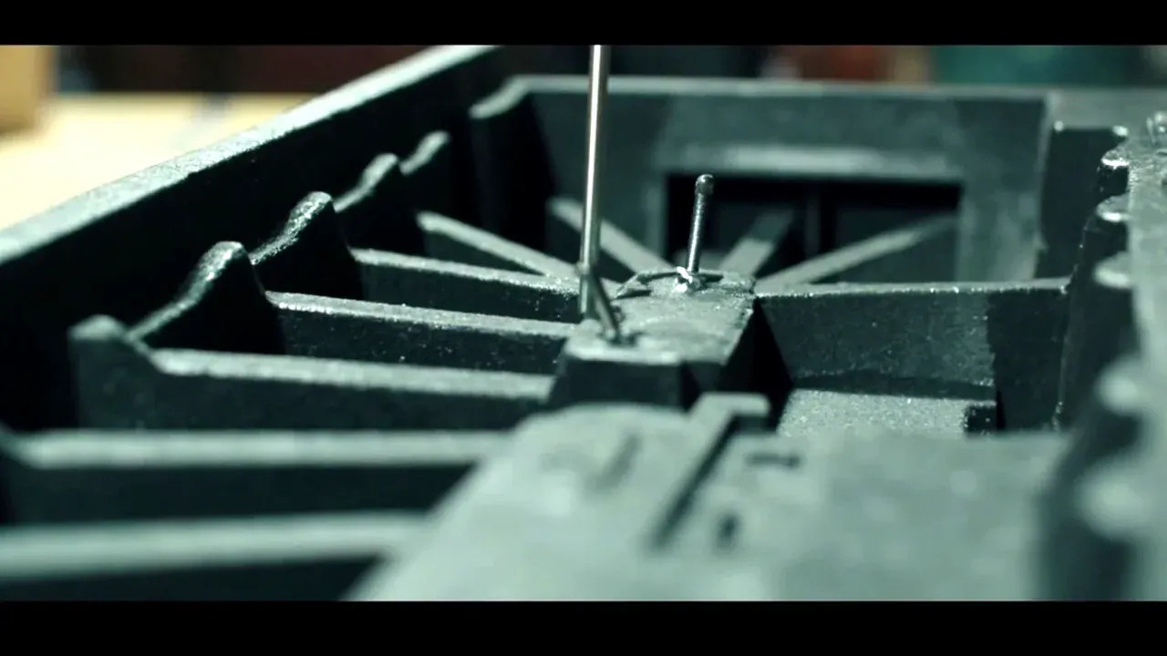
A saddle covers at least sixty percent of the base, or the rim embeds in foam and crushes. A step beneath passes load into the liner flat. Check coverage by tracing the base outline and overlaying it.
3. The stack path in a fuze packaging assembly
The weight above enters the lid, runs down the walls into four corner posts and leaves through the floor. Break the path and the force diverts into liner and cushioning, sized for shock, not months of static load.
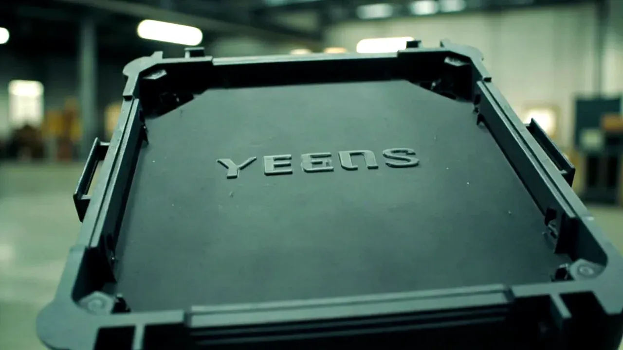
Lid ribs must line up with the posts, within ten millimetres, and the floor needs four feet equal within half a millimetre. Press an empty case on a flat plate; a rocking one has no place in a stack.
4. Drop assumptions and the structure that answers them
Severity in a fuze packaging assembly comes from three figures: drop height, landing attitude, and the freedom a unit has in its cell. Height follows packed weight, attitude takes corner and edge, freedom is closed by locating parts, not by pressing foam tighter.
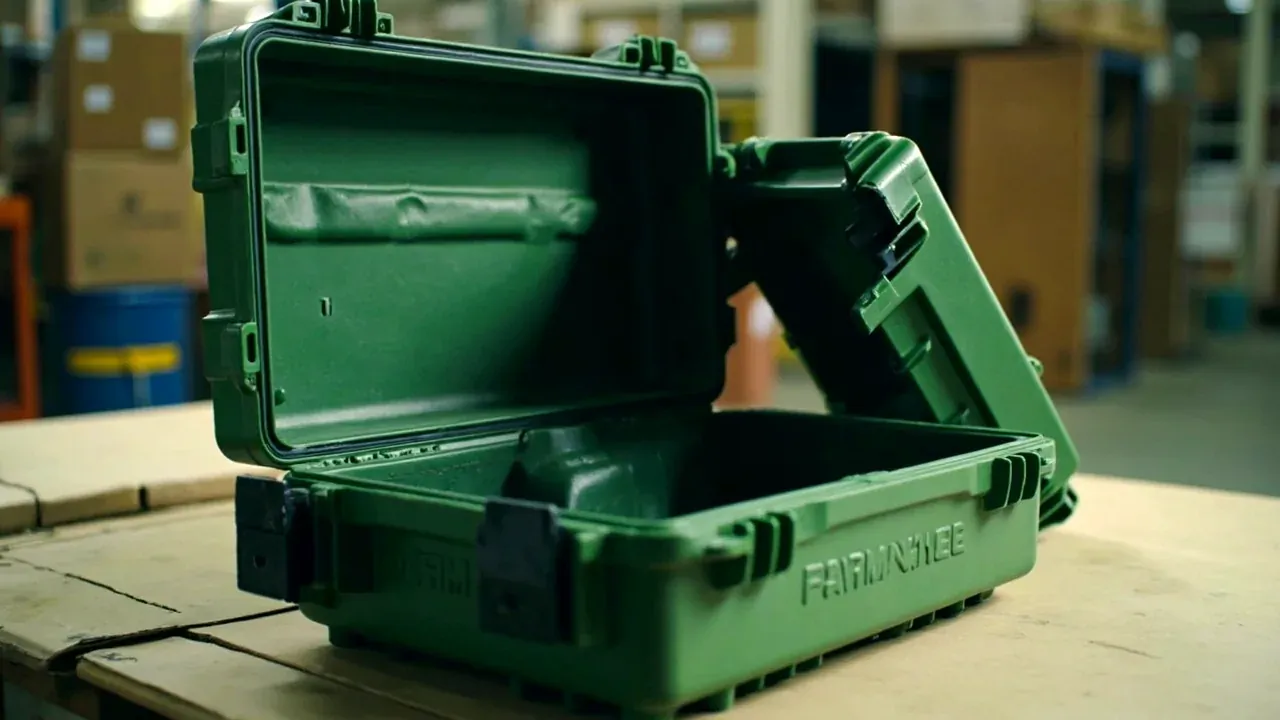
Answer in three stages: radius and thicken the corners so deflection happens in the curve; wrap a block inside each corner to turn a point into an area; double the liner there. Reverse them and a thicker corner passes the peak on. These are design assumptions; the rated level rests on a third-party report.
5. Reading the four parameter groups on one sheet
Each parameter group in a fuze packaging assembly looks sound alone and conflicts together: a thicker block eats cell space, a smaller cell pushes the pin inward. Work back from clear cell size: cell, pin, then block.
Lay the sheet out by part with design value, basis and method. Name the tool and the spot, or two people return two sets of numbers. Keep it in the lid, with last batch readings beside it.
| Part | Parameter | Design value | How it is checked |
|---|---|---|---|
| Corner block | static compression | 20 to 30 percent of original | caliper before and after load |
| Locating pin | clearance to groove | 0.3 to 0.5 mm per side | feeler gauge, half the pin at most |
| Saddle | bearing area on base | at least 60 percent | trace the outline and overlay |
| Floor posts | height at four corners | within 0.5 mm | press on a flat plate for rock |
Conclusion
Cushioning and locating in a fuze packaging assembly are coupled, so changing one sends you back to the other three. Check clear cell size, pin position and clearance, saddle bearing area, and only then block thickness. Start with thickness and the cell shrinks, the pin moves inward and the bearing area falls short. Write the figures inside the lid and measure before you judge the batch.
This article covers container-side specifications and design implications only, not the handling, loading or use of the contents.
Related Reading
- What a fuze packaging assembly is for
- Marking and compliance for shipping containers
- Cell layout and counting in small arms boxes
- Rotomolded Cases: Rotational-Moulded Shell Structure & Pro…
Related Products
- 8 Series — Gun Cases; Military Equipment Cases; Camera Equipment Cases; Drone Cases; Watch Cases; Knife Cases; First Aid Cases; Electronics Equipment Cases
- WL8-2812 PP Gun Case — model WL8-2812
- All protective cases and toolboxes: 7 series, 158 models