

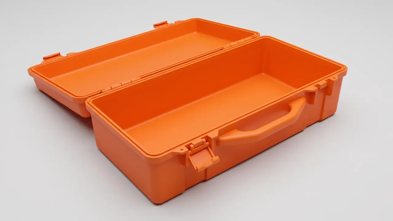
Quick answer: Write Gear Case specifications in three layers: internal size decides what fits, wall thickness and weight decide who carries it, load and stacking decide how high it goes. Push one layer and the other two send the bill.
Table of contents
- Internal Size and Divider Modules for a Gear Case
- Handle and Latch Load Points
- Wall Thickness Weight and Load
- Sealing Ratings and Test Conditions
- Stacking and Top Load Ratings
- FAQ
1. Internal Size and Divider Modules for a Gear Case
A Gear Case drawing starts from the cavity. The envelope sets van and shelf fit, the cavity sets what goes in, and the gap is wall, rib and cap. Quote the cavity at plus or minus 1.5 mm and the envelope at 2 mm: a liner 2 mm wide will not press in.
Dividers run on a 25 mm module, with 75 mm as the narrowest bay a gloved hand can reach. Depth steps in 25 mm, usually 100, 150 or 200 mm.
| Item | Written as | Tolerance | Purpose |
|---|---|---|---|
| Internal size | length by width by depth | 1.5 mm | liner cut to this |
| Outer envelope | including caps and bosses | 2 mm | van and shelf fit |
| Divider module | multiples of 25 mm | to module | 75 mm minimum bay |
| Lid depth | separate line | 1.0 mm | height of standing items |
2. Handle and Latch Load Points
The handle and latches are the only places where a Gear Case trades force with the outside, so both follow loaded weight: 700 N static at 45 kg, 350 N per strap anchor.
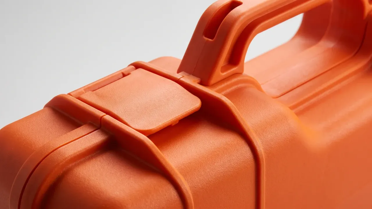
The handle root has to land on a rib, never on flat wall. At 700 N a 3.5 mm panel creeps at 40 °C and whitens within a year, so extend each end 40 mm into a vertical rib or mould a 6 mm collar.
Latches are sized from gasket reaction, not case weight. A 10 mm cord at 25 percent pushes 150 N per metre, so two latches on a 1.6 m case share 120 N each and a 350 N catch keeps 2.9 times margin. Past 1.2 m, add a third.
3. Wall Thickness Weight and Load
Thickness and load are not linear. A 3.0 mm wall gives 4.8 kg and 40 kg on the lid, 3.5 mm gives 5.9 kg and 55 kg, 4.0 mm gives 7.2 kg and 65 kg. From 3.5 to 4.0 the load rises 18 percent while weight rises 22 percent.
| Wall | Empty weight | Top load | Deflection at 300 N |
|---|---|---|---|
| 3.0 mm | 4.8 kg | 40 kg | 2.8 mm |
| 3.5 mm | 5.9 kg | 55 kg | 1.9 mm |
| 4.0 mm | 7.2 kg | 65 kg | 1.4 mm |
| 4.5 mm | 8.6 kg | 70 kg | 1.2 mm |
Every load figure needs its condition: the same Gear Case holds 55 kg on supports 400 mm apart and 38 kg at 600 mm, since deflection follows the span cubed.
Weight needs a stated basis: a 15 mm EVA liner adds 0.6 kg and wheels 1.1 kg, so 5.9 kg arrives at 7.6 kg.
4. Sealing Ratings and Test Conditions
A rating means nothing without its test conditions. Common steps are IP65 for jets and IP67 for short immersion; the difference sits in the method.
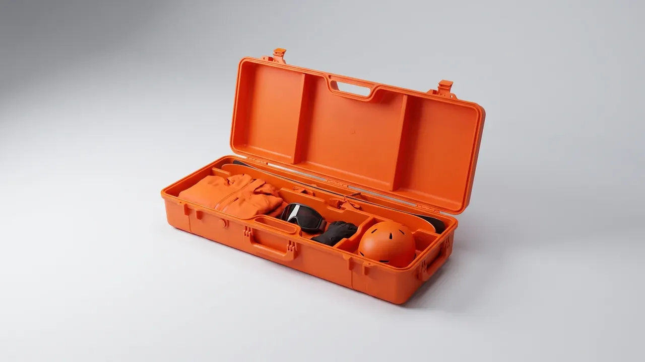
Dust follows IP6X: talc at 2 kg/m³, 2 kPa vacuum inside, eight hours, no powder in the cavity. Water follows IPX5: a 6.3 mm nozzle at 12.5 L/min from 3 m for three minutes. IPX7 is 1 m of still water for 30 min, water and shell within 5 °C.
5. Stacking and Top Load Ratings
A tier count alone is useless; state the base load and the time. Five high at 45 kg puts 180 kg on the bottom lid, and residual set after 24 h should stay under 2 mm at 40 °C, since a room test shows six tenths of the hot figure. Top load dishing is short, stacking creep is long.
State the support surface too. On 700 mm rack beams the base spans open and contact shrinks to 60 mm a side, halving the floor capacity, so a Gear Case figure without it cannot be checked.
Conclusion
Cavity, wall and load pull against each other. Fix the cavity, then the carry points, then the wall, then check stacking; skipping a step moves the cost elsewhere. Put conditions and tolerances in one table and the Gear Case specification survives.
This article discusses only the container (case body) side of specifications and design intent, and does not cover any handling, loading or use of the contents.
Related Reading
- How a gear case is built
- Gear case against four alternatives
- How protective case sizes are banded
- Writing specifications for custom foam inserts
Related Products
- 8 Series — Gun Cases; Military Equipment Cases; Camera Equipment Cases; Drone Cases; Watch Cases; Knife Cases; First Aid Cases; Electronics Equipment Cases
- WL8-2812 PP Gun Case — model WL8-2812
- All protective cases and toolboxes: 7 series, 158 models