

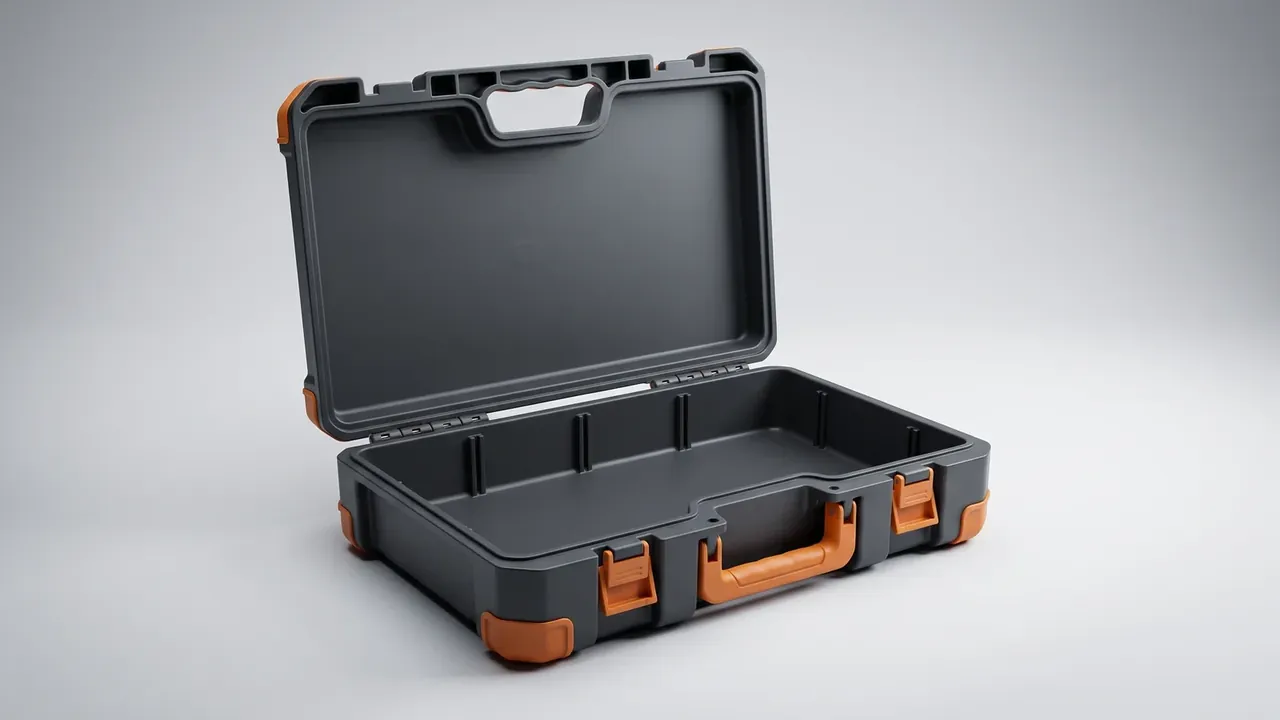
Quick answer: A hardware tool box wall is the end of a derivation, not a starting number. Work back from three loads — carry, stack and drop — fix the internal volume, match side wall and rib pitch to the span, then check pressure and drop. The 28 kg class lands at 4.5 mm base, 3.5 mm sides, 85 mm rib pitch.
Table of contents
- Where the Load Calculation Starts
- Turning Internal Volume into Outside Dimensions
- Pairing Wall Thickness with Ribs
- Checking Stack Load and Drop
- FAQ
1. Where the Load Calculation Starts
Three loads, three parts. Carry load runs through the two handle mounts: a full 28 kg hardware tool box puts about 140 N on each, a 1.5 factor while walking lifts that to 210 N. Stack load presses on the lid, where four tiers leave the bottom box carrying three more. Drop is worst: a 1.0 m corner impact reads about 40 g.
Each load owns a part: carry the bosses, stack the lid, drop the corners.
| Load class | Internal volume | Base | Side wall | Rib pitch |
|---|---|---|---|---|
| 8 kg carried | 420 by 280 by 130 | 3.0 mm | 2.6 mm | 120 mm |
| 16 kg workstation | 500 by 320 by 165 | 3.8 mm | 3.2 mm | 100 mm |
| 28 kg transfer | 560 by 350 by 190 | 4.5 mm | 3.5 mm | 85 mm |
Read the table backwards only to audit an existing hardware tool box.
2. Turning Internal Volume into Outside Dimensions
Internal volume comes first: only a tool list can dictate it.
Six steps consume the clearance, in this order:
- Measure the largest tool and add 8 mm per side for hand access
- Add wall thickness both sides, then base plus lid depth
- Add 1° of draft per 100 mm of height, about 10 mm in total
- Radius inner corners to R3, since sharp corners concentrate stress
- Allow 10% compression on the foam, or the lid will not seat
- Reserve 15 mm at the handle, or fingers will not fit
A 560 by 350 by 190 cavity becomes a 596 by 386 by 214 outline; of the 36 mm added, only 7 mm is wall.
ABS shrinks about 0.5%, so 596 mm on the part means 599 mm in steel; get the direction wrong and the first shot will not enter the slot.
3. Pairing Wall Thickness with Ribs
More wall is not more stiffness. Taking a side from 3.5 mm to 4.5 mm adds 28% weight and 12% bending strength; stiffness belongs to the ribs.
| Rib thickness | Rib height | Bending gain | Sink risk |
|---|---|---|---|
| 2.0 mm | 12 mm | 1.25 times | Low |
| 2.4 mm | 16 mm | 1.45 times | Low |
| 3.0 mm | 20 mm | 1.62 times | Medium |
| 3.0 mm | 24 mm | 1.68 times | High |
Two lines hold the pairing. Rib thickness stays under 0.7 of the wall, so a 3.5 mm side takes a 2.4 mm rib; above that a shallow sink appears opposite the rib root and paint will not hide it. Rib height stays under 8 times its thickness, so a 2.4 mm rib tops out near 19 mm.
Pitch follows a third of the span: a 560 mm cavity at 85 mm takes six ribs and lifts pressure from 620 N to 900 N; at 120 mm pitch the same wall stops at 700 N.
4. Checking Stack Load and Drop
Check bottom up: base, sides, lid, handle.
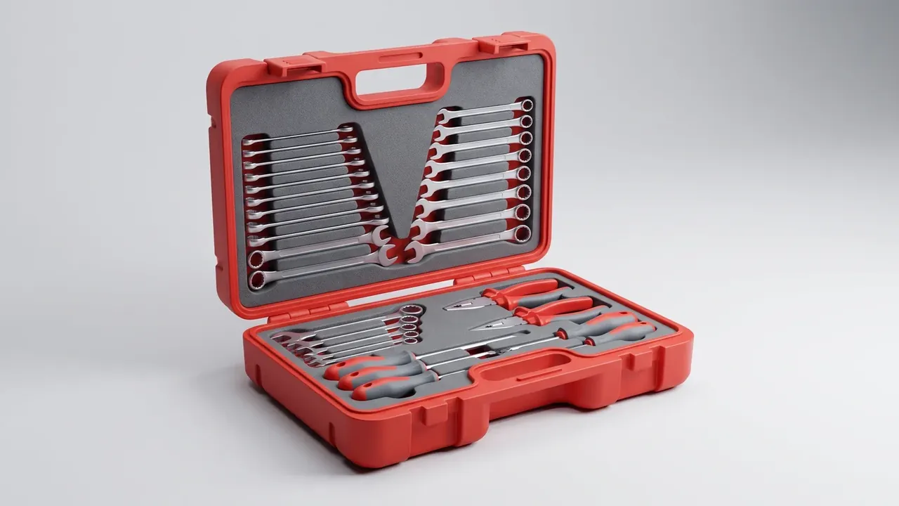
Base pressure is figured on the feet: four moulded feet of 40 by 25 mm give 4,000 mm², so 28 kg lands at 0.07 MPa, far below yield, which is why the 4.5 mm base exists for drop. At four tiers the bottom hardware tool box carries 84 kg on its lid; past 3 mm of centre deflection it touches the tools inside, so lid ribs go in or the stack drops to three. Heat matters: at 55 °C the modulus of ABS falls about 15%. The handle is checked alone: two M8 inserts at 15 N·m, 4.2 kN pull-out, three times working load. Drop testing runs 1.0 m free fall on six faces and eight corners, then checks for cracks and popped latches. Pass all four and the wall-to-rib pairing holds; fail any one and the ribs change before the wall does.
Conclusion
The wall of a hardware tool box sits at the end of the chain: load class fixes internal volume, span fixes rib pitch, ribs and wall are paired, and pressure, deflection and drop check the result. With this table at the design review, a hardware tool box drawing is far more likely to pass first time.
This article discusses only the container (case body) side of specifications and design intent, and does not cover any handling, loading or use of the contents.
Related Reading
- How hardware tool boxes are configured at workstations
- Comparing similar case bodies
- Dimension chains and cavity allocation in metal tool chests
Related Products
- 8 Series — Gun Cases; Military Equipment Cases; Camera Equipment Cases; Drone Cases; Watch Cases; Knife Cases; First Aid Cases; Electronics Equipment Cases
- WL8-2812 PP Gun Case — model WL8-2812
- All protective cases and toolboxes: 7 series, 158 models