

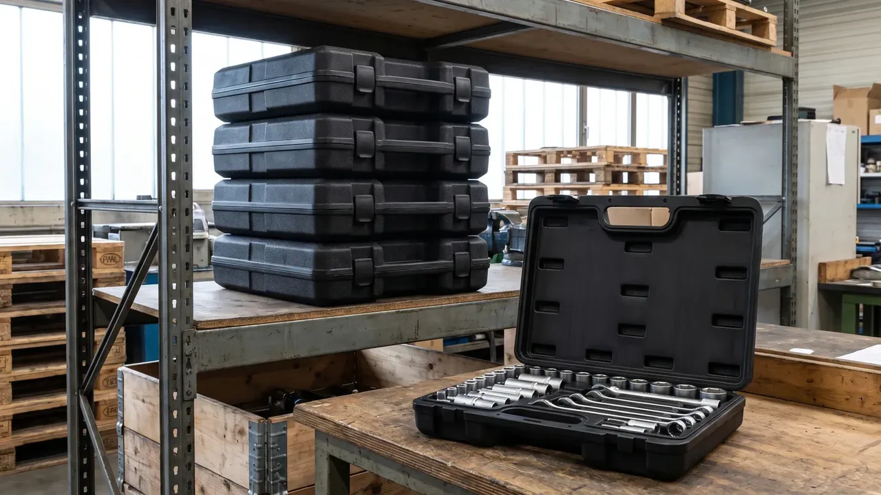
Quick answer: An Industrial coating thickness gauge tool box holds divider tilt over 70 deg under a 1.5 kg cell load, with 7.2 mm slot depth and 132 mm rib spacing.
Table of contents
- Industrial coating thickness gauge tool box slot depth
- Lid press rib spacing
- Tilt reading under single-cell offset load
- Slot mouth wear after insertion cycles
- Slot depth floor for gauge batches
- FAQ
1. Industrial coating thickness gauge tool box slot depth
Divider failure in a gauge case rarely starts with a cracked panel; a single-cell offset load turns the whole insert about the slot mouth instead. An Industrial coating thickness gauge tool box measures 490 x 360 x 170 mm outside and 430 x 300 x 115 mm inside, with a 3.5 mm wall, and 16 dividers cut the cavity into even cells.
Slot depth grades are tried one by one on the rig. One shell takes three insert grades, a 1.5 kg mass sits in the outermost cell, and tilt angle plus slot wear are logged. Once the slot is fixed for an Industrial coating thickness gauge tool box, rib spacing, lid preload and 17% gasket compression all trace back to that grade.
| Slot depth grade | Slot depth | Rib spacing | Tilt angle |
|---|---|---|---|
| Shallow | 6.0 mm | 132 mm | 66 deg |
| Reference | 7.2 mm | 132 mm | 74 deg |
| Deep | 8.4 mm | 132 mm | 78 deg |
The 7.2 mm reference lifts tilt to 74 deg, clear of 70 deg; the 6.0 mm shallow grade reaches only 66 deg and drops out first.
2. Lid press rib spacing
With the lid closed, press ribs on the inner lid hold the top edges of the 16 dividers. Rib spacing is 132 mm, matched one to one with the floor slots. On an Industrial coating thickness gauge tool box the ribs are moulded on cell centrelines, two 310 N latches share the load, and the ribs spread preload to each divider.

Ribs and slots are a top-and-bottom pair. Lid ribs brace the press rib supports, and 4800 open-close cycles must not flatten them, or the insert tops go loose. The check records shell-side rib spacing, slot depth and flange gap only. An empty 3.4 kg shell runs the closed-lid retest, both latches are logged per cycle, and one loose latch sends the unit back for rib re-matching.
3. Tilt reading under single-cell offset load
A 1.5 kg load in one cell is the worst case for this divider set. The mass presses only the outermost cell, and the angle the insert turns about the slot mouth is measured; tilt at or above 70 deg means the insert stayed put. An Industrial coating thickness gauge tool box takes the lateral force on the slot at the loaded side and locks the divider top with the rib on the other, so the two sides are not symmetric.
| Offset load grade | Cell load | Tilt angle | Slot condition |
|---|---|---|---|
| Light | 1.0 kg | 79 deg | No mark |
| Reference | 1.5 kg | 74 deg | Faint press |
| Heavy | 2.0 kg | 68 deg | Whitened mouth |
Offset load steps from 1.0 kg to 2.0 kg, and tilt falls as load rises. The reading comes from insert-top travel against the floor groove, not from visual guesswork. The 1.5 kg reference holds 74 deg; the 2.0 kg heavy grade drops to 68 deg, already past the 70 deg line.
4. Slot mouth wear after insertion cycles
Repeated insertion wears the slot mouth before the divider does. 1000 cycles is the retest count, and slot wear must stay at or below 0.2 mm / 1000 cycles. On an Industrial coating thickness gauge tool box wear is taken as the width change at the insert foot against the floor groove.
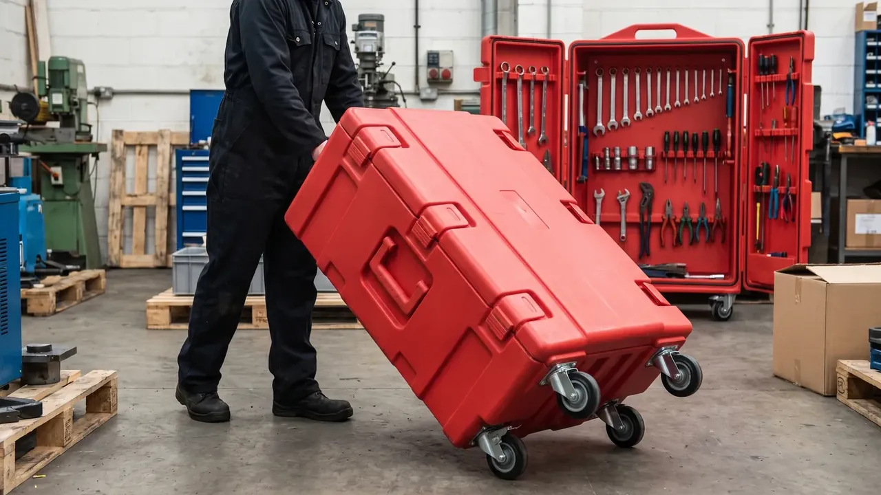
The retest follows 4800 open-close cycles, with 132 mm rib spacing and 7.2 mm slot depth left untouched, or wear cannot be traced to one source. All three insert grades run 1000 cycles, with slot wear and tilt logged together; the reference slips from 74 deg to 72 deg, still above 70 deg.
| Tilt value | First cycle | After 1000 cycles | Slot wear |
|---|---|---|---|
| Shallow grade | 66 deg | 64 deg | 0.26 mm |
| Reference grade | 74 deg | 72 deg | 0.17 mm |
| Deep grade | 78 deg | 77 deg | 0.14 mm |
The shallow grade at 0.26 mm has crossed 0.2 mm and its tilt sits at 64 deg, so both fail.
5. Slot depth floor for gauge batches
Before batch release the slot grades are gathered into one table. The slot depth floor is the grade where tilt just holds 70 deg; shallower insert sets leave the gauge case configuration table. An Industrial coating thickness gauge tool box is checked against the IP65 reference for lid sealing, and the flange gap must sit inside latch preload after 4800 cycles before 7.2 mm enters the batch card.
One record sits outside the table: if slot depth drifts shallow across a lot, tilt falls before slot wear does, and the rig tightens the grade one pass early. JUNZHIJIA shells are moulded by Ke Xin New Materials (Guangdong) Co., Ltd. to drawing, with slot, divider and rib assembled at three stations.
Set the slot shallow and the insert turns fast about the mouth; widen the ribs and the 16 divider tops lose their hold. Together they pull the offset reading down. After 1000 cycles slot wear drags tilt lower again, so only a grade holding 70 deg in both rounds can be fixed. Closed-lid retest follows, and 4800 cycles without latch looseness or flange wear lock the grade. The table for an Industrial coating thickness gauge tool box keeps one 7.2 mm row; the rest are trial values.
Conclusion
An Industrial coating thickness gauge tool box keeps divider failure out of the slot mouth by holding 7.2 mm slot, 132 mm rib spacing and 16 dividers on one grade. Tilt at or above 70 deg under 1.5 kg cell load and slot wear at or below 0.2 mm / 1000 cycles are the two hard shell-side readings. Once the slot floor is locked, open-close and insertion retests only confirm the trend has not drifted off the table.
Related Reading
- Industrial caliper gauge protective box
- Gauge block and metrology standard case
- Case wall thickness: 3 mm versus 5 mm
- Case hardware anti-corrosion finishes
Related Products
- 8 Series — Gun Cases; Military Equipment Cases; Camera Equipment Cases; Drone Cases; Watch Cases; Knife Cases; First Aid Cases; Electronics Equipment Cases
- WL8-2812 PP Gun Case — model WL8-2812
- All protective cases and toolboxes: 7 series, 158 models