

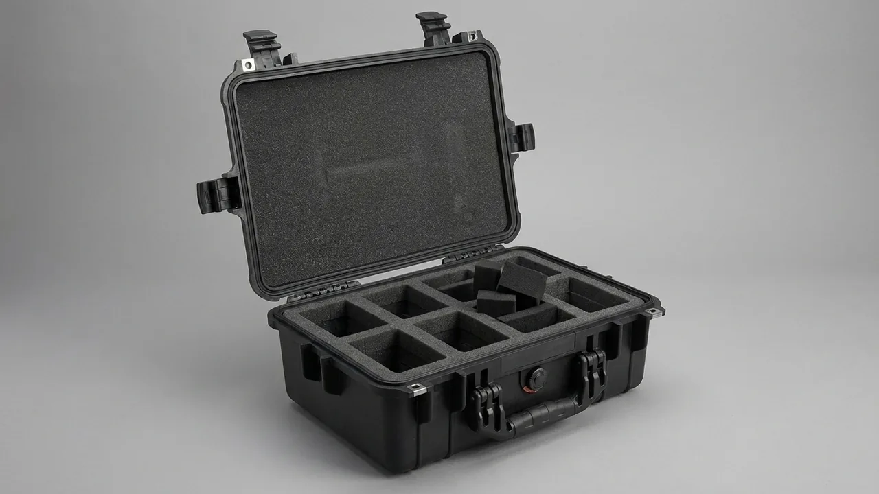
Protecting gauge blocks and metrology standards in transit is not primarily a question of case strength. The real objective is to deliver a set of micron-level length references without altering their size, flatness or wringing behavior in any way. Most metrology accidents are not breakages but invisible changes: a steel block picks up rust from residual moisture inside the lining, two neighboring blocks rub against each other and round off an edge, or an instrument is taken straight from a cold vehicle onto a calibration bench and reports a deviation larger than its tolerance because it has not reached thermal equilibrium. The defining property of this type of case is therefore a controlled-environment container, and only secondarily a carrying device.
This article is written for metrology laboratory managers, on-site calibration service providers and measuring instrument distributors. It breaks transport protection for gauge blocks, micrometers and calipers, ring gauges and plug gauges into five threads - temperature, humidity, magnetic fields, mechanical restraint and documentation - and gives acceptance criteria that can be written directly into a technical agreement.
The typical scene is familiar. A calibration technician loads gauge blocks, micrometers and ring gauges for an on-site calibration visit, or ships standards to a higher-level metrology institute for periodic verification. Once the instruments go into an ordinary toolbox, the blocks sit next to each other with nothing between them, the micrometer spindle presses against the case wall, and the ring gauges rest on the base under their own weight. On arrival nothing looks obviously wrong, yet block edges carry small nicks, micrometer anvils show scratches and ring gauge bores have suspicious marks. Under the applicable verification regulations those defects are enough to downgrade or scrap the instrument. Worse is the question of liability: without an in-case record, there is no way to establish whether the damage happened in transit or in use.
Contents
- 1. Why gauge blocks and standards demand a dedicated transport case
- 2. What actually goes in the case: block sets, instruments and standards
- 3. Micron-level accuracy: how small is an allowable defect
- 4. Temperature, vibration and magnetic fields: three environmental threats
- 5. Rust prevention: steel, ceramic and surface-treated blocks
- 6. Insert and locating structure: grouped cavities and swappable modules
- 7. Storing micrometers, calipers and dial test indicators
- 8. Support design for ring gauges and plug gauges
- 9. Shell material, sealing and desiccant management
- 10. Marking and in-case documentation under verification regulations
- 11. Transport testing and packaging validation
- 12. Use, cleaning and re-calibration discipline
- 13. Customization workflow and OEM/ODM collaboration
- 14. Acceptance checklist and common misconceptions
- Frequently Asked Questions
- Conclusion and Further Reading
1. Why gauge blocks and standards demand a dedicated transport case
What separates a measuring instrument from an ordinary tool is that its value is concentrated in a few lapped surfaces. The measuring face flatness of a gauge block is typically specified in the 0.10 to 0.30 micron range depending on grade, and the edge chamfer must not exceed about 0.1 mm and must be free of burrs. The parallelism between micrometer anvil and spindle faces is likewise specified in microns. Once such a surface takes a scratch or a dent, it cannot be restored by anything short of re-lapping, and field lapping amounts to remanufacturing.
An ordinary toolbox fails these instruments in three structural ways. First, there are no individual cavities, so parts inevitably touch, and metal-to-metal micro-motion under vibration polishes away the edges. Second, there is no humidity management, so condensation and residual hand sweat drive corrosion, and once a rust spot forms on a steel block it raises the local height of the measuring face. Third, there is no thermal buffering: thin, low-mass shells conduct daytime solar gain and vehicle temperature swings straight through to the instrument.
Traceability of the measurement chain also matters. Gauge blocks and standards normally carry a valid verification certificate, and if the instrument is damaged in transit the certificate becomes void while re-verification means shipping, queuing and waiting. For an on-site calibration provider that means service interruption. For a manufacturer it means outgoing inspection stops. Absorbing that risk with one dedicated case is the cheapest available option.
2. What actually goes in the case: block sets, instruments and standards
A single metrology case often holds several instrument families whose materials, brittleness and accuracy-critical surfaces differ completely. Classification has to come before compartmentalization.
| Instrument family | Typical material / size | Accuracy-critical surface | Protection priority |
|---|---|---|---|
| --- | --- | --- | --- |
| Gauge block set | GCr15 bearing steel, zirconia ceramic, carbide | Measuring face flatness, edges, wringing | One cavity per block, never touching |
| Block accessories and holders | Steel, stainless steel | Clamping faces, threads | Separate from blocks to avoid nicking |
| Outside micrometer | Steel frame, carbide anvils | Anvil and spindle measuring faces | Spindle retracted, faces loaded by nothing |
| Vernier / digital caliper | Stainless or carbon steel | Jaw edges, depth rod tip | Jaws closed, edges contacting nothing hard |
| Dial test indicator | Steel or aluminum body | Contact tip sphere, rack and pinion | Tip free, no sustained preload |
| Ring gauge | Steel, carbide | Internal cylinder, chamfers | Stored upright, bore not loaded |
| Plug gauge | Steel, carbide | Go and no-go working surfaces | Individual cavity, handle not bent |
| Calibration plate / square | Cast iron, granite | Working face flatness | Dedicated bay, working face unloaded |
Two decisions must be made immediately after classification. The first is block count: a common 87-piece or 122-piece set requires one cavity per block, which grows case length rapidly, so confirm with the buyer whether two cases or a two-tier tray is preferable. The second is the proportion of heavy items. Ring and plug gauges are solid steel and can weigh from several hundred grams to several kilograms each. Sharing a layer with gauge blocks creates severe asymmetric loading, so heavy items must be forced to the bottom layer and placed near the handle.
3. Micron-level accuracy: how small is an allowable defect
Converting tolerances into physical scale is the only way to judge whether a protection design is adequate. Gauge block grades follow GB/T 6093, which is identical to ISO 3650, with the usual grades being K, 0, 1, 2 and 3. Higher grades carry tighter tolerances on central length deviation and measuring face flatness.
| Nominal length | Grade K central length tolerance (reference magnitude) | Grade 0 | Grade 1 | Grade 2 |
|---|---|---|---|---|
| --- | --- | --- | --- | --- |
| 10 mm | plus or minus 0.05 micron | plus or minus 0.10 micron | plus or minus 0.20 micron | plus or minus 0.40 micron |
| 50 mm | plus or minus 0.10 micron | plus or minus 0.20 micron | plus or minus 0.40 micron | plus or minus 0.80 micron |
| 100 mm | plus or minus 0.15 micron | plus or minus 0.30 micron | plus or minus 0.60 micron | plus or minus 1.20 micron |
| 500 mm | plus or minus 0.60 micron | plus or minus 1.20 micron | plus or minus 2.40 micron | plus or minus 4.80 micron |
The figures are typical magnitudes derived from the standard; the governing values are those in the current standard and in the verification certificate. What matters is the order of magnitude. A grade 0 block of 100 mm has a tolerance of plus or minus 0.30 micron, roughly one two-hundredth of the diameter of a human hair. That explains two rules. First, any particle harder than the block material that is pressed between measuring faces can leave a dent of micron depth, already outside the grade tolerance. Second, blocks must never be stored in direct contact, because the very property that makes steel blocks wring together means that two touching blocks require a deliberate separating force, and transport vibration produces repeated microscopic sliding at that interface.
Edges are another underestimated area. Block edges participate in wringing, and the specification allows a small chamfer but no burrs. Micro-motion between metal parts gradually enlarges that chamfer until the wringing area is insufficient and blocks separate after assembly. This degradation does not cause immediate rejection, but it appears later as a failed wringing test.
4. Temperature, vibration and magnetic fields: three environmental threats
Temperature is the most tangible problem in meter transport. Steel has a coefficient of linear expansion near 11.5 x 10⁻⁶ per kelvin, so a 100 mm steel block changes length by about 1.15 microns per degree Celsius. That is the same order as the grade 1 tolerance and cannot be ignored. If a block spends the night in a 5 C vehicle and is used immediately in a 22 C laboratory, the 17 C difference corresponds to a theoretical length deviation of roughly 19 microns; even after the surface feels warm, the internal gradient needs considerably longer to disappear.
Three practical measures follow. Hold transport temperature in the general 0 to 40 C range, with 15 to 25 C recommended for precision block sets. Fit a read-back temperature recording label inside the case so the history is traceable. And let instruments stand in the working environment before going onto the bench, so the whole metal mass equalizes rather than just the surface. Soak time depends on block size and whether blocks are stacked, but a working rule is at least two hours for small blocks, four hours or more for large or case-packed sets, and longer for precision work. Environmental test methods may be referenced from MIL-STD-810H Methods 501, 502 and 507, cited here only as test methodology and not implying any military certification. The logic of controlled chamber conditions is discussed in environmental chamber component protection.
On vibration, the specific difficulty with metrology instruments is that they do not have a failure speed like rotating machinery. Damage accumulates as accuracy drift. Road transport concentrates energy between 5 and 200 Hz, and a heavy, stiff instrument case can place the system natural frequency in the 40 to 80 Hz band, which overlaps body and suspension excitation. The workable countermeasure is a soft-contact insert: add a 20 to 30 Shore A layer between the steel items and the main insert to raise damping and reduce transmissibility.
Magnetic fields are the third thread and the most frequently overlooked. Steel blocks acquire residual magnetism after magnetization, which causes two problems: they attract iron chips and abrasive particles, and the residual field affects both wringing between blocks and adhesion to a surface plate. Standards place explicit limits on residual magnetism in gauge blocks. During transport, keep the case away from loudspeakers, permanent magnetic fixtures, magnetic bases and motors. Where the buyer confirms a strong magnetic field at the process site, a high-permeability alloy layer can be added inside the shell as shielding, but the effectiveness must be measured rather than inferred from the alloy grade. For general field-sensitive designs, see ESD and field-sensitive case construction.
5. Rust prevention: steel, ceramic and surface-treated blocks
Corrosion is the most common transport defect on steel gauge blocks, and the only one that packaging design can substantially reduce. The mechanism is straightforward. Once relative humidity exceeds a threshold, an electrolyte film forms on the steel surface, and chloride and sodium ions from hand sweat raise the corrosion rate sharply. The customary control value in metrology rooms is 45 percent relative humidity or lower.
| Block material | Coefficient of expansion (reference) | Rust prevention needed | Brittleness | Protection focus |
|---|---|---|---|---|
| --- | --- | --- | --- | --- |
| GCr15 bearing steel | about 11.5 x 10⁻⁶ / K | High, anti-rust oil required | Low | Moisture, impact, magnetism |
| Zirconia ceramic | about 9 to 10 x 10-6 / K | None | High | Impact, corner chipping |
| Cemented carbide | about 5 to 6 x 10⁻⁶ / K | Low | High | Impact, individual cavities |
| Stainless steel instruments | about 16 x 10-6 / K | Depends on grade | Low | Scratches, chloride ions |
The conventional practice with steel blocks is to coat the measuring faces with a thin film of anti-rust oil or petroleum jelly after use, then put them back in the case. That creates a management subtlety: the case must accommodate both an oiled state and a degreased state, and the film thickness before packing directly affects wringing. Fix the sequence as follows: clean and oil after use, pack and transport, then wipe the film off on arrival, let the temperature equalize, and only then place the block on the calibration bench. This keeps transport protection and working condition as two separate concerns instead of one blurred activity.
Ceramic blocks need no rust protection but have a different weakness: brittleness. A concentrated impact on a corner can produce a small chip that looks minor but has already destroyed the measuring face. Ceramic blocks therefore need more cushioning clearance in the insert and must not be placed adjacent to other hard items. Carbide blocks are strong but dense, so for the same mass they occupy less volume and demand tighter cavity fit.
6. Insert and locating structure: grouped cavities and swappable modules
The insert is the only part of a metrology case that genuinely determines whether protection succeeds. A block case differs fundamentally from a general instrument case in one respect: it must achieve one item per cavity with no contact between items.
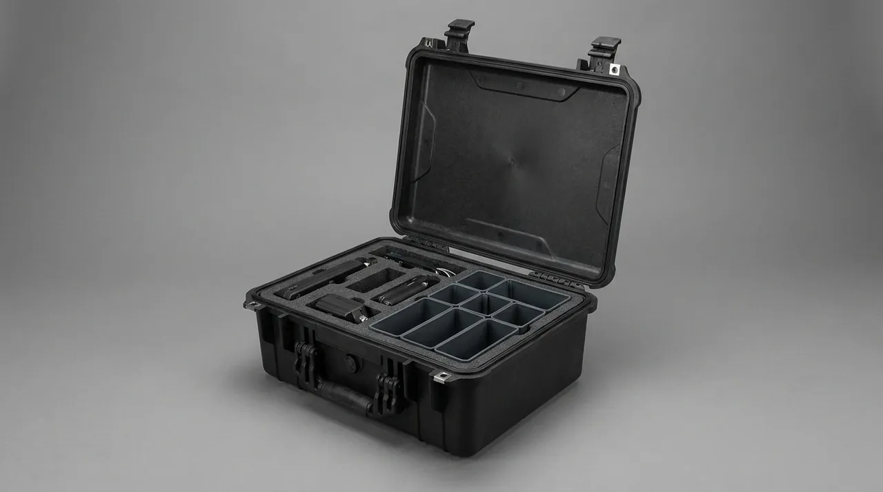
The practical measures are:
- Cut cavities by nominal size and number them. An 87-piece or 122-piece set steps through 1.005 to 100 mm, so group cavities by range (1.005 to 1.99, 2 to 9.9, 10 to 100) and mark the nominal size beside every cavity so retrieval and counting happen in one motion.
- Leave 0.3 to 0.8 mm of clearance per cavity. Blocks are thin plates; too tight a cavity scratches edges during handling, too loose permits displacement. Use EVA or low-density PE for the locating layer so it forms accurately yet grips lightly.
- Put ribs between adjacent blocks. Rib height should exceed 60 percent of block thickness so that no block can climb over a rib and touch its neighbor in transit.
- Provide an anti-rust paper position. A replaceable anti-rust paper or vapor phase corrosion inhibitor film can be inserted at the bottom of each cavity as a supplement to oiling, but confirm compatibility with the block material and the insert material first.
- Give accessories their own cavities. Block holders, scribing jaws and center jaws are steel parts with sharp corners and must be physically separated from the blocks.
For service providers using several block sets or serving multiple calibration points, a swappable module base plate works well: the plate is a standard grid and the block module, instrument module and ring gauge module are assembled as needed. This suits mobile calibration vehicles and on-site metrology stations, where one case is configured per day. Structural details of modular and removable divider systems appear in removable divider system design.
7. Storing micrometers, calipers and dial test indicators
Unlike gauge blocks, instruments are mechanisms, and their typical transport damage is deformation rather than abrasion.
Outside micrometers should go in with the spindle retracted clear of the anvil and the frame resting in a form-fit channel, with no external load on the two measuring faces. A common mistake is to drop the micrometer in vertically so the anvil presses against the case wall, which transmits vibration through the wall directly into the measuring faces. For small 0 to 25 mm micrometers, wrap the frame arc in soft EVA. For large 500 mm and above micrometers, the frame itself is heavy, so provide a rigid support cradle at the base instead of letting the insert's elastic deflection carry the whole mass.
Vernier and digital calipers are sensitive at the jaw edges and the depth rod tip. Close the jaws on packing so the edges touch nothing hard, and retract or upward-face the depth rod so it is not compressed. Digital calipers also need battery attention: remove the cell or insert an insulating tab for long storage to avoid leakage corroding the circuit. The display and keypad side should face upward with a cushioning gap.
Dial test indicators and dial gauges are high-sensitivity mechanisms, and their worst transport condition is a contact tip held under sustained preload. The tip must be free to return, and the body should be wrapped in soft material all round. In sets supplied with a stand, remove the stand and fix it separately, because its steel column will strike the indicator body under vibration. The storage logic resembles the approach in materials testing machine component protection, where mechanisms are separated from structural parts and contact tips from loaded components.
8. Support design for ring gauges and plug gauges
Ring and plug gauges are the heaviest members of a metrology case and the ones most likely to be damaged by their own weight in transit. Three failure modes dominate: the bore deforms elastically or plastically under load, the end chamfers take nicks, and the steel surfaces corrode.
Support design should follow three principles:
- Store upright with the ring wall carrying the load. A ring gauge should sit with its axis vertical so that load passes through the outer cylinder into the insert cradle, rather than being carried by the bore surface or an end face. If horizontal storage is unavoidable, provide a cradle as wide as the gauge to avoid line contact and local press marks.
- One cavity per plug gauge, handle unloaded. The handle usually attaches to the measuring head by thread or taper, and lateral force loosens that joint. Cut the cavity to the handle profile so the head hangs free.
- Fit rigid dividers between different sizes. Where several ring gauges sit close together, use rigid dividers rather than relying on foam alone, because foam loses its recovery after repeated compression.
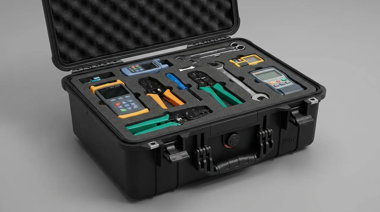
For heavy ring gauge groups, where a single item exceeds about 3 kg, also evaluate how the fully loaded case will be lifted. Plastic handles develop fatigue cracks under sustained loads above roughly 20 kg, so specify reinforced handles or add metal lifting apertures in the case sides. Load-bearing design for latches and hinges is covered in case hinge latch and seal structure, and for frequent transfers the trade-offs of wheels and telescopic handles are discussed in case wheels and trolley handle selection.
9. Shell material, sealing and desiccant management
Metrology case shells are selected on slightly different grounds than general tool cases, because weight, thermal inertia and magnetic behavior all matter.
Shell material. The common options are aluminum profile cases, injection-molded PP copolymer cases and glass-fiber reinforced PP cases. Aluminum offers good heat spreading and temperature uniformity and a professional appearance, but the metal body is magnetically permeable and profile joints create seams that depend entirely on the gasket. PP copolymer cases are one-piece molded with reliable sealing and low weight, making them the mainstream choice for volume purchasing. Glass-fiber reinforced PP is the stiffest and suits heavy ring gauge payloads.
Sealing class. Under IEC 60529 and GB/T 4208, IP54 covers dust and splashing water, which is sufficient for routine indoor transfer, urban delivery and sheltered loading. IP67 tolerates short-term immersion. The governing requirement for a metrology case is humidity control, so the ingress rating directly determines desiccant life. Specify EPDM or silicone gaskets with a one-piece molded joint. Weathering behavior and compression set of different gasket materials are compared in case seal material comparison.
Desiccant management. Size the silica gel pack at 5 to 10 percent of the internal volume and attach a humidity indicator card inside the lid. Three management points matter: saturated desiccant stops working and must be replaced on a fixed interval; every opening admits moisture, so frequently opened cases need shorter intervals; and the outside of the case should carry the last replacement date for handover. For standards kept in long-term storage, inspect and replace desiccant every three months.
Insert material. Use 30 to 45 Shore A EVA or cross-linked PE for the locating layer in closed-cell form: non-absorbent and non-shedding. Do not use plasticized PVC in direct contact with gauge blocks, because plasticizer migration leaves an organic film on the measuring face. Foam comparisons and selection methods are in case foam material comparison.
10. Marking and in-case documentation under verification regulations
A metrology case is not only a carrier; it also takes on part of the documentation and identification function, and this matters especially in the context of verification regulations.
External marking. The outside should carry the instrument name, asset number, grade, last verification date and next due date; the internal cavities should carry nominal size or instrument number. Transport markings follow GB/T 191 and GB/T 13384, covering at minimum this way up, keep dry, handle with care and the stacking limit, and it is worth adding wording such as precision measuring instrument and do not invert.
In-case documentation. Verification certificates, calibration records, temperature recording labels and packing lists belong in a gasketed waterproof document pouch fixed inside the lid, not in direct contact with blocks or instruments. Paper that absorbs moisture smears and undermines customer acceptance.
Condition record. A condition card in a fixed position inside the case should record the most recent drop or abnormal impact. Standard metrology practice is that after any abnormal impact or significant drop, an instrument must be re-verified before further use regardless of appearance. Write that rule into the instrument management procedure and state it on the case label.
Note that verification is a statutory activity conducted under the applicable JJG verification regulations for each specific instrument type, and different instruments correspond to different regulations. This article addresses packaging and transport only and does not cite verification methods or acceptance limits. Asset numbering and anti-substitution management are discussed in identifying genuine versus counterfeit cases.
11. Transport testing and packaging validation
Validate a metrology case in three stages.
The first is insert validation using dummy weights matched to the real instruments in mass and center of gravity, run through drop and vibration tests to confirm cavities do not collapse and instruments do not shift. The stiffness of the dummies should approximate the real instruments, otherwise the results are not credible. The second is whole-case validation following standard procedures for drop, random vibration, stacking and low pressure. The third is field validation, placing shock and vibration recorders in the case and recovering data from a real route.
| Test item | Reference standard | Suggested level (example) | Main observation |
|---|---|---|---|
| --- | --- | --- | --- |
| Drop | GB/T 4857.5 / ISTA | Mass-based schedule, faces edges corners once each | Insert compression at corners, block displacement |
| Random vibration | GB/T 4857.23 / ASTM D4169 | Road spectrum, 0.5 to 1 h | Rib failure, contact between items |
| Stacking | GB/T 4857.3 | 1.2 times actual stack height | Side wall deflection, instrument loading |
| Humidity exposure | GB/T 4857.9 and related | Inspect after high humidity conditioning | Internal humidity, rust spots, indicator reading |
| Low-temperature storage | Reference MIL-STD-810H Method 502 | -20 C, 24 h | Insert hardening, gasket elasticity |
Execution detail for ISTA and ASTM D4169 appears in ISTA transport testing procedure and GB/T 4857 transport packaging test points. Where packaging conditions must be written into a calibration service contract or purchasing agreement, state insert material and hardness, sealing class, desiccant provision, record-keeping method and acceptance sampling in the technical annex.
12. Use, cleaning and re-calibration discipline
The service life of an instrument case depends largely on discipline. Build the following into the metrology instrument management procedure:
- Clean measuring faces after use, remove oil and hand sweat, then apply anti-rust oil for steel blocks or simply clean ceramic blocks.
- Return each item to its numbered cavity. Do not skip cavities and do not force different sizes into one slot.
- Remove batteries from digital calipers and digital micrometers during long storage.
- Before closing the lid, confirm nothing protrudes above the insert and no accessory is left outside.
- After transport, check the humidity indicator card and temperature label first, then inspect the instruments.
- Clean the insert quarterly with a mild detergent and air dry it in the shade. Never sun-dry it or soak it in solvent.
- Record the date, route and inspection conclusion of every transfer to build an instrument history, and send instruments for verification before the due date.
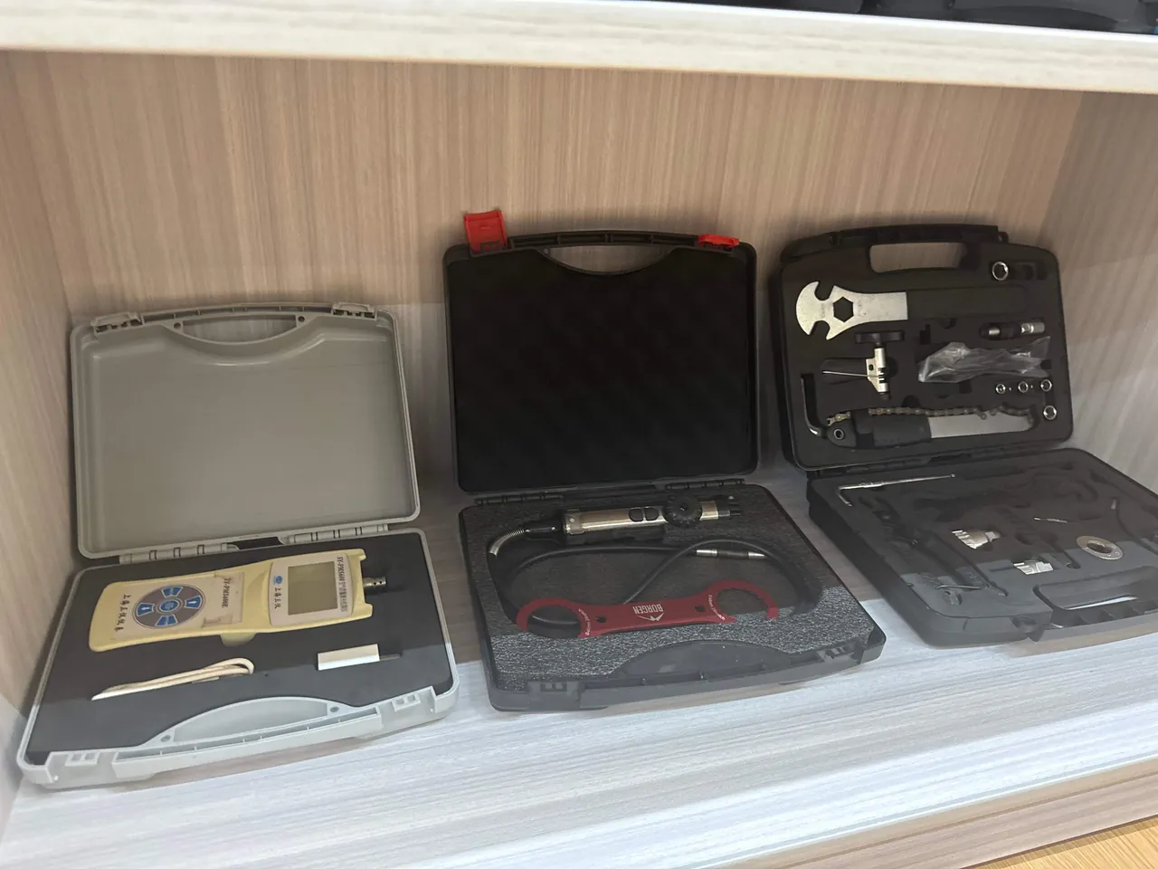
General cleaning and care methods are in how to clean a protective case, and the logic for judging when a case has reached the end of its service life appears in protective case service life. One trigger condition deserves emphasis: re-verification must be mandatory, not optional, when any one of four events occurs - the case is dropped, the shell shows visible deformation, the humidity indicator exceeds its limit, or a new scratch appears on an instrument.
13. Customization workflow and OEM/ODM collaboration
A metrology case is a made-to-list product, and standard cases almost never match a block set directly. A repeatable workflow is:
- Compile the list. Record model, size, quantity, unit weight and external dimensions for every instrument. For block sets, provide the piece count and step ranges; for ring and plug gauges, provide outer diameter, bore and height.
- Produce a compartment layout. Lay out on the principle of heavy items low, light items high, blocks separate, accessories isolated, and mark every cavity number and nominal size.
- Confirm the insert and structure. Fix insert material and hardness, cavity clearance, anti-rust paper type, and whether a swappable module plate is used. Also fix shell material, sealing class, and whether reinforced handles and lifting apertures are needed.
- Prototype and trial fit. Trial-fit the first article with the actual instruments. Check ease of handling, freedom from rattle, and absence of interference when the lid closes.
- Validate and produce. Move to serial production after drop and vibration validation, with AQL sampling as agreed.
JUNZHIJIA, manufactured by Kexin New Materials (Guangdong) Co., Ltd., supplies metrology cases with multi-cell inserts lofted from the customer's instrument list, swappable module base plates, and lid structures that integrate a desiccant bay and a document pouch. OEM/ODM support covers dimensions, color, silk-screen printing and numbering. For buyers who need acceptance evidence, cavity dimensional records keyed to the instrument list, insert material declarations, and rust or moisture verification reports can be supplied on request. Supplier evaluation and process choice are discussed in how to choose a case OEM factory and custom case acceptance and AQL.
14. Acceptance checklist and common misconceptions
Check each item at first-article and volume delivery:
- Is the clearance between each cavity and its instrument within 0.3 to 0.8 mm?
- Is there a rib taller than 60 percent of block thickness between adjacent blocks?
- Do insert hardness and density match the sample, verified by durometer spot check?
- Are nominal sizes marked beside block cavities and asset numbers beside instrument cavities?
- Are ring gauges stored upright with the outer cylinder carrying the load?
- Does the micrometer cavity guarantee the two measuring faces contact nothing after the spindle is retracted?
- Does the lid interior provide a desiccant bay, a humidity indicator position and a waterproof document pouch?
- Is the gasket continuous with no breaks, and is there no visible gap after closing?
- Is handle and lifting structure deflection acceptable under full load?
- Are material records, dimensional records and test reports complete?
Five misconceptions recur. First, wrapping items in cloth or air pillows and stacking them together. It feels soft but does nothing to stop relative motion between blocks. Second, assuming ceramic blocks need no protection at all. Ceramic does not rust but it chips, and corner impact remains fatal. Third, treating oiling and transport as one activity. The oiled state before packing and the degreasing step after arrival must be managed separately. Fourth, ignoring magnetic fields. Sitting next to a magnetic base or loudspeaker in transit magnetizes steel blocks. Fifth, accepting on appearance alone. A clean exterior does not prove the measuring faces are intact; wringing tests and flatness checks may be necessary.
Frequently Asked Questions
Q: If steel gauge blocks are coated with anti-rust oil, can they still corrode?
A: Yes, because oil works as a barrier and its effectiveness depends on film continuity, coverage of edges and apertures, and whether internal relative humidity stays below 45 percent over time. Three failure patterns are common. The first is uneven application: edges and chamfers carry the thinnest film but are the first places to rust, and once an edge rusts it raises the local height. The second is elevated humidity inside the case, where condensation beneath the film still forms an electrolyte layer, especially during transport with repeated day and night temperature swings. The third is residual hand sweat or water-based cutting fluid left on the surface, sealed under the oil film, which actually accelerates localized corrosion. The recommended sequence is therefore clean and dry thoroughly, apply a thin even film, pack with desiccant and a humidity indicator card, then on arrival wipe the film off, let temperature equalize and only then place the block on the calibration bench.
Q: Why can a gauge block not be calibrated immediately after transport?
A: The core reason is that its temperature has not equilibrated with the calibration environment, and block length is highly temperature sensitive. Steel expands at roughly 11.5 x 10⁻⁶ per kelvin, so a 100 mm steel block changes length by about 1.15 microns per degree Celsius, the same order as a grade 1 tolerance and enough to change the calibration outcome. When an instrument moves from a cold vehicle into a temperature-controlled room, the surface warms first while the core lags, so an internal gradient persists and releases slowly even after the surface feels close to ambient. Soak time depends on block size, whether blocks are stacked, and the case material and insert thickness. A working rule is at least two hours for small blocks, four hours or more for large or case-packed sets, and longer for precision work, with blocks spread out individually rather than left wrung together. Related environmental control thinking is in environmental chamber component protection.
Q: Can vapor phase corrosion inhibitor film or anti-rust paper be used inside a gauge block case?
A: Yes, but compatibility must be confirmed and it should not simply replace oil. Vapor phase inhibitors release corrosion inhibitor molecules slowly and build a protective atmosphere inside an enclosed volume, which supplements coverage at edges and apertures where oil films are thin. Three preconditions apply. First, the material must be compatible with steel blocks and also with the insert and gasket, so that the inhibitor does not age the foam or swell the seal. Second, confirm the inhibitor does not leave a residual film on measuring faces that affects wringing or size; verify with a wringing test where necessary. Third, vapor phase protection depends on an enclosed volume, so if the case sealing class is low or the case is opened frequently, inhibitor concentration cannot be maintained and actual protection drops noticeably. The practical recommendation is to use it for high-humidity or cross-climate shipments, and to rely on oil plus desiccant for routine indoor transfers.
Q: Can ceramic and steel gauge blocks share the same case?
A: Yes, but they must be in separate cavities and must never touch. Ceramic blocks need no rust protection, are hard and wear well, but they are notably brittle and their corners chip under concentrated impact. Steel blocks are tough and resist chipping but scratch and dent when they contact a harder surface. If the two sit adjacent, the ceramic corner acts like a cutting tool on the steel measuring face under transport vibration, a classic hard-damages-soft situation. The correct approach is to divide cavities by material, place ribs between them with a height exceeding 60 percent of block thickness, and allow a larger cushioning clearance for ceramic cavities, typically 0.6 to 1.0 mm. Because ceramic is less dense than steel, place steel blocks in the lower layer near the handle and ceramic blocks above, which lowers the center of gravity and reduces eccentric loading. Mark each cavity by material as well as size, since mixing the two families is the most frequent packing error in a shared case.
Q: What is the correct way to pack a micrometer, and why is it so often done wrong?
A: The correct posture can be summarized as spindle retracted, measuring faces unloaded, frame supported. The accuracy-critical features are the anvil and spindle measuring faces, which must maintain strict parallelism, and any sustained external force travels through the elastic deflection of the frame into those two faces. The most common error is dropping the micrometer in vertically so the anvil presses against the case wall or a hard insert wall, transmitting vibration straight into the measuring faces and gradually degrading parallelism. The second common error is leaving the spindle extended, so it stays in contact with the anvil and develops fretting wear in transit. The third is letting the whole micrometer weight be carried by elastic deflection of the insert, which matters little for small sizes but is unacceptable above 500 mm where the frame itself is heavy and demands a rigid support cradle. After packing, do a lid-closing trial to confirm nothing touches the measuring faces.
Q: Why must ring gauges be stored upright?
A: Because the dominant failure mode for a ring gauge is bore deformation. The critical dimensions are the internal cylinder diameter and cylindricity. If a ring gauge lies horizontally with its end face or bore wall carrying weight, the steel deforms elastically under gravity and vibration loading, and repeated cycles can leave residual deformation. Stored upright with a vertical axis, load passes through the outer cylinder into the insert cradle, and the bore carries only its own uniform hoop stress with no local contact stress, which minimizes deformation risk. Three implementation details matter: the cradle should be as wide as the gauge to avoid line contact; it should have enough height, covering at least one third of the outer cylinder, to prevent tipping; and rigid dividers rather than foam alone should separate multiple gauges, because foam loses recovery after repeated compression and once dividers fail the gauges strike each other. Thin-walled or large-bore ring gauges require strict compliance.
Q: Does a metrology case need to be rated IP67?
A: It depends on transport and storage conditions, and higher is not automatically better. IP54 resists dust and water splashing from any direction, which covers routine indoor transfer, urban delivery and sheltered loading, while consuming desiccant more slowly. IP67 tolerates short-term immersion and suits open-air loading in the rainy season, cold-chain transfer, shipboard and island projects, and long-term coastal storage. Two practical factors should also be weighed. The first is opening frequency: a higher sealing class takes longer to re-establish a dry interior after each opening, so a frequently opened high-rated case actually needs a shorter desiccant interval. The second is pressure differential, because a well-sealed case develops a significant differential after air freight or altitude crossing, making it hard to open and potentially lifting the gasket, which calls for a pressure equalization valve. The general recommendation is IP54 with disciplined desiccant management for routine use, and IP67 plus a pressure equalization valve for harsh routes.
Q: If a case is dropped in transit but the instruments look fine, is re-verification still needed?
A: Yes, and this is the step most often skipped and most likely to cause later dispute. Accuracy loss in measuring instruments usually does not appear as visible damage. A drop can produce small elastic after-effects in a micrometer frame, shift the meshing position in a dial indicator gear train, or introduce local stress in a gauge block that affects long-term dimensional stability, while the exterior shows nothing unusual. Manage this by triggering on the event rather than on the conclusion: if the case is dropped, the shell shows visible deformation, the humidity indicator exceeds its limit, or a new scratch appears on an instrument, send it for verification rather than deciding after a visual check. To make that workable, keep a shock or vibration recording label in a fixed position inside the case and record the date and route of every transfer on a history card, so responsibility and traceability have a factual basis.
Q: How can an on-site calibration provider cover many tasks with a single case?
A: The mainstream approach is a swappable module base plate plus multiple module sets. The base plate is a standard grid fixed in the case, and the block module, instrument module and ring or plug gauge module are lofted to their own dimensions, with locating and anti-lift features so each module sits flush when inserted. Before departure, select modules against the day's task list, which cuts packing time from tens of minutes to a few minutes. Four constraints apply. Different modules change the loaded center of gravity, so insert heavy modules centrally and near the handle. Anti-lift features are essential, because a lifted module loses its locating function. Each module set needs an identifier and the case needs a configuration list, otherwise mismatching is inevitable over time. And because modules share one base plate, cavity accuracy is limited by the plate grid tolerance, so precision sets such as grade 0 blocks are better served by a fully form-fit insert. See removable divider system design.
Conclusion and Further Reading
Five things decide whether a metrology case works: one cavity per item, a low-humidity interior, thermal buffering with a soak discipline, magnetic isolation, and traceable in-case records. Achieve all five and accuracy loss in transit stays negligible.
Further Reading