

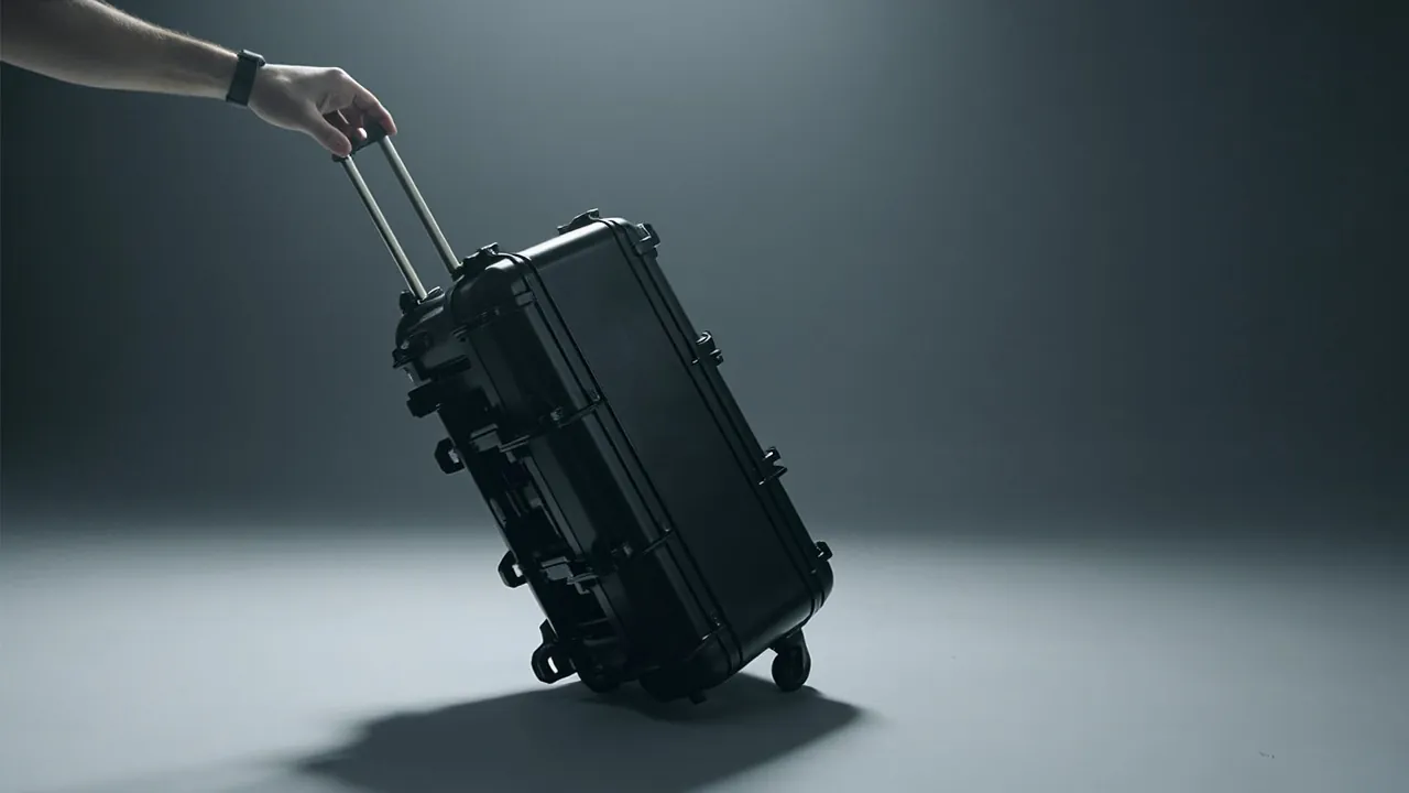
Short answer: a protective case can certainly be fitted with wheels, but "it can be fitted" does not mean "it works well" — three gates must be passed: load matching, interface strength and centre-of-gravity stability. Load matching means the castor's single-wheel rated load must carry enough safety margin to absorb dynamic impact and uneven ground. Interface strength means the case body where the wheel set is mounted must have reinforcing structure, or it will tear under heavy load. Stability means the trolley handle angle and case height must match, or a full load will tip backwards or be exhausting to push. The most common error is not choosing wheels that are too small, but choosing them from static weight alone while ignoring the dynamic factor and ground conditions. A case at a 40 kg static gross weight can subject its wheels to instantaneous loads several times higher while being pushed. The correct method has four steps: calculate gross weight and per-wheel distribution, set the wheel diameter from ground conditions, set the wheel-set specification from the dynamic factor, and finally verify interface strength and centre of gravity. This article gives a wheel-type comparison, a load verification table, trolley handle design points, treatment of interface and sealing effects, and an executable selection and verification checklist. All figures are typical or empirical values; the castor supplier's load data and actual testing govern, and castor testing can follow the EN 12527 series methods.
Many buyers ask one question when adding a mobility requirement — "can you fit wheels?" — and end the conversation once told "yes". What actually needs confirming is not whether wheels can be fitted but what specification, whether the case body needs a structural change, and whether the ingress protection rating is affected. If these three are not settled during prototyping, production often pays for a tool change or a downgraded configuration. Fitting a wheel set changes four things at once: how the case carries load (from distributed static pressure to local point loading), the centre of gravity (the handle moves it outwards), the sealing path (mounting may pass through the wall), and the user experience (wheel diameter matched to ground decides how easily it rolls). This article is written for sourcing and engineering staff at brand owners, trading companies and equipment makers who need a mobility solution for heavy equipment, tools and apparatus.
Table of Contents
- Start with the conclusion: wheels are possible, but three gates must pass
- When wheels are worth adding: weight and frequency criteria
- Castor types: fixed, swivel and braked
- Wheel diameter and clearance: ground conditions set the diameter
- Load matching: per-wheel load, dynamic factor and safety margin
- Trolley handle structure: stages, tube, grip and play
- The case-to-wheel interface: reinforced zones and mounting plates
- Centre of gravity and stability: handle angle and tipping risk
- How sealing and protection interact
- Common failure modes and prevention
- Selection and verification checklist
- FAQ
- Closing remarks and related reading
Start with the conclusion: wheels are possible, but three gates must pass
Break the conclusion into executable judgements.
Gate one: load matching. Calculate how the gross weight distributes across the wheels, then add the dynamic factor and safety margin to arrive at the required single-wheel rated load. Passing statically does not mean passing dynamically — pushing, crossing kerbs and dropping off steps all produce instantaneous loads far above static.
Gate two: interface strength. A wheel set concentrates load onto a few points of the case body. Those points must be supported by reinforced zones, mounting plates or metal inserts, or they will crack from the mounting holes under heavy load or sustained vibration.
Gate three: stability. With the handle extended, the position of the case-plus-load centre of gravity relative to the ground changes; a poorly chosen angle makes pushing exhausting, loads the wheels abnormally, or tips the case backwards when stationary.
| Gate | Question to answer | Consequence of failure |
|---|---|---|
| --- | --- | --- |
| Load matching | Does single-wheel rated load cover the dynamic load? | Wheel deformation, bearing damage, binding |
| Interface strength | Does the mounting zone have reinforcement? | Case wall cracking, wheel set detaching |
| Stability | Do handle angle and case height match? | Tipping, exhausting to push |
This is the same class of question as choosing a wheeled case at all. For the trade-off between wheeled and ordinary toolboxes see wheeled versus normal toolboxes; for industry applications of trolley cases see trolley toolbox industries.
When wheels are worth adding: weight and frequency criteria
A wheel set is not "better the earlier it is added" but "worthwhile once the threshold is reached".
Two criteria:
- Weight criterion. If the gross weight exceeds the comfortable single-person carrying limit (an industry empirical range of 20 to 25 kg), manual handling efficiency and safety fall noticeably. There are then three paths: reduce the load, fit a wheel set, or move to palletised transfer. Note: occasional short-distance carrying can stretch to around 30 kg, but should not become the norm.
- Frequency criterion. If a single carrying distance is long, or daily handling frequency is high, the efficiency gain from wheels quickly exceeds their weight and volume cost.
Conversely, wheels are not recommended in these situations:
- Gross weight far below 20 kg, where wheels only add tare weight and cost;
- Mainly used on gravel, crushed stone or mud, where a small wheel can barely roll and a large wheel adds significant weight;
- Frequent stairs or step crossings, where wheels help little but add weight;
- Warehousing dominated by forklift or pallet handling, where wheels add little value.
A practical reminder: judge "wheels" and "trolley handle" separately. Some situations suit wheels but not a handle (for example a low case used mainly for short-distance shifting); others need both together (for example a tall case moved between offices or stations).
Castor types: fixed, swivel and braked
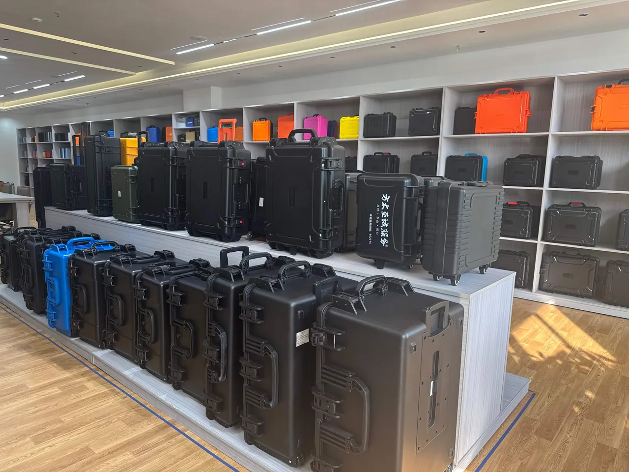
The castor type decides rolling experience and stability.
| Type | Characteristic | Advantage | Limit |
|---|---|---|---|
| --- | --- | --- | --- |
| Fixed | Travels straight only | Straight-line stability, simple, high load | Must be lifted to turn |
| Swivel | Turns through 360 degrees | Flexible steering, good in tight spaces | Wanders when pushed straight, ground-sensitive |
| Braked | Has a brake or lock | Holds position, prevents rolling away | Adds cost and a step |
| Combination (fixed plus swivel) | Swivel front, fixed rear | Balances stability and steering | Needs front-rear balance |
An empirical approach to combination: if the case has only two wheels (used with the handle tilted), fixed wheels are usual; if it has four wheels (pushed upright), the common combination is two swivel plus two fixed, or four swivel with brakes. Four swivel wheels wander when pushed in a straight line, forcing the user to keep correcting direction, which is more tiring over distance.
A reminder: wheel count must match case size. Too few wheels overloads each; too many makes the case rock on uneven ground, with only one wheel carrying load. For related base structure and stacking, see case stacking structure design.
Wheel diameter and clearance: ground conditions set the diameter
Wheel diameter is the first variable deciding whether a case can be moved at all, more than material or bearings.
| Ground condition | Diameter tendency | Reason |
|---|---|---|
| --- | --- | --- |
| Flat indoor (epoxy, tile) | Small to medium | Low resistance, smaller wheels lighter |
| Factory concrete/asphalt | Medium | Must cross gaps and small obstacles |
| Outdoor gravel, grass | Medium to large | Small wheels sink, resistance high |
| Thresholds, grates, cable ducts | Large | Needs enough obstacle clearance |
| Stairs (no ramp) | Wheels not advised | Wheels cannot replace carrying |
Key concept: obstacle clearance scales with wheel diameter. The height a wheel can climb is roughly proportional to its diameter, so a small wheel jams at a threshold or cable duct and has to be lifted by hand. So the rule is: the worse the ground, the larger the wheel.
Also consider wheel width and material. Hard wheels (nylon, polyurethane) roll easily and wear well on hard ground but transmit vibration and noise; soft wheels (rubber, TPE) damp vibration and run quietly but have higher rolling resistance and slightly lower load capacity. The softer the ground, the wider the wheel should be, to lower contact pressure and avoid sinking.
Load matching: per-wheel load, dynamic factor and safety margin
This is the most easily simplified and most failure-prone part.
Step one: calculate the per-wheel distributed load.
Per-wheel load = gross weight x distribution factor
Note that the distribution factor is not simply one divided by the number of wheels. On uneven ground the weight tends to concentrate on a few wheels; a conservative approach distributes over "wheel count minus one" or the worst-case combination. For a four-wheel case, calculate on two or three wheels carrying, not four sharing equally.
Step two: add the dynamic factor. Pushing, crossing kerbs, dropping off steps and sudden stops all create dynamic load. Dynamic load is typically several times static load, and the multiple depends on speed, obstacle height and ground stiffness. This is the root of "passes statically, fails dynamically".
Step three: leave a safety margin. Multiply the dynamic load by a safety factor to obtain the required single-wheel rated load.
| Verification item | Description | Approach to value |
|---|---|---|
| --- | --- | --- |
| Gross weight | Case tare plus contents plus insert | Sum the actual list |
| Distribution factor | Per-wheel share | Worst case (wheel count minus one) |
| Static per-wheel load | Gross weight x distribution factor | Calculated |
| Dynamic factor | Impact amplification | Empirical value from speed and ground |
| Safety margin | Long-term reliability reserve | Further factor on dynamic load |
| Single-wheel rated load | Supplier data | Must be at or above the verified value |
A hard criterion: use the supplier's rated load, and note that the rating normally corresponds to specific speed and ground conditions. If actual speed, ground or temperature is outside the supplier's conditions, derate further. Do not judge compliance by "the peak load held up temporarily" — castor failure is usually progressive (bearing wear, wheel deformation) and occurs suddenly at a critical point.
Trolley handle structure: stages, tube, grip and play
The handle decides how easy the case is to pull.
Number of stages. A single-stage handle is simple with little play; a two- or multi-stage handle extends further and stows more compactly but has more interfaces and more play. The more stages, the more attention the locking mechanism reliability and clearance control need.
Tube. Steel and aluminium are common. Steel is strong and stiff but heavy; aluminium is light but wall thickness and joint strength need attention. Diameter and wall thickness together set bending strength — a handle carries a bending moment when pulling a full load, and the longer it is, the larger the diameter or thicker the wall must be.
Grip. Consider comfort, anti-slip texture and space — if used with gloves, the grip diameter and shape need allowance.
Play. Handle play is a common complaint. It comes from clearance between stages and the fit of the locking mechanism. The design should define the fit tolerance for each stage, and acceptance should use "lateral play when pulling a full load" as the criterion.
| Handle parameter | Effect | Focus |
|---|---|---|
| --- | --- | --- |
| Number of stages | Stowed length and play | Locking reliability |
| Tube and wall thickness | Bending strength and weight | Deflection under full load |
| Grip | Comfort and anti-slip | Usability with gloves |
| Fit clearance | Degree of play | Lateral play under full load |
A reminder: handle load capacity is not "can it pull" but "is it still stable at full load, on poor ground, after long use". For related drawing call-outs see the technical parameter checklist for protective case drawings.
The case-to-wheel interface: reinforced zones and mounting plates
The case body ultimately carries the wheel and handle loads, so the interface is a key structural design point.
Three interface treatments:
- Local reinforced zones. Thicken the wall or add ribs at the mounting location to spread the point load over a larger area. See case reinforcement rib design.
- A separate mounting plate. Embed or externally fit a rigid mounting plate to the case, fix the wheel set to the plate, and let the plate spread the load across its face.
- Metal inserts. Mould metal inserts into the part as threaded load points, avoiding tapping directly into plastic, which strips under repeated assembly or vibration.
Key criterion: load must be converted from a point to a face. Fixing a wheel set to a thin wall with self-tapping screws cracks easily at the hole under heavy load or vibration. The approach is: wheel set → mounting plate/reinforced zone → case main structure, forming a graduated load path.
For overall case structural strength, see high-strength case structure and protective case plastic materials.
Centre of gravity and stability: handle angle and tipping risk
Centre of gravity decides pushing effort and static safety.
Three relationships:
- The taller the case and the shorter the handle, the higher the centre of gravity relative to the wheel axle and the greater the tipping risk.
- Too small a handle angle (near vertical) forces the user to press down hard to keep balance, making pushing exhausting.
- Too large an angle (excessive lean-back) moves the case centre of gravity outwards too far and tends to tip backwards.
An empirical approach is to set a handle angle in the working position that gives the case weight a forward component about the wheel axle, helping balance. Also verify stability in the static upright position — a full load with the handle stowed should not tip because the centre of gravity sits too far back.
The same principle applies to loading: put heavy items low and near the wheel axle, avoiding heavy items on top that raise the overall centre of gravity. See the centre-of-gravity discussion in wheeled versus normal toolboxes.
How sealing and protection interact

Will fitting wheels and a handle break the ingress protection rating? It depends on whether the mounting creates a through-wall path.
- External mounting: the wheel set and handle bracket fix to the case exterior without penetrating the cavity, normally without affecting the rating.
- Through-wall mounting: bolts pass through the wall into the cavity, and each hole is a potential leak path that must be sealed individually — gaskets, sealant or sealed fasteners.
- Shared hinge or latch positions: if the wheel bracket uses the hinge or latch mounting points, the seal compression may change and must be re-verified.
A hard reminder: any through-wall mounting should be re-verified for ingress protection. The rating follows IEC 60529 and GB/T 4208 criteria, and a sample that passes IPX7 does not necessarily pass the IPX5 jet test, because the two assess different failure modes (static water pressure versus dynamic water impact), so the technical agreement must state each digit. For criteria detail see understanding the IP67 rating; for seal and compression matching see case seal materials.
Common failure modes and prevention
List the most common failures so design can avoid them early.
| Failure mode | Root cause | Prevention |
|---|---|---|
| --- | --- | --- |
| Wheel flattened or deformed | Per-wheel load exceeds dynamic load | Raise rated load or add wheels |
| Bearing noise or binding | Dust, lack of lubrication, overload | Sealed bearings, scheduled maintenance |
| Mounting hole cracking | Point load directly on thin wall | Reinforced zone, mounting plate, metal insert |
| Handle bending | Insufficient tube diameter or wall thickness | Increase diameter or wall thickness |
| Handle play | Excessive clearance between stages | Control fit tolerance |
| Static tipping | Centre of gravity too far back, handle extended | Verify static stability |
| Seal leakage | Unsealed through-wall holes | Seal each hole and re-test protection |
| Swivel wandering | Four swivel wheels pushed straight | Use swivel front plus fixed rear |
How to use it: run these eight items as a design review checklist. Confirm each in every review, especially "mounting hole cracking" and "seal leakage" — their symptoms usually appear only after long use, when rework is most costly.
Selection and verification checklist
The content above collapses into an executable checklist.
At selection:
- Calculate gross weight (case tare, contents and insert) and the worst-case per-wheel load.
- Set the wheel diameter tendency, width and material from ground conditions.
- Decide the castor type combination (fixed, swivel, braked).
- Set the required single-wheel rated load from the dynamic factor and safety margin.
- Define handle stages, tube diameter, grip and fit clearance requirements.
- Design the interface reinforcement (reinforced zone, mounting plate, metal insert).
- Verify stability in the working handle position and in the static upright position.
- Confirm whether mounting passes through the wall and plan the sealing method.
At verification:
| Verification item | Method | Criterion |
|---|---|---|
| --- | --- | --- |
| Full-load rolling | Push a full load over the actual route | No significant wandering, binding or noise |
| Obstacle crossing | Cross an actual threshold or duct | Crosses, or needs a controllable lift |
| Handle stiffness | Observe deflection while pulling a full load | Deflection within acceptable range |
| Handle play | Measure lateral play while pulling a full load | Within the agreed limit |
| Interface strength | Inspect holes after loading or vibration | No cracking, no loosening |
| Ingress protection | IEC 60529 / GB/T 4208 | Meets the agreed conditions |
| Long-term reliability | Test design along ISTA / ASTM D4169 lines | No progressive damage |
Three recommendations for use: first, quantify before selecting — calculate gross weight and per-wheel load before deciding diameter, type and specification, rather than picking wheels first and working backwards; second, design the interface and the seal together, since through-wall mounting means re-running the protection verification to the agreed conditions of IEC 60529 and GB/T 4208; third, put verification into the prototyping checklist, since full-load rolling, obstacle crossing and interface inspection cost little yet reveal most problems early.
JUNZHJIA, manufactured by KeXin New Materials (Guangdong) Co., Ltd., covers protective cases, toolboxes, military-specification storage boxes and waterproof junction boxes, serving wholesale, distribution, OEM/ODM and global supply. It can configure castor and trolley handle solutions to customer load and ground conditions, provide interface reinforcement design, structural verification and ingress protection verification support, and issue inspection documents.
FAQ
Q: Can a protective case be fitted with wheels, and does it affect the ingress protection rating? A: It can, and whether the rating is affected depends on the mounting method. External mounting, where the wheel set and handle bracket fix to the case exterior without penetrating the cavity, normally does not affect the rating. Through-wall mounting, where bolts pass through the wall into the cavity, creates a potential leak path at every hole that must be sealed individually, with gaskets, sealant or sealed fasteners. In addition, if the wheel bracket uses the hinge or latch mounting points, the seal compression may change and must be re-verified. A hard reminder: any through-wall mounting should be re-verified for ingress protection. The rating follows IEC 60529 and GB/T 4208 criteria, and note that water protection levels are not a simple progression — a sample that passes IPX7 does not necessarily pass the IPX5 jet test, because the two assess different failure modes (static water pressure versus dynamic water impact), so the technical agreement must state the test conditions digit by digit. If the solution involves through-wall mounting, put the protection test into the prototyping verification checklist to avoid rework at production.
Q: How should castor load capacity be chosen? Is static weight enough? A: No — judging on static weight alone is the most common error. Verification has three steps. Step one: calculate the per-wheel distributed load, noting the distribution factor is not one divided by the number of wheels — on uneven ground weight concentrates on a few wheels, so a conservative approach distributes over "wheel count minus one" or the worst-case combination. Step two: add the dynamic factor; pushing, crossing kerbs, dropping off steps and sudden stops all create dynamic load, typically several times the static load, with the multiple depending on speed, obstacle height and ground stiffness. Step three: leave a safety margin, multiplying the dynamic load by a safety factor to obtain the required single-wheel rated load. The criterion is the supplier's rated load, and that rating normally corresponds to specific speed and ground conditions; if actual speed, ground or temperature is outside those, derate further. Do not judge compliance by "the peak load held up temporarily" — castor failure is usually progressive (bearing wear, wheel deformation) and occurs suddenly at a critical point. Correspondingly, an excessive single-wheel load is one of the most common root causes of failure.
Q: What wheel diameter should be chosen? A: It follows from ground conditions, and the worse the ground, the larger the diameter. The core concept is that obstacle clearance scales with diameter: the height a wheel can climb is roughly proportional to its diameter, so a small wheel jams at a threshold or cable duct and has to be lifted by hand. A rough mapping: flat indoor ground (epoxy, tile) suits a small to medium diameter, with low resistance and lighter weight; factory concrete or asphalt suits a medium diameter to cross gaps and small obstacles; outdoor gravel and grass suit a medium to large diameter because small wheels sink and resistance is high; thresholds, grates and cable ducts need a large diameter for obstacle clearance; pure stairs without a ramp are not suited to wheels, which cannot replace carrying. Also consider wheel width and material: the softer the ground, the wider the wheel should be, to lower contact pressure and avoid sinking. On material, hard wheels (nylon, polyurethane) roll easily and wear well on hard ground but transmit vibration and noise, while soft wheels (rubber, TPE) damp vibration and run quietly but have higher rolling resistance and slightly lower load capacity. Confirm the ground and speed conditions the supplier's rating refers to.
Q: The handle has a lot of play and the case is exhausting to push — what is wrong? A: Usually one of three causes. First, excessive clearance between handle stages. Play comes from clearance between stages and the fit of the locking mechanism; more stages mean more interfaces and more play. The design should define the fit tolerance for each stage, and acceptance should use "lateral play when pulling a full load" rather than feel. Second, an incorrect angle. Too small an angle (near vertical) forces the user to press down hard to keep balance, making pushing exhausting; too large an angle (excessive lean-back) moves the centre of gravity outwards too far and tends to tip backwards. An empirical approach is to set a handle angle in the working position that gives the case weight a forward component about the wheel axle to help balance. Third, insufficient tube diameter or wall thickness. A handle carries a bending moment when pulling a full load, and the longer it is, the larger the diameter or thicker the wall must be; steel is strong and stiff but heavy, aluminium is light but needs attention to wall thickness and joint strength. Also judge "wheels" and "handle" separately — some situations suit wheels but not a handle (for example a low case used mainly for short-distance shifting), and not every wheeled case needs a handle.
Q: Why do wheel-set interfaces crack on heavy cases, and how can it be avoided? A: The root cause is a point load acting directly on a thin wall without being spread into a face load. Fixing a wheel set to a thin wall with self-tapping screws cracks easily at the hole under heavy load or vibration; and tapping directly into plastic rather than using a metal insert strips under repeated assembly or vibration. There are three levels of correct treatment: a local reinforced zone, thickening the wall or adding ribs at the mounting location to spread the point load over a larger area; a separate mounting plate, embedded or externally fitted as a rigid plate to which the wheel set is fixed, spreading load across the plate face; and metal inserts, moulded in as threaded load points. The key criterion is a graduated load path: wheel set → mounting plate/reinforced zone → case main structure. The verification method is to inspect the holes after a loading or vibration test, with the criterion of no cracking and no loosening. Put "mounting hole cracking" and "seal leakage" among the priority design review items, because their symptoms usually appear only after long use, when rework is most costly.
Q: How do I choose between a wheeled case and an ordinary toolbox? A: It depends on weight, frequency and ground. Criterion one, weight: if the gross weight exceeds the comfortable single-person carrying limit (an industry empirical range of 20 to 25 kg, stretchable to around 30 kg for occasional short-distance carrying), manual handling efficiency and safety fall noticeably, and wheels or palletised transfer should be considered. Criterion two, frequency: if a single carrying distance is long or daily handling frequency is high, the efficiency gain from wheels quickly exceeds their weight and volume cost. Criterion three, ground: performance differs greatly on uneven ground, and wheel diameter must match it. Situations where wheels are not recommended include: gross weight far below 20 kg (adding only tare weight and cost); mainly gravel or mud use (small wheels cannot roll, large wheels add significant weight); frequent stairs or step crossings (wheels help little); and warehousing dominated by forklift or pallet handling (wheels add little value). Also judge "wheels" and "handle" separately. Before deciding, compare the structural differences between wheeled and ordinary toolboxes and whether they affect stacking and protection.
Q: Are four swivel castors better than fixed wheels? A: Not necessarily — it depends on how the case is used. Swivel castors steer flexibly and are good in tight spaces, but wander when pushed straight and are ground-sensitive — four swivel wheels force the user to keep correcting direction, which is more tiring over distance. Fixed wheels travel straight, are simple and carry high loads, but must be lifted to turn. The usual combination is therefore swivel front plus fixed rear, balancing straight-line stability with steering flexibility; if the case has only two wheels (used with the handle tilted), fixed wheels are usual. Where the case must hold position or not roll away, braked castors can be added at the cost of extra cost and a step. Another criterion is that wheel count must match case size: too few wheels overloads each, too many makes the case rock on uneven ground with only one wheel carrying load, so a four-wheel case should be verified on the worst-case two or three wheels rather than four sharing equally. The final choice should combine ground conditions, pushing distance, need to hold position and budget.
Q: How do I verify reliability after fitting a wheel set? A: Verify six items, ideally during prototyping. First, full-load rolling: push over the actual route, with the criterion of no significant wandering, binding or abnormal noise. Second, obstacle crossing: cross an actual threshold or cable duct, with the criterion that it crosses or needs a controllable lift. Third, handle stiffness: observe deflection while pulling a full load and check it is within an acceptable range. Fourth, handle play: measure lateral play while pulling a full load against the agreed limit. Fifth, interface strength: inspect the holes after loading or vibration, with the criterion of no cracking and no loosening. Sixth, ingress protection (where through-wall mounting is involved): re-test to the agreed conditions of IEC 60529 and GB/T 4208. Long-term reliability tests can be designed along the lines of the ISTA series or ASTM D4169. The three cheapest — full-load rolling, obstacle crossing and interface inspection — reveal most problems early. Record the results in the prototyping deliverables checklist and fix key parameters such as single-wheel rated load, dynamic factor and safety margin in the drawing and technical requirements for later production comparison.
Closing remarks and related reading
Back to the title question: a protective case can certainly be fitted with wheels, but "it can be fitted" does not mean "it works well" — it must pass three gates: load matching, interface strength and stability. Load matching means not judging on static weight alone but distributing over the worst-case single wheel, adding the dynamic factor and leaving a safety margin to obtain the required single-wheel rated load. Interface strength means converting a point load into a face load through reinforced zones, mounting plates and metal inserts to form a graduated load path. Stability means matching handle angle to case height and verifying that the case does not tip in the static upright position. Beyond that, wheels and handle should be judged separately, wheel diameter follows ground conditions, and any through-wall mounting requires re-verification of the ingress protection rating.
Three actionable recommendations. First, quantify before selecting — calculate gross weight and per-wheel load before deciding diameter, type and specification, rather than picking wheels first and working backwards. Second, design the interface and the seal together, since through-wall mounting means re-running the protection verification to the agreed conditions of IEC 60529 and GB/T 4208. Third, put verification into the prototyping checklist, since full-load rolling, obstacle crossing and interface inspection cost little yet reveal most problems early.
JUNZHJIA, manufactured by KeXin New Materials (Guangdong) Co., Ltd., covers protective cases, toolboxes, military-specification storage boxes and waterproof junction boxes, serving wholesale, distribution, OEM/ODM and global supply, and can configure castor and trolley handle solutions to customer load and ground conditions with interface reinforcement design, structural verification and ingress protection verification support.
Related reading