

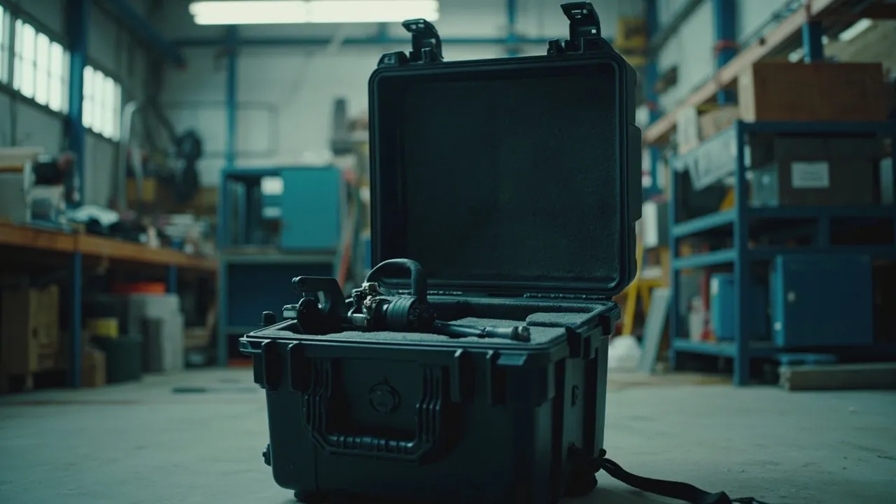
The fixtures and the load cell of a materials testing machine are the two component groups that determine whether the test data can be trusted, and they are also the two groups most easily damaged in ways you cannot see. If a fixture grip face is scored or its alignment shifts, the stress state imposed on the specimen changes. If the load cell zero drifts, the force indication of the entire machine loses its basis. The conclusion is unambiguous: these two categories must travel in a purpose-built case with custom foam, controlled sealing and positive restraint, and they must never share a case with frames or sheet metal parts.
Materials testing machines, including universal testing machines, hydraulic universal machines, tensile testers, compression testers and fatigue machines, are normally partially disassembled for factory dispatch, laboratory relocation, return for verification or calibration, and inter-plant transfers. The reason is practical. The frame itself is a heavy casting or steel weldment with good resistance to impact, whereas fixtures and sensors are the exact opposite: high unit cost, defined accuracy class, and a mandatory re-verification after any failure. If a machine that has already passed its intermediate check arrives with a force indication out of tolerance, the time consumed by a return to verification far exceeds the cost of a compliant protective case.
This article is written for the dispatch and after-sales teams of testing machine manufacturers, the equipment management staff of third-party testing bodies and quality inspection centres, laboratory heads in universities and research institutes, and the engineering procurement staff who run whole-laboratory relocations. It breaks down the fragile points of each component group, the choice of sealing rating, liner design and restraint methods, rust prevention strategy for machined metal surfaces, the transport test standards that apply, and an acceptance method that can be written directly into a purchase contract.
Table of Contents
- 1. Why Materials Testing Machine Components Need a Purpose-Built Case
- 2. Testing-Machine Component List and Fragility Grading
- 3. Fixture Protection: Wedge, Tensile and Bend Fixtures
- 4. Hydraulic Grips and Grip Power Units
- 5. Preserving Load Cell Accuracy
- 6. Extensometers and Displacement Measuring Components
- 7. Servo Motors, Ball Screws and Transmission Parts
- 8. Controllers and Data Acquisition Components
- 9. Ingress Rating Tiers for Fixtures and Transducers
- 10. Load Path and Cushioning for Heavy Fixtures
- 11. Rust and Moisture Control for Ocean Freight
- 12. Load Spectra and the Validation Basis for Testing-Machine Components
- 13. Pairing Marks, Transducer Traceability and Flammability Declarations
- 14. Selecting and Releasing a Testing-Machine Component Case
- Frequently Asked Questions
- Conclusion & Related Reading
1. Why Materials Testing Machine Components Need a Purpose-Built Case
The core value of a materials testing machine is that it produces trustworthy force and deformation data. That trust rests on two preconditions. The fixture must transmit load to the specimen in the specified attitude and with the specified contact pattern. The load cell must convert that load into an electrical signal accurately. Both conditions are extremely sensitive to geometric precision.
Fixture failure is geometric failure. Once the tooth face of a wedge grip is chipped, clamping creates a stress concentration on the specimen surface and the specimen may fracture prematurely at the grip. Once the upper and lower gripping centres of a tensile fixture are no longer coaxial, the test introduces a bending moment and both yield strength and tensile strength results shift. Once the roller spacing of a bend fixture changes, the calculation basis for bending stress changes with it. Damage of this kind is measured in millimetres or micrometres, and it is very hard to detect visually at incoming inspection.
Sensor failure is metrological failure. A strain gauge load cell consists of an elastic body, strain gauges and a sealing structure. Under overload or shock the elastic body develops residual strain, which appears as a combined drift in zero and sensitivity. The bonding layer of the strain gauge can micro-crack under repeated vibration, which shows up as reading jumps or increased hysteresis. Either way, there is only one remedy: send the unit for verification and re-apply the verification or calibration label, and reassess the validity of any data the machine produced beforehand, following the usual practice for equipment competence management under ISO/IEC 17025.
A custom protective case performs three specific functions here:
- Geometric locking. Custom foam restrains the component in the specified attitude and prevents relative movement and mutual impact during transport.
- Environmental isolation. A sealed case with desiccant and rust prevention blocks moisture, salt mist and dust.
- Traceable delivery. Marking, a packing list and unboxing records let the receiver judge immediately whether the transport was abnormal.
The usual arrangement when JUNZHJIA supports the testing machine industry is that the manufacturer supplies the component list with weight and centre-of-gravity data, the brand produces the liner layout drawing and case specification, a first article is trial fitted, and then the batch is supplied. That sequence reduces the probability of a transport problem to a very low level.
2. Testing-Machine Component List and Fragility Grading
Teardown lists differ between models, but core components overlap heavily. The table below maps component category to failure mode, sensitivity and recommended protection level, and can be used directly to draft a transport packaging work instruction.
| Component group | Representative items | Dominant failure mode | Fragility tier | Packaging configuration |
|---|---|---|---|---|
| --- | --- | --- | --- | --- |
| Mechanical fixtures | Wedge grips, V-grips, tensile fixtures | Grip face chipping, loss of alignment, guide face scoring | Very high | IP67 hard case with precision liner |
| Bend and compression fixtures | Three-point bend rig, platens, support rollers | Roller spacing change, platen flatness loss | High | IP65 hard case with individual pockets |
| Hydraulic grips | Hydraulic grip heads, clamping cylinders | Port damage, seal ageing, piston rod bending | High | IP65 hard case with port plugs |
| Hydraulic power units | Hydraulic power pack, accumulators, valve blocks | Leakage, gauge damage, pipe deformation | Medium | IP65 hard case with zoned liner |
| Load cells | S-type, pancake, column load cells | Zero drift, overload damage, cable strain | Very high | Individual pocket, ESD bag, desiccant |
| Deformation measurement | Clip-on and optical extensometers | Knife edge damage, flexure beam deformation, optical misalignment | Very high | Box-in-box with vibration pads |
| Transmission | Servo motor, ball screw, timing pulley | Screw bending, encoder shock, shaft end damage | Medium-high | IP65 hard case with axial support |
| Electrical control | Controller, DAQ card, industrial PC, drive | Terminal loosening, board moisture, ESD damage | High | ESD protection plus desiccant |
| Accessories | Grip inserts, spacers, wrench sets | Tooth face chipping, loss | Medium | Zoned small pockets with a checklist |
The critical action after grading is one drawing per case. For every case, produce a liner layout drawing that records the part name, quantity, unit weight limit and removal sequence for each pocket. That drawing serves simultaneously as a production document, an unloading guide and a traceability record. For heavy fixtures it should also mark the centre of gravity and state whether strap plates are required.
Take particular care not to put fixtures and sensors in the same pocket. A fixture is hardened steel, while a sensor is a precision item with a cable. The hardness and stiffness difference is large, and under vibration they will abrade or crush each other.
3. Fixture Protection: Wedge, Tensile and Bend Fixtures
Fixtures carry the load in a testing machine and are usually made from hardened or alloy steel, so they look insensitive to knocks. The real problem is not strength but geometric precision and the condition of the contact surfaces.
Wedge grips and tensile fixtures:
- Tooth and grip faces. This is the surface that must never be damaged. The liner needs a suspended pocket that leaves the grip face touching nothing at all, rather than letting the insert block lie flat on foam.
- Guide faces and slides. The inclined faces of a wedge insert are lapped as a pair, and scoring changes the clamping force distribution. Leave clearance in the liner so the inclined faces touch nothing.
- Alignment. Upper and lower fixtures are usually used as a matched set and have been aligned. Keep the set in one case and mark the pairing number on the drawing so they cannot be mismatched on site.
- Self-weight support. A single wedge fixture often weighs 15 to 40 kg. The liner base needs a high-density EVA or PE load plate, and pocket depth should cover the height above the centre of gravity so the part cannot topple under lateral shock.
- Lifting and carrying. Fit handles or castors on very heavy fixture cases and mark the gross weight on the lid.
Bend and compression fixtures:
- Support rollers and indenters. Rollers are cylinders and tend to roll. Route arc-shaped pockets so the restraint is face contact rather than line contact.
- Spacing retention. The adjustable rollers of a three-point or four-point bend rig shift easily in transit. Fix them with locating pins or lock screws, and note "lock the position before transport" on the list.
- Platen flatness. Large platens are flat parts and will warp permanently if stacked under load. Store them vertically or singly, and never place weight on top.
One useful general rule for fixture packing is that working surfaces must not carry load, and load-bearing surfaces must not touch anything. Let the fixture carry its weight through non-working structural features while the working contact faces stay suspended, so even if a shock occurs, the damage is not on a critical geometric face.
For fixtures that are periodically checked for geometric accuracy, such as for alignment or flatness, include a fixture status card in the case recording the last check date and result, so the site can schedule the next check on time.
4. Hydraulic Grips and Grip Power Units
Hydraulic grips and hydraulic power units are components that carry oil, pressure and seals, so the protection logic differs from purely mechanical parts: mechanical damage must be prevented, and so must leakage and contamination.
Hydraulic grip heads and clamping cylinders:
- Piston rod. The plated surface is the working face for the seal, and any score causes leakage. During transport the rod must be sleeved, or fully retracted with a mechanical limit fitted.
- Ports and fittings. Plug every port to keep debris out and protect the threads. Plug specifications should match the machine so that a matching part can be found on site.
- Seals. Rubber seals are sensitive to temperature and ozone, and should not remain compressed or exposed to direct sunlight for long periods. On long transit, pack the perishable seals separately rather than leaving them compressed in the cylinder.
- Bleed and test points. Test couplings are exposed weak points and need relief pockets in the liner.
Hydraulic power packs and valve blocks:
- Reservoir. Confirm oil level and fixing method before transport. Shipping empty reduces oil surge but requires internal rust prevention; shipping with oil requires a well sealed tank and prevention of overflow through the breather.
- Accumulator. This is a pressure vessel component and must be depressurised to the manufacturer's requirement before transport. This should be a mandatory step in the transport work instruction.
- Pressure gauges. The gauge head and stem are classic breakage items. Remove and wrap them individually, or provide a dedicated vibration-isolated pocket in the case.
- Piping. Coil hoses to a generous radius to avoid kinking; support rigid pipes so that no unsupported span can fatigue under vibration.
A compliance point worth emphasising: hydraulic transport protection should take no leakage and no environmental contamination as the baseline. If oil remains inside the component, choose oil-resistant liner material and fit an absorbent pad in the case so that oil does not soak into the foam and then slowly outgas onto the component.
When JUNZHJIA supports this category, the standard approach is to separate dry parts from oil-carrying parts. Liners for oil-carrying parts use oil-resistant EVA or XPE, with a barrier film at the base of the case, which reduces follow-up maintenance.
5. Preserving Load Cell Accuracy
The load cell is the core of the metrological chain in a materials testing machine. In a typical strain gauge cell, the accuracy class is expressed as a percentage of full scale, and the higher the class, the stricter the transport requirements.
Three dominant failure modes:
- Residual strain in the elastic body from overload or shock. This appears as a zero offset that does not recover after unloading. Shock can also micro-crack the gauge bonding layer, which shows up as increased hysteresis.
- Cable and connector damage. Load cell cables are usually shielded multicore, and pulling damages the shield strands or the conductors, which appears as increased signal noise. Load cells normally use dedicated connectors, and spares can have long lead times.
- Insulation resistance loss through moisture absorption. Although strain gauge cells are sealed internally, prolonged hot and humid exposure can still reduce insulation resistance, worsening zero drift and temperature effects.
Corresponding protection design:
- Individual pocket. Never put a load cell in the same pocket as fixtures or wrenches. Support it with low-density PU or soft EVA to avoid hard points.
- Cable management. Provide a dedicated coiling channel with a coil radius at least ten times the cable outer diameter, fix the connector and fit a protective cap. The general approach for cable channels is described in the custom foam insert design guide.
- ESD and moisture. Bag the cell in ESD packaging with desiccant and a humidity indicator card. Check the indicator before deciding whether to install it directly.
- Attitude and support. Pancake and column cells should be placed with the load axis parallel to the case base, or in the attitude specified by the manufacturer, so self-weight does not act on the measuring direction over a long period.
Basis for deciding on recalibration. If the shipment suffered a drop or an obvious shock, or if the packaging structure is found to be damaged on opening, do not put the machine straight back into service. Run a zero and indication check first. The established metrological practice is to arrange recalibration according to the applicable national verification regulation or calibration specification, namely the methods laid down in the JJG or JJF series documents. Different ranges and types of cell correspond to different documents, so procurement and metrology staff should confirm the applicable document with a suitably qualified metrology body. If the laboratory operates to ISO/IEC 17025, the equipment file and intermediate check plan should be updated after recalibration, and the validity of previously issued data reassessed.
Amplifiers or signal conditioning modules shipped with the cell should be treated as electrical components, with moisture and static protection as the priority. See ESD shield case design points.
6. Extensometers and Displacement Measuring Components
An extensometer measures specimen deformation under load and is the direct source of elastic modulus and yield extension data. It is small, finely built and among the most delicate items on any testing machine.
Fragile points of contact extensometers:
- Knife edges and measuring arms. The knife edge contacts the specimen directly; chipping leaves a notch that causes unstable clamping and jumping readings. It must be suspended so it touches nothing.
- Flexure beam. The beam of a strain gauge extensometer has deliberately low stiffness. External pressure causes permanent deformation and changes the calibration factor.
- Clamping springs. Leaf or tension springs relax under prolonged compression, so the unit should be shipped in an unloaded attitude.
- Output cable. As with load cells, it needs dedicated coiling and restraint.
Non-contact, optical extensometers:
- Optical path and lens. Lens contamination or positional shift affects measurement directly. Fit a lens cap and use low-particle-shedding liner material to avoid dust deposition.
- Calibration artefacts. Optical extensometers normally come with a calibration target or bar. These are precision items and should be packed separately but shipped in the same case as the main unit, so they cannot be mismatched on site.
- Temperature and humidity. Optical elements are relatively humidity sensitive, so a sealed case with desiccant is recommended; see how to read IP ratings on waterproof cases and protective case design for extreme temperatures.
Packing recommendation. An extensometer suits a box-in-box arrangement: restrain it first in an individual small box, then place that box in a dedicated pocket in the protective case. This gives both independent vibration isolation and contamination protection, and makes the unit easy to retrieve on site without opening the whole case repeatedly.
7. Servo Motors, Ball Screws and Transmission Parts
Crosshead motion on a universal testing machine depends on a servo motor, reduction gear and ball screw, while the pump station of a hydraulic machine depends on a motor and coupling. These parts share three characteristics: heavy weight, high rotational accuracy requirements, and precision feedback elements such as encoders.
Servo motors:
- Encoder. The encoder at the rear of the motor is the most shock-sensitive part. The liner must provide axial support at the encoder end and must never let the motor shaft take axial shock.
- Shaft extension. The shaft extension and keyway are fits, and damage affects coupling alignment. Fit a shaft end sleeve.
- Terminal box. The terminal box cover and cable entry need sealing protection against moisture in transit.
Ball screws:
- Bending is the main failure mode. A screw is a slender part, and any lack of lateral support produces bending, after which the screw is essentially scrap. Transport needs multi-point support with limited spacing.
- Nut and dust protection. In transit the nut moves easily under vibration and can strike the end stops. Fix the nut position with a transport block or temporary lock.
- Surface protection. The raceway is a precision machined surface and needs a dedicated sleeve or moisture-resistant paper wrap to prevent scoring and corrosion.
Timing pulleys and couplings:
- Medium sensitivity items that can use a zoned liner, but should not share a pocket with heavy parts.
- Keys, dowel pins and other small items are easily lost, so use lidded compartments with a checklist.
Packing sequence recommendation. Heavy and long parts go on the bottom layer, oriented along the long axis of the case, with the centre of gravity near the geometric centre. Light and short parts go above. Do not share pockets between long and short items, otherwise the long item acts as a lever under vibration.
8. Controllers and Data Acquisition Components
Controllers, data acquisition cards, industrial PCs, servo drives and terminal blocks are classic electrical precision components.
Main risks and countermeasures:
| Risk | Mechanism | Countermeasure |
|---|---|---|
| --- | --- | --- |
| Board moisture | PCB absorbs moisture then leaks or arcs at power-up | ESD bag, desiccant, humidity indicator card |
| ESD damage | Gate oxide punctured; failure may appear later | Full ESD packaging and handling discipline |
| Terminal loosening | Vibration wears connector plating, raising contact resistance | Connector caps, boards stored in vertical slots |
| Displays and touch panels | Glass cover cracks under compression | Individual soft wrapping, never stacked |
| Heat sink deformation | Fin crush reduces heat dissipation | Fins carry no load, local relief in the liner |
When JUNZHJIA supplies OEM and ODM case sets to machine builders, the standard inputs are a component weight list and centre-of-gravity positions. Those determine liner thickness, whether reinforcing ribs are needed, and whether a base load plate is required for any single part above 25 kg. Reinforcing the critical load paths is more effective than simply using thicker foam.
9. Ingress Rating Tiers for Fixtures and Transducers
On a testing machine the grips and the transducers do not face the same threat, so the rating has to be set part by part rather than box by box.
Hardened-steel fixtures fear rust, not flooding. Ocean freight and a southern plum-rain season will flash-rust an untreated tooth face or raceway long before any water finds its way in, so the priority for this group is a sealed case plus vapour-phase rust preventive. IP65 normally covers it, unless the whole consignment is stored in the open on a quay.
Transducers and extensometers fear moisture reaching the inside. Once the strain-gauge bonding layer and the internal wiring take on moisture, insulation resistance falls and the zero point drifts, and the only remedy is recalibration. Treat this group as IP67 and place an antistatic bag plus desiccant in its own pocket, so that the case seal and the unit seal form two independent barriers.
Controllers and drives sit between the two. IP65 with desiccant is enough, but check whether corrosion products from other metal parts sharing the case could contaminate the boards.
| Component group | Main threat in transit | Target rating | Reason |
|---|---|---|---|
| --- | --- | --- | --- |
| Wedge inserts, tensile jaws, bend platens | Condensation rust on tooth faces and support edges | IP65 | Case seal plus VPI film is sufficient; a higher rating only adds weight |
| Load cells, force transducers | Moisture migrating into the gauge circuit | IP67 | Drift can only be corrected by recalibration, never by inspection |
| Extensometers, optical units | Moisture plus particulate contamination of knife edges and lenses | IP67 | Independently pocketed unit inside a box-in-box arrangement |
| Ball screws, guide columns, servo motors | Rust on raceways, moisture in encoders | IP65 | Raceways are oiled, so the enclosure does the real work |
| Controllers, DAQ cards, servo drives | Ambient humidity, airborne dust, static | IP65 | Desiccant and antistatic packaging complete the protection |
The step-by-step meaning of each digit, and the practical boundary between IP54 and IP68, are set out in ingress ratings and standard definitions; this article takes the classification as given and concentrates on which tier a testing machine needs.
Two mistakes are worth calling out. The first is treating "higher is better" as a conclusion: a heavier case is more likely to be dropped when a laboratory moves it between floors. The second is rating the case and ignoring its interior. Even a sealed case closes over air that already carries water, and that water has to be handled with desiccant and a rust preventive film.
Wherever a shipment crosses climate zones or travels by air, fit a pressure equalization valve so that opening resistance does not tempt users to pry the case and damage the gasket; see the role and selection of case pressure equalization valves.
10. Load Path and Cushioning for Heavy Fixtures
The first job of a liner under a heavy fixture is to carry load from the part into the case floor, not to wrap the part up. A single wedge insert can weigh 15 to 40 kg. If only a thin foam sheet sits under the pocket, that mass concentrates on a few points, the floor takes a permanent set, and the flatness of the whole case is lost.
The load path has to be continuous: part, then load-bearing pocket floor, then high-density base plate, then case bottom, with no soft break anywhere along it. The practical way to achieve that is to separate the locating layer from the load-bearing layer. Medium-density EVA is fine for locating; the load-bearing layer must be an independent high-density EVA or closed-cell PE plate.
Cushioning belongs between the part and the liner, not under the case. Fitting rubber feet to the outside of a case addresses external impact only and contributes very little to the acceleration a fixture or transducer actually experiences. Add a layer of resilient PU or rubber foam between pocket floor and part, and strap the part down so that vibration energy is dissipated as it crosses that layer.
Three things to avoid:
- Blocking a fixture's angled face with a hardwood wedge or a metal block, which concentrates all the impact energy on the edge line.
- Letting a strap run across a tooth face, which polishes a pressure mark into it under vibration.
- Stowing parts of different mass in one pocket, where the heavy part uses the light part as a cushion.
Leave at least 15 mm between a fixture and hardware it could strike, or separate them with a rigid divider. Locating clearance stays at the usual 1 to 2 mm, and strap tension is judged by whether the packed part can be shifted by hand. For liner materials and processing in general, see the custom foam insert design guide and the case foam material comparison.
11. Rust and Moisture Control for Ocean Freight
The fixtures, ball screws and cylinder rods of a materials testing machine are machined metal surfaces, and a high-salinity ocean environment is their main threat. Once corrosion occurs on a fit or a raceway, the repair cost is very high.
Protection works in four layers:
- Surface rust preventive. Rust preventive oil, vapour corrosion inhibitor film or rust preventive paper. VCI film handles irregular shapes well and allows reassembly without wiping, which suits fixtures.
- Humidity control. Desiccant and a humidity indicator card in a sealed case. As a rule of thumb, allow 20 to 50 g of desiccant per 30 to 50 litres of internal volume; double it for ocean transit or journeys over 30 days.
- Isolation layer. Separate parts made from different metals to avoid contact corrosion. Aluminium against stainless steel in a humid environment can produce galvanic corrosion.
- Outer barrier. The case itself at IP65 or above, blocking salt mist and rain.
Recommended pre-shipment sequence:
- Clean the surfaces to remove machining debris and fingerprints, since salt in fingerprints accelerates localised corrosion.
- Apply rust preventive treatment and inspect visually.
- Wrap individually or place into the liner pocket.
- Add desiccant and a humidity indicator card.
- Close the case, confirm every latch is seated, apply a security seal where required and record the number.
Recommended post-delivery sequence. Let the case stand in the unloading environment for two to four hours before opening, so cold surfaces do not condense moisture. Check the humidity indicator card first, then perform a visual and tactile check of critical fits, and re-measure geometric accuracy where necessary.
A common mistake: wrapping precision machined faces in ordinary bubble wrap. Under sustained compression bubble wrap leaves marks, and the plasticiser released by some materials forms an organic film on the metal that is difficult to remove and interferes with later assembly and rust prevention.
12. Load Spectra and the Validation Basis for Testing-Machine Components
The packaging question for testing machine components is very concrete: where does the load spectrum come from? The machine itself never moves once installed, yet its components have to survive hundreds or thousands of kilometres of road and sea and still hold geometric accuracy. The test profile therefore has to be taken from the worst leg of the journey, not from an average.
Three component classes see very different spectra:
- Wedge inserts and platens are heavy parts, and their energy is concentrated in handling drops and stacking. Add corner drops and edge drops at height.
- Extensometers and transducers are small precision items, and their energy is concentrated in sustained random vibration and short high-frequency events. Add random vibration and resonance dwell, and measure the acceleration transmission into the packaging.
- Ball screws are slender parts, and their energy is concentrated in bending modes. Check that support spacing is close enough, and use an accelerometer at mid-span if in doubt.
A workable test order is to validate the packaging of a single component by vibration first, confirming that the liner and strap combination holds; then drop a fully loaded case to validate the structure; then run a complete distribution cycle that strings vibration, drop and stacking together. All three should be followed by opening the case and re-measuring fixture alignment and flatness, ball screw straightness and load cell zero.
| Validation target | Usable basis | Applied load | Must be re-measured afterwards |
|---|---|---|---|
| --- | --- | --- | --- |
| Handling drop | GB/T 4857 drop clauses | Corner, edge and face attitudes | Tooth faces, case floor flatness |
| Storage and transport stacking | GB/T 4857 stacking clauses | Sustained compressive load at full load | Liner compression set, strap tension |
| Road and sea vibration | ISTA or ASTM D4169 vibration | Random vibration plus resonance dwell | Ball screw straightness, wire breakage |
| Whole journey | ASTM D4169 distribution cycle | Combination matched to the real route | Combined judgement |
| Electronics environment | IEC 60068 series | Combined temperature, humidity and vibration | Board continuity and self-test |
A note on MIL-STD-810H: where it is quoted here it is a source of environmental test procedure only. Citing the standard does not mean the product holds any military certification or qualification, and the wording of test reports and commercial documents should say so plainly to prevent customer misreading.
The full description of the ISTA series, ASTM D4169, the GB/T 4857 series, IEC 60068 and the UL94 flammability classification is given in transport packaging test standards explained; for a testing machine it is enough to know which of them produces the load spectrum you actually need.
13. Pairing Marks, Transducer Traceability and Flammability Declarations
A testing machine component case has to solve one marking problem that other cases do not: matched parts must not be mismatched. Upper and lower wedge inserts, grouped extensometers, and matched pressure heads and seats all lose their alignment if a technician swaps one for another at the machine, and the resulting geometric error enters the test result without ever being noticed.
Four classes of marking do the work:
- Pairing marks. Matched or grouped parts carry the same pairing number, stamped or labelled, and the layout drawing inside the lid shows where each number belongs.
- Accuracy status marks. The date and result of that part's last geometric verification, covering alignment, flatness and knife edge condition, so that the laboratory can schedule the next check by interval.
- Traceability marks. Packaging batch, liner material batch and inspection status.
- Handling marks. Net and gross weight, maximum stacking layers, this-way-up and keep-dry symbols, with lifting points marked separately on over-weight cases.
On UL94 and material declarations: the fixtures themselves are metal and carry no flammability rating; what needs declaring are the plastic trays, cable ties, labels and foam inside the case. If the customer serves rail or aviation test benches, confirm at sampling whether smoke density and toxicity data are additionally required.
On food-contact standards: testing machine components are industrial inspection equipment parts, and the GB 4806 series does not apply to them. It should not be used as an acceptance criterion. Where the same supplier also makes cases for the food industry, keep the two standard systems managed as separate product lines.
Hinges, latches and gaskets are the first parts to age in service; their construction and failure modes are covered in toolbox hinges, latches and seals explained.
14. Selecting and Releasing a Testing-Machine Component Case
For a testing machine the sequence compresses into five steps, and the rule that governs all of them is fix the working face first, then fix the case.
Step one: mark the working faces. On the strip-down list, ring the working face of every component and write down its orientation and whether it is used as part of a matched set. Once this is done, every later decision has something to stand on. Step two: split the cases by working face. Parts with an exposed working face never share a pocket with hard items, heavy parts do not travel with light parts, and parts carrying oil get a case of their own. Step three: set the rating and the rust preventive plan. Fixtures go to IP65 with vapour-phase rust preventive, transducers and extensometers to IP67 with desiccant, controllers to IP65 with antistatic packaging. Step four: trial fit and validate. Trial fit with the real components and check that tooth faces are suspended and that no strap crosses a working face, then run the load spectrum from the previous section. Step five: release only after arrival checks. Open the case, read the evidence first, then re-measure geometry and zero before the part goes back on the machine.
Arrival checks for a testing machine component case:
| Check item | Action | Release criterion |
|---|---|---|
| --- | --- | --- |
| Seal and case body | Compare the seal number, look for impact marks and deformation | Seal number matches, no through-crack in the shell |
| Moisture evidence | Read the humidity indicator card before opening | Card has not changed colour |
| Tooth faces | Oblique light plus gloved touch | No chipping, no embedded foreign matter |
| Pairing | Check pairing numbers against the layout drawing | Upper and lower parts correctly matched |
| Ball screw | Check support points, inspect the raceway sleeve | No sign of bending, sleeve intact |
| Transducer cable | Inspect the shield and connectors | No pressure marks, pins undeformed |
| Extensometer knife edge | Compare against the random vibration record | Knife edge free of nicks |
| Rust condition | Visual check of working faces | No flash rust, no fingerprint marks |
A failed item should be written back into the packaging batch record as input for the next liner revision, not silently covered up by swapping foam on the spot.
Support available from JUNZHJIA. Kexin New Materials (Guangdong) Co., Ltd. markets cases under the JUNZHJIA brand and builds liners around the weight, centre of gravity and working-face orientation of each fixture and transducer supplied on the customer's component list. OEM and ODM branding is supported, and case specifications, liner layout drawings and batch inspection records can be issued with the shipment. General supplier screening points are in how to choose a protective case OEM factory; the sampling rules for a delivery are in custom case acceptance and AQL sampling.
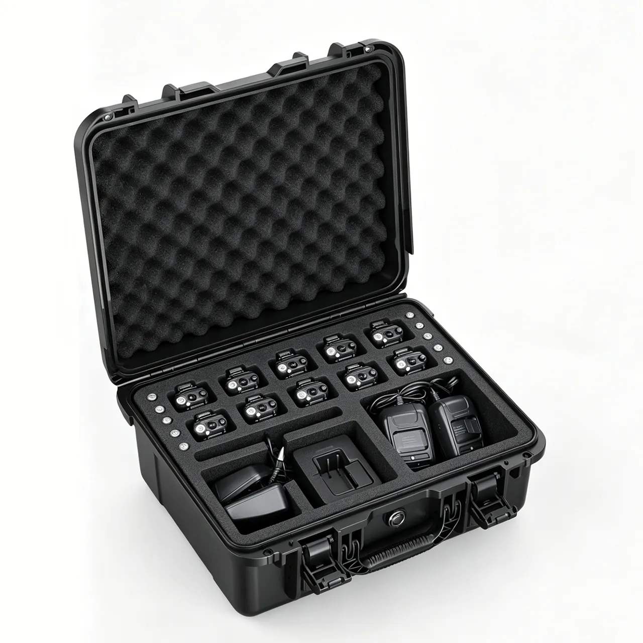
Packing the heavy parts. Lay fixtures along the long axis of the case with their combined centre of gravity near the geometric centre, and add straps or a clamping plate on top of the pocket so that lateral shock cannot roll a part out of position. The layout drawing and the pairing numbers go inside the lid.
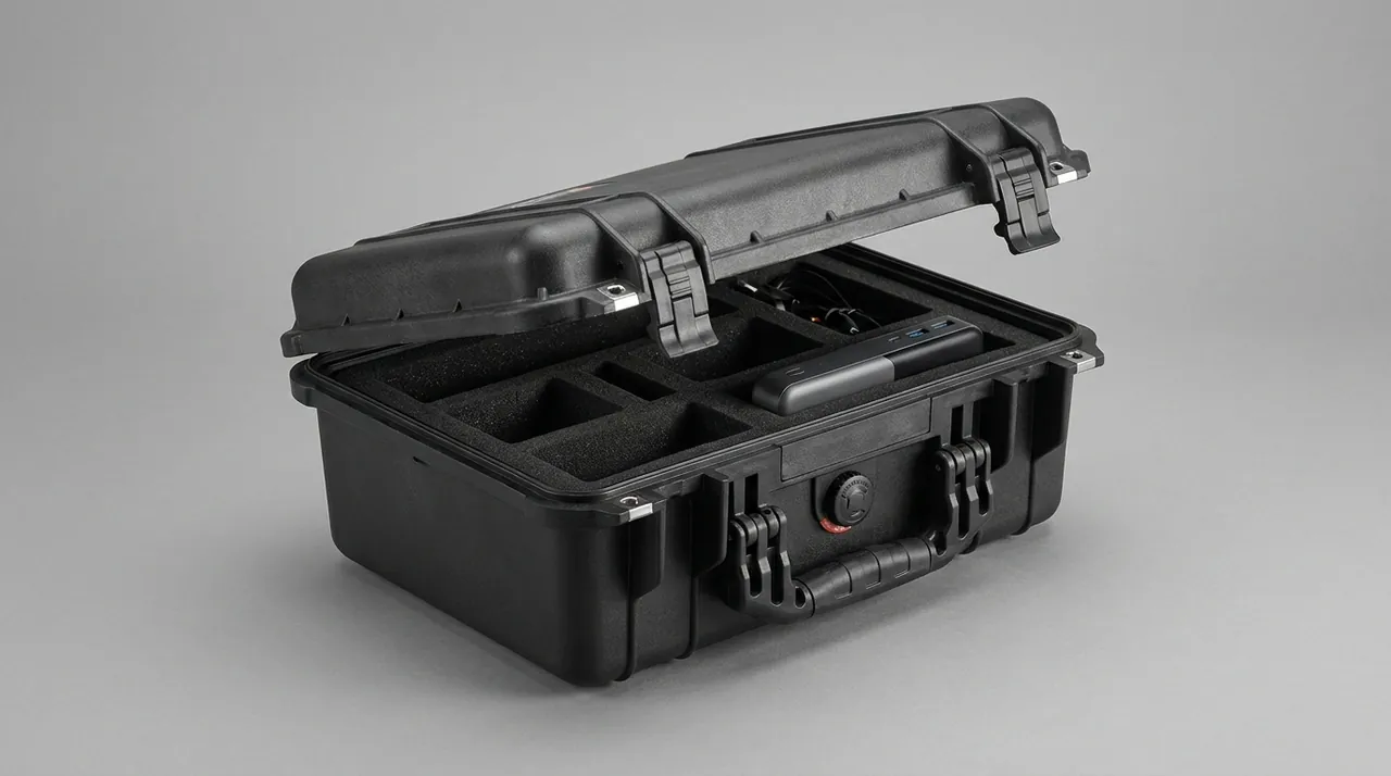
Packing the precision parts. Give the load cell and the extensometer a box-in-box arrangement, each with an ESD bag, desiccant and a humidity indicator card. The extensometer knife edge stays suspended so that it touches nothing at all.
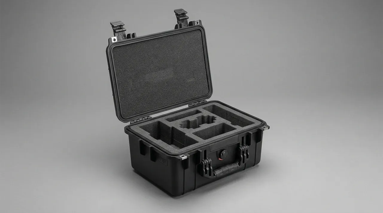
Final check before release. Work through the pairing numbers against the layout drawing one case at a time, confirm that every strap crosses a non-working face, that all latches are fully engaged and that the pressure equalization valve is clear, then write the seal number, packer and date onto the shipping document. Incomplete paperwork does not leave the warehouse.
Frequently Asked Questions
Q: Can the fixtures and sensors of a materials testing machine stay on the frame and ship as a complete machine?
A: It depends on the transport mode and distance. For short road legs with the original factory transport fixings in place, shipping assembled is acceptable. Removal and separate casing is advisable in three situations. First, ocean or intermodal transport, where the container interior is hot and humid for weeks and the frame cannot provide independent moisture and vibration protection for sensor surfaces and fixture working faces. Second, when the machine envelope and centre of gravity exceed general cargo limits and partial dismantling is required. Third, return to factory for verification or overhaul. Separate casing has a further benefit: each component can be given a sealing rating and liner matched to its own sensitivity, rather than forcing heavy fixtures and precision sensors to accept one packaging condition. When supporting testing machine customers, JUNZHJIA normally recommends a fragility grading pass first, listing fixture working faces, load cells and extensometers as must-case items while structural parts travel with the machine or in simplified packaging.
Q: Why should the tooth face of a wedge grip never be laid flat on foam?
A: Because the tooth face is the working contact surface of the fixture and the most geometrically sensitive feature on the whole assembly. When the tooth face presses directly on foam, the support is face contact with local hard points, and transport shock concentrates energy through the foam onto the tooth tips, causing chipping or micro-deformation. Foam debris and dust also embed between the teeth and degrade clamping consistency. The correct approach is a suspended pocket in the liner that lets the fixture carry its weight through non-working structural features while the tooth face touches nothing. In addition, upper and lower inserts are normally used as a matched, already-aligned pair, so keep them in one case with a pairing number to prevent mismatching that would introduce an alignment error. If the tooth face is already slightly damaged, check alignment and the grip surface before returning the machine to service. Record the finding in the fixture status card so that the next periodic geometric check has a reference point to compare against.
Q: Does a load cell need recalibration after transport, and what is the basis for deciding?
A: It depends on the circumstances and should not be generalised. If the shipment suffered a drop or obvious shock, or if the packaging is found damaged or showing moisture on opening, run a zero and indication check before putting the machine back into service. Even if the unit looks intact, if the sensor is used to produce test reports it is advisable to schedule an intermediate check. Established metrological practice is to arrange recalibration according to the applicable national verification regulation or calibration specification, that is the methods laid down in the JJG or JJF series documents. Different ranges and types correspond to different documents, so confirm the applicable one with a suitably qualified metrology body. If the laboratory operates to ISO/IEC 17025, update the equipment file and intermediate check plan after recalibration and reassess the validity of previously issued data. The decision rule most laboratories apply is simple: if the packaging shows no sign of abnormal shock or moisture, a routine intermediate check is sufficient; if there is visible packaging damage, go straight to a full recalibration.
Q: How should I choose between IP65 and IP67 cases for testing machine component transport?
A: The difference that matters is water. IP65 resists directed water jets; IP67 tolerates short immersion, typically 1 m for 30 minutes. Choose from the route rather than from a cost list. A domestic road journey with covered loading needs IP65, which is lighter and cheaper. Ocean freight, intermodal transfer, open quay storage or rain-exposed loading needs IP67. But the rating should be set per component group, not once for the whole shipment: hardened fixtures are mainly at risk from condensation rust, which IP65 with a vapour-phase inhibitor handles well, whereas a transducer that takes on moisture internally will drift and have to be recalibrated, so it belongs in an IP67 pocket with its own desiccant and antistatic bag. Two cautions apply. First, an IP rating says nothing about vibration, shock or drop performance, which have to be assessed against the GB/T 4857 series or ISTA. Second, a sealed case develops a pressure differential after a temperature change, so fit a pressure equalization valve for cross-climate or air shipments. Case mass also matters, because a heavier case is more likely to be dropped during a multi-floor laboratory move.
Q: How should metal fixtures and ball screws be protected against rust during ocean freight?
A: Build the protection in four layers, in this order. First, block the water: a case rated IP65 or above keeps rain and salt mist out. Second, block the air: put desiccant and a humidity indicator card inside the sealed volume, wrap irregular fixtures in vapour corrosion inhibitor film so they can be unpacked without wiping, and cover ball screw raceways with a dedicated sleeve or corrosion-inhibiting paper so they cannot be scored. Third, block the hand: clean machining debris off before packing and never touch a working face bare-handed, because the salt in a fingerprint starts a local corrosion cell. Roughly 20 to 50 g of desiccant per 30 to 50 litres of internal volume is a common starting point, and the quantity should be increased for ocean freight or journeys beyond a month. On arrival, do not open the case immediately; let it stand two to four hours in the unloading environment so that cold surfaces do not condense, then read the indicator card before inspecting working faces. If flash rust is found, record the packaging batch and assess whether geometric accuracy is affected rather than simply wiping it off.
Q: What usually goes wrong with ball screws in transport, and how should they be secured?
A: The main risk is bending, followed by the nut striking the end stops and damage to the raceway surface. A screw is a slender part with relatively low rigidity, and any lack of lateral support produces bending under vibration; once bent, the screw is effectively scrap and repair cost approaches replacement. Three fixing points matter. First, multi-point support: place enough supports along the screw length and avoid long unsupported spans. Second, nut locking: use a transport block or temporary lock to fix the nut position so it cannot travel to the ends and strike the stops. Third, surface protection: the raceway is a precision machined face and needs a dedicated sleeve or moisture-resistant paper wrap to prevent scoring and corrosion. When packing, lay the screw along the long axis of the case on the bottom layer and do not share a pocket with short items, so it cannot act as a lever under vibration.
Q: Why is a box-in-box arrangement recommended for extensometers?
A: Because an extensometer combines three features at once: small size, fine construction and sensitivity to contamination. The knife edge of a contact extensometer contacts the specimen directly, and chipping leaves a notch that causes unstable clamping and jumping readings. The flexure beam of a strain gauge extensometer has deliberately low stiffness, and external pressure causes permanent deformation that changes the calibration factor. On an optical extensometer, lens contamination or positional shift directly affects measurement. A box-in-box arrangement restrains the extensometer first in an individual small box and then places that box in a dedicated pocket, giving both independent vibration isolation and contamination protection, and making the unit easy to retrieve without opening the whole case repeatedly. Fit an ESD bag, desiccant and a humidity indicator card inside the small box, keep the knife edge suspended, and ship the calibration target or bar in the same case to avoid mismatching. Mark the small box with the extensometer serial number so that a laboratory running several machines cannot swap one box between them.
Q: Which transport tests should testing machine component cases be put through, and does MIL-STD-810H count as military certification?
A: Start from where the load spectrum comes from. A testing machine never moves inside the workshop, but its components have to hold geometric accuracy through road and sea legs, so the profile is taken from the worst leg rather than an average. The three component classes differ sharply. Wedge inserts and platens are heavy parts, so their energy sits in handling drops and stacking and the test set should include corner and edge drops. Extensometers and transducers are small precision items, so their energy sits in sustained random vibration and short high-frequency events, and acceleration transmission into the packaging should be measured. Ball screws are slender, so bending modes dominate and support spacing has to be checked, with an accelerometer at mid-span if there is doubt. The practical order is single-component vibration first, then a full loaded case drop, then a complete distribution cycle. After each one, open the case and re-measure fixture alignment and flatness, screw straightness and load cell zero, rather than judging by appearance. Cite the standards that apply: the GB/T 4857 series for drop and stacking, ISTA and ASTM D4169 for vibration and whole-journey simulation, IEC 60068 for controllers and drives. Quoting MIL-STD-810H means using its test methods; it does not mean the product holds any military certification or qualification, and reports should say so explicitly.
Conclusion & Related Reading
The difficulty with testing machine component packaging is that the pass criterion is not "it looks undamaged" but "the geometry and the metrological behaviour have not moved". Damage to a tooth face, a transducer flexure or an extensometer knife edge is measured in micrometres, so visual acceptance on arrival is close to useless. The design therefore has to do three things: suspend and lock the working faces, carry load along an unbroken path into the case floor, and hold moisture and heat outside the components.
Work through it as mark the working face, split the cases by working face and mass, set the rating and the rust preventive plan, trial fit and validate against the load spectrum, then arrive-measure geometry and zero before release. Five steps, and the re-verification and rework that follows a laboratory relocation or an equipment transfer drops sharply.
Related Reading