

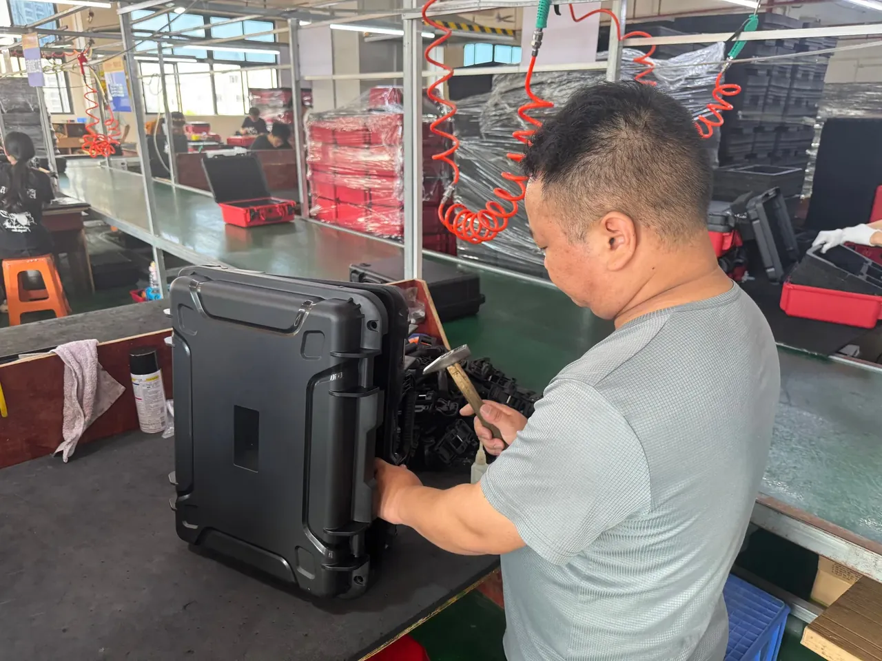
Quick answer: An Industrial caliper & gauge protective box fixes 8 base slots at ±0.4 mm under a 12 mm lid frame, keeping slot drift to 0.5 mm after a 1.0 m drop.
Table of contents
- Slot-width tolerance in the box bottom of an Industrial caliper & gauge protective box
- Lid press-frame height and the retained side clearance
- Step-slot displacement readings after six-face drops
- Press-frame sink judgement on the hinge-cycle rig
- Slot-width reject line for batch sampling
- FAQ
1. Slot-width tolerance in the box bottom of an Industrial caliper & gauge protective box
The insert in the box bottom carries 8 locating slots, and the ±0.4 mm slot-width tolerance starts the dimension chain. An Industrial caliper & gauge protective box has an inner cavity of 395×275×115 mm, the slots running along the long edge with each wall held by a moulded partition. Width cannot be loosened: side play after a gauge seats equals the gap between slot width and gauge width, so a tolerance past 1 mm pushes the stepped-slot reading beyond 0.5 mm at impact.
Trial moulds split the band into upper, nominal and lower slots on one tool, all 8 accepted at ±0.4 mm. Slot width is read at 20 ℃ to 0.1 mm, and any slot outside the band sends the tool back rather than being matched at assembly.
A locating slot is not standalone. With press-frame height and side clearance it forms one constraint: width governs left-right, the frame up-down, clearance front-back. Loosen any one and slot drift after a drop will not hold at 0.5 mm.
2. Lid press-frame height and the retained side clearance
An Industrial caliper & gauge protective box uses a 12 mm lid press-frame bearing on the foam pad above the gauge to remove vertical freedom. The 1.2 mm retained clearance is the net gap between frame edge and slot wall with the lid shut: a larger gap leaves front-back play, a smaller one makes the frame rub the wall and keeps the lid from seating.
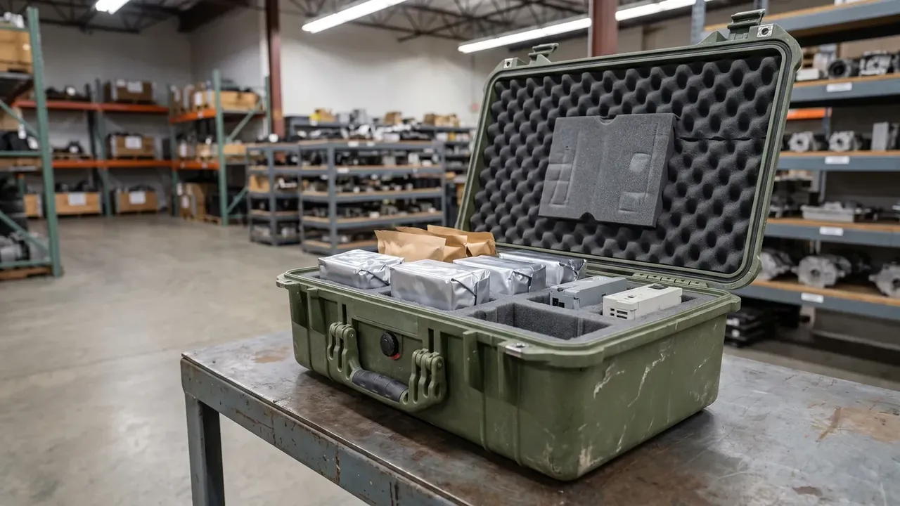
Frame stiffness needs its own check. A thin 12 mm frame fatigues at its root after 5000 hinge cycles, and a few tenths of a millimetre of sink eats into the 1.2 mm clearance. The table maps slot-width bands to frame settings.
| Slot-width band | Tolerance band | Frame match |
|---|---|---|
| 8.0 mm nominal | ±0.4 mm | Frame height 12 mm |
| 8.4 mm upper | ±0.4 mm | Retained clearance 1.2 mm |
| 7.6 mm lower | ±0.4 mm | Side-wall support recheck |
3. Step-slot displacement readings after six-face drops
Drops run at 1.0 m on six faces: bottom, top, two long sides and two short sides. An Industrial caliper & gauge protective box is loaded with 5.5 kg, the lid shut, and 2 catches each holding 310 N. Drift against the box floor is read on a scribed datum, with stepped slots measured at both the step edge and floor, neither past 0.5 mm.
| Drop orientation | Drop height | Slot drift |
|---|---|---|
| Bottom down | 1.0 m | ≤0.5 mm |
| Top down | 1.0 m | ≤0.5 mm |
| Long side A down | 1.0 m | ≤0.5 mm |
| Short side A down | 1.0 m | ≤0.5 mm |
An Industrial caliper & gauge protective box takes 0.5 mm as the drift line so the ±0.4 mm tolerance and 1.2 mm clearance keep reserve after impact. The box returns to room temperature for a second reading, confirming foam rebound has not shifted the slot. One sample from each end of the −10 ℃ to 55 ℃ range acts as control: the hot end is held 4 h before width is read, the cold end 4 h before clearance is read. Sealing is benchmarked to the IP65 method with no certificate number claimed, and any end pair diverging past 0.2 mm returns for an insert-bond recheck.
4. Press-frame sink judgement on the hinge-cycle rig
An Industrial caliper & gauge protective box runs 5000 open-close cycles at a fixed lid angle, with frame clearance read every 500 cycles. One judgement applies: the frame must not sink, meaning the 12 mm height still keeps clearance near 1.2 mm after 5000 cycles.
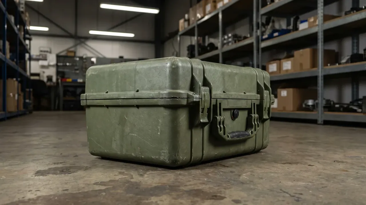
The rig also watches the catches, with sink banded below.
| Drift reading | Cycle count | Frame state |
|---|---|---|
| 0.2 mm | 5000 cycles | No sink |
| 0.3 mm | 5000 cycles | No sink |
| 0.5 mm | 5000 cycles | Boundary |
| 0.6 mm | 5000 cycles | Reject |
The 310 N holding force of each of the 2 catches decays across 5000 cycles; once low enough the lid seats unevenly and sink readings inflate. Force is remeasured every 1000 cycles and plotted against clearance in one log.
5. Slot-width reject line for batch sampling
An Industrial caliper & gauge protective box has all 8 slots per shot checked at ±0.4 mm. Reject is set on the spread across the 8 slots of one shell, not on a single slot: a spread past 0.4 mm sends the tool back, since uneven mould shrinkage splits impact loads. Outer 430×310×150 mm and inner 395×275×115 mm are remeasured, and the 3.0 mm wall must show no local thinning.
Batch rejection looks at one whole shell, not at the best piece.
Conclusion
An Industrial caliper & gauge protective box builds its dimension chain from the ±0.4 mm slot tolerance of 8 base slots, closes it through a 12 mm lid frame and 1.2 mm clearance, and lands on ≤0.5 mm slot drift after a 1.0 m six-face drop. A 5000-cycle rig adds the no-sink recheck, while 2 catches at 310 N each and sealing benchmarked to IP65 hold one set of readings across −10 ℃ to 55 ℃. Batch sampling puts reject on the spread of 8 slots, so uneven shrinkage stops before assembly.
Related Reading
- Measuring tool case selection basics
- Gauge block case insert layouts
- Metrology standard case sealing
- Field inspection equipment case stacking specs
Related Products
- 8 Series — Gun Cases; Military Equipment Cases; Camera Equipment Cases; Drone Cases; Watch Cases; Knife Cases; First Aid Cases; Electronics Equipment Cases
- WL8-2812 PP Gun Case — model WL8-2812
- All protective cases and toolboxes: 7 series, 158 models