

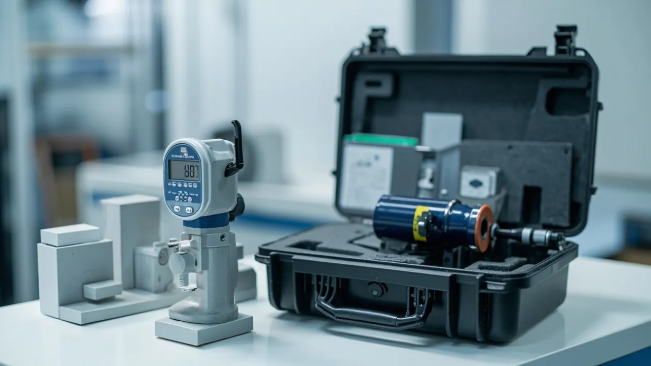
Metrology reference standards and gauge blocks exist for the accuracy they carry, so the goal of transport protection is not "undamaged" but "unchanged". A gauge block with a fine score on its wringing face, a standard resistor that has taken a thermal shock, a force standard transducer that has seen one over-threshold vibration, may all look perfect on arrival while the value they realise has already moved. The conclusion is direct: reference standards and gauges must travel in a purpose-built case with custom foam, controlled temperature and humidity, verified vibration isolation and provision for sealing. An ordinary tool box or generic flight case is not an acceptable substitute.
The defining property of a reference standard, whether a gauge block, standard resistor, standard cell, standard weight, torque standard or force standard transducer, and of a gauge such as a micrometer, caliper, ring gauge, plug gauge or dial indicator, is traceability of value. When a transport anomaly occurs, the response is not a simple re-check. It is a decision, made against metrological rules, about whether re-verification or recalibration is needed and whether the calibration results already issued remain valid. For a calibration laboratory operating to ISO/IEC 17025, that decision reaches into the equipment file, the intermediate check plan and the validity of certificates already in the field.
This article is written for equipment managers in metrology institutes, heads of corporate metrology rooms, operations staff in third-party calibration laboratories, and the procurement and logistics people who arrange gauge transfers and submissions for calibration. It breaks down the fragile points of measuring instruments, the temperature and humidity control a case must provide, vibration isolation design, liner material trade-offs, the transport test standards that apply, and an acceptance method that can be written into the submission procedure.
Table of Contents
- 1. Why Reference Standards Need a Purpose-Built Case
- 2. Instrument List and Fragility Grading
- 3. Gauge Block Protection: Wringing Faces, Stability and Temperature
- 4. Standard Resistors, Standard Cells and Electrical Standards
- 5. Force Standard Machines and Transducers: Vibration First
- 6. Torque Standards and Torque Wrench Calibrators
- 7. Temperature Standards: Standard PRTs and Bath Components
- 8. Length Standards: Ring Gauges, Plug Gauges and Precision Gauges
- 9. Temperature and Humidity Stability: In Transit and On Arrival
- 10. Liner Design: EVA, PE, PU and Low-Outgassing Materials
- 11. Sealing Tiers for Reference Standards and Gauges
- 12. Test Basis and Acceptance Criteria for Reference Standards
- 13. Identity Marks, Metrological Status Labels and Tamper Evidence
- 14. Selecting and Releasing a Reference-Standard Case
- Frequently Asked Questions
- Conclusion & Related Reading
1. Why Reference Standards Need a Purpose-Built Case
The fundamental difference between a measuring instrument and an ordinary industrial component is that its value lies not in structural strength but in the stability of the quantity it realises. A motor that has been knocked announces itself with noise or heat. A standard resistor that has absorbed moisture may shift by a very small proportion, and the change may not be noticed until the next calibration cycle, while every value transferred through it in the meantime carries a systematic bias.
Transport affects measuring instruments through three mechanisms:
- Mechanical. Shock and vibration score wringing faces, leave residual deformation in a standard's support structure, produce residual strain in a transducer elastic body, and damage precision threads and fits. Most of this is irreversible.
- Thermal. A rapid temperature change alters dimensions and redistributes internal stress. For a gauge block, whose thermal expansion coefficient enters the value calculation, a high or low temperature experienced in transit is itself a form of condition contamination. An abrupt change can also cause condensation.
- Chemical and hygroscopic. Moisture, salt mist, plasticiser outgassing and dust all change surface condition. Electrical standards and optical gauges are especially sensitive.
A purpose-built case performs four functions here:
- Geometric locking. The instrument stays in its designed attitude and cannot collide with a neighbour or shift inside the case.
- Thermal buffering. Case structure and liner slow the rate at which the internal temperature rises or falls.
- Environmental isolation. Sealing and desiccant block moisture, salt mist and dust.
- Traceable status. A security seal, labels and unboxing records turn "was the transport abnormal" into a determinable fact.
The approach JUNZHJIA uses with metrology customers is to grade instruments by value sensitivity first, then fix the case specification, liner structure and whether a thermal barrier or vibration isolation layer is needed, and finally configure the seal and status labels to suit the submission process. That sequence avoids expensive mistakes of the kind that look convenient at the time, such as shipping gauge blocks and wrenches in the same case.
2. Instrument List and Fragility Grading
There are many kinds of measuring instrument, but the fragile points fall into a stable set of categories. The table below can be used directly to draft a packaging work instruction for submissions and transfers.
| Instrument category | Typical items | Primary failure mode | Sensitivity | Recommended protection |
|---|---|---|---|---|
| --- | --- | --- | --- | --- |
| End standards | Gauge blocks, thin blocks, accessories | Wringing face scoring, dimensional change, corrosion | Very high | Dedicated gauge block case, desiccant, thermal barrier |
| Electrical standards | Standard resistor, standard cell, divider | Resistance drift, EMF change, insulation loss | Very high | Individual pocket, ESD, sealed case |
| Force standards | Force standard transducer, proving ring | Elastic body residual strain, zero drift | Very high | Individual pocket, vibration isolation, upright attitude |
| Torque standards | Torque standard, wrench calibrator | Elastic shaft residual deformation, key damage | Very high | Upright support, vibration isolation |
| Temperature standards | Standard PRT, standard thermocouple | Lead damage, sheath deformation, annealing drift | Very high | Individual tube pocket, vibration isolation, straight storage |
| Length gauges | Ring gauge, plug gauge, micrometer, caliper | Working face scoring, spindle damage | High | Zoned liner, rust prevention |
| Indicating gauges | Lever indicator, dial indicator | Mechanism de-calibration, stylus damage | High | Individual soft wrap, vibration isolation |
| Mass standards | Standard weights | Surface scoring, mass change, especially at high class | High | Individual pockets, dust protection |
| Support equipment | Temperature logger, display unit | Board moisture, terminal loosening | Medium | ESD protection, desiccant |
The critical action after grading is one drawing and one position per instrument. Every case needs a liner layout drawing that records the instrument name, identification number, class and removal sequence for each pocket. For gauge block sets, note the set number and any missing items so that counting on site cannot be misjudged.
Note in particular that instruments of different sensitivity should not be mixed in one case. Gauge blocks with wrenches, or weights with calipers, will interact hard against hard under vibration. Where mixed transport is unavoidable, separate them physically with layers and dividers rather than simply adding more foam thickness.
3. Gauge Block Protection: Wringing Faces, Stability and Temperature
Gauge blocks are the foundation end standard, and their defining property is wringing: two blocks in clean condition adhere closely face to face. Wringing depends on extreme flatness and surface finish, and any score, corrosion or adsorbed contamination destroys it.
Four protection essentials for gauge blocks:
- Wringing faces must never carry load and never rub. Inside the case, blocks should either not touch each other at all or be separated by dedicated interleaving paper and low-outgassing foam. Stacking is prohibited, and sharing a pocket with metal tools is prohibited.
- Rust prevention comes first. Gauge block material is highly sensitive to humidity and to the salt in fingerprints. Clean and apply rust preventive treatment before packing, and use a vapour phase corrosion inhibitor. Avoid bare-hand contact with working faces.
- Thermal buffering. Gauge blocks participate in value correction through their thermal expansion coefficient, so high temperatures in transit matter. More important still is the rate of change: rapid warming creates a temperature gradient between the surface and the interior, which lengthens the time needed to reach equilibrium before wringing. The case and liner should therefore provide some thermal resistance, following the approach outlined in protective case design for extreme temperatures.
- Equilibration on arrival. Do not verify immediately. Established practice is to let the blocks stand in the verification room until thermal equilibrium is reached; the time depends on block size, set size and the temperature difference. Small single blocks need less time, while a full case of large blocks needs considerably more. The criterion is reaching the temperature stability the verification environment requires, not a fixed number of hours.
Case structure recommendations:
- Use a layered tray arrangement, one group of blocks per layer, with a soft interlayer between trays.
- Give each block a semi-open pocket that allows easy removal without lateral compression.
- Fit desiccant and a humidity indicator card, and paste the instrument list and set number inside the lid.
- Thin blocks, which bend easily, should lie flat with light compression to prevent warping.
Metrology note. Gauge blocks should be re-verified according to the applicable national verification regulation or calibration specification, that is the method laid down in the relevant JJG or JJF series document. Different classes and size ranges correspond to different documents, so confirm the applicable document and interval with a suitably qualified metrology body.
4. Standard Resistors, Standard Cells and Electrical Standards
Electrical standards are sensitive in value to temperature, humidity and mechanical stress, and standard resistors and standard cells are the most demanding on temperature.
Standard resistors:
- Resistance changes with temperature according to a defined temperature coefficient. High temperatures in transit alter the internal stress state, and some types need a long recovery period before they are stable again.
- Mechanical shock should be avoided. The winding structure can shift slightly under shock, producing a small permanent resistance change.
- Pack in ESD-safe material to protect the associated measuring circuit; see ESD shield case design points.
Standard cells:
- Extremely sensitive to tilt and vibration. Keep them upright in transit, never inverted and never shaken.
- Thermal shock affects the electromotive force significantly and recovery is slow.
- Do not ship in the same case as a strong magnetic source or a vibration source.
Dividers, standard capacitors and instrument transformers:
- Larger units need base load plates sized for their own weight.
- Oil-filled standards require confirmed sealing and leak protection, and must be kept upright.
General packaging points:
- ESD. Bag or cushion every electrical standard in ESD-safe material.
- Moisture. Sealed case with desiccant and a humidity indicator card.
- Vibration. Individual pockets with low-density compliant material, no hard points.
- Attitude. Follow the manufacturer's stated attitude; standard cells and some oil-filled instruments must stay upright.
A common mistake is to stack several electrical standards in one case separated only by a layer of bubble wrap. The risk is not compression but relative sliding: under vibration the two instruments rub against each other, which can both mark surfaces and introduce an invisible static charge effect on the instrument.
5. Force Standard Machines and Transducers: Vibration First
Force standard machines and their transducers are among the most vibration-sensitive instruments in metrology. They work by the repeatable deformation of an elastic body under load, and any acceleration above the threshold can introduce irreversible residual strain.
Vibration isolation works at three levels:
- Case level. The case needs enough stiffness and damping to avoid amplifying resonance in the transport frequency band. Longitudinal ribs and appropriate wall thickness achieve this.
- Liner level. Use a layered structure: a high-density EVA base plate for load bearing and a PU or soft EVA layer for conformity, creating an impedance mismatch that reduces energy transfer to the instrument.
- Instrument level. Contact between transducer and liner should be face contact rather than point contact, avoiding local stress concentration.
Attitude and support requirements:
- Column and pancake transducers should be placed in the attitude specified by the manufacturer. Where horizontal placement is permitted, the load axis should be parallel to the case base so self-weight does not act on the measuring direction over a long period.
- The base of the transducer needs flat support and must not be carried by any pointed feature.
- Adapters, load buttons and spherical seats go in a separate zone and must never rest on the transducer.
Cables and connectors:
- Transducer cables are usually shielded multicore and need a dedicated coiling channel with a radius at least ten times the cable outer diameter.
- Fit protective caps on connectors and restrain them so they take no load in transit.
- Where a transducer has built-in amplification or digital output, treat it as an electrical component as well, with moisture and ESD protection.
Metrology note. Force standard machines and proving instruments should likewise be re-verified according to the applicable national verification regulation or calibration specification. If the shipment suffered a drop or an obvious shock, do not put the instrument straight back into service; run a zero and indication check first and then decide whether to submit it for verification. For a laboratory operating to ISO/IEC 17025, recalibration should be followed by an update to the equipment file and intermediate check plan and a reassessment of the continuing validity of earlier calibration results. Where a shipment combines force transducers with precision fixtures, the isolation logic in shock and vibration isolation case design can be reused directly, including the layered liner and strap plate arrangement.
6. Torque Standards and Torque Wrench Calibrators
Torque standards, including torque standard machines, standard torque wrenches and torque transducers, derive their value from torsional deformation of an elastic shaft. Their isolation and anti-bending requirements resemble those for force transducers, with one addition: protection against torsion.
Protection points:
- No axial compression. A torque transducer must not carry axial compression in transit, which would shift the strain gauge zero.
- Square drive and keys. The square drive or keyway is a fit, and damage increases connection clearance and therefore measurement error. Fit protective sleeves.
- Upright support. Some torque standards require upright transport. Provide a located upright seat in the liner and secure it with a strap plate.
- Avoid cantilever. The long arm of a torque wrench calibrator forms a cantilever in transit and can deform plastically. Add intermediate supports to shorten the unsupported span.
- Levers and weights. These are accessories and go in a separate zone, never resting on the transducer body.
Packing sequence. Lay long arm structures along the long axis of the case with mid-span support. Place the transducer body in its individual pocket. Place levers, weights and connectors in layers from heaviest at the bottom upward.
When JUNZHJIA builds custom liners for metrology customers, the standard request is a three-view drawing or photographs of the instrument, plus a clear statement of which faces may be touched and which must never be touched. For instruments with a long arm and a directional requirement, such as a torque standard, the liner drawing marks both the axial and rotational locating features so that the instrument cannot be fitted the wrong way round on site.
7. Temperature Standards: Standard PRTs and Bath Components
Temperature standards include standard platinum resistance thermometers, standard thermocouples, standard liquid-in-glass thermometers where permitted, and the removable components of calibration baths and dry block calibrators.
Standard platinum resistance thermometers:
- The sensing element is high purity platinum wire whose resistance-temperature relationship has been carefully characterised. Mechanical shock changes the stress state of the wire and shows up as drift in R0 or in the temperature coefficient.
- The quartz or glass sheath is fragile and must not take bending or compression.
- The leads are four-wire, fine and brittle. Provide a dedicated storage channel so they cannot tangle or be repeatedly flexed.
- Keep the sheath straight in the case and away from any hard object.
Standard thermocouples:
- After high temperature use, the electrodes drift through oxidation and contamination, so transport must prevent bending and contamination.
- Protecting the measuring junction and the reference end matters particularly; use the dedicated protective sleeve.
- Handle used thermocouples carefully and do not put them in the same pocket as new ones, which causes contamination.
Removable bath and dry block components:
- Stirrers, heaters and uniformity baffles are often heavy metal parts and need an individual load-bearing pocket.
- Components carrying oil or fluid should be treated as wet parts, with oil-resistant liner and a barrier film at the base of the case.
- Seals and gaskets are consumables; pack them separately rather than leaving them compressed.
Temperature and humidity control. The real risk with temperature standards is not drift in transit but verification before equilibration. Any temperature standard should reach thermal equilibrium under its stated reference conditions before use. In practice, record the extreme temperatures seen in transit and the ambient temperature on arrival, and set the equilibration time from those figures rather than copying a fixed duration.
8. Length Standards: Ring Gauges, Plug Gauges and Precision Gauges
Ring gauges, plug gauges, micrometers and calipers are usually of lower metrological class than gauge blocks, but they share one property: once a working surface is damaged, the gauge is finished.
Ring and plug gauges:
- The working surface is cylindrical or threaded, and scoring causes a direct deviation in size judgement. Use protective sleeves or individual pockets so nothing metal touches them.
- Large ring gauges are heavy and need a load-bearing pocket plus a lifting point in the case.
- The thread form of a thread gauge is especially fragile and must not contact hard material.
Micrometers and calipers:
- The spindle and anvil are the core working faces. Ship with the measuring faces separated so they are not held closed under load for long periods.
- The frame should lie flat rather than being held in a bend.
- The display of a digital caliper is electrical and needs moisture protection.
- A box-in-box arrangement is recommended: keep the original manufacturer packaging inside the protective case, gaining both the original locating accuracy and the case's mechanical and environmental protection.
Lever and dial indicators:
- The stylus and lever mechanism are the weak points and lose calibration under vibration. Use a cushioned pocket and ship with no pre-load.
- The bezel glass is fragile and must not be compressed.
Rust prevention. The working faces of length gauges are precision machined. Apply rust preventive treatment and desiccant for ocean freight or in hot humid climates, and clean before packing so no fingerprints remain.
9. Temperature and Humidity Stability: In Transit and On Arrival
For a measuring instrument, transit is not a period outside metrology; it is a blank segment in the value chain. Controlling that segment takes two actions: control in transit and recovery on arrival.
In-transit measures:
- Thermal barrier. Add a layer of low-conductivity material inside the case to slow the rate of internal temperature change. On routes with a large day-night swing, this layer is worth more than extra structural foam.
- Phase change modules. For extremely temperature-sensitive instruments, a phase change material module can hold the internal temperature within a narrower band. Confirm the module's temperature range and the handling required on arrival.
- Temperature logger. Place a single-use or readable logger inside the case to record the full temperature profile. This is the most direct evidence for judging whether the transport was abnormal.
- Sealing and desiccant. Block external moisture and control the initial internal moisture load. Budget roughly 20 to 50 g of desiccant for every 30 to 50 litres of internal volume, doubling it for long journeys or the humid season.
- Condensation control. Do not open the case immediately when moving from a cold environment into warm humid air. Let it stand two to four hours and check the humidity indicator card first.
Recovery on arrival:
- Check the seal and external appearance first, then the humidity indicator card and the logger data.
- Let the instrument reach thermal equilibrium in the verification room before verification. The time depends on size, material and the temperature difference.
- For gauge blocks, whose thermal expansion enters the value correction, confirm the temperature has stabilised to the verification environment requirement before starting.
- If the logger shows the instrument exceeded its permitted transport conditions, state that explicitly in the submission request so the metrology body can decide whether to shorten the interval or add check items.
An easily missed detail: do not place the temperature logger in direct contact with the instrument. Put it where it represents the internal air temperature, otherwise it records the contact point rather than the environment and its value as evidence falls away.
10. Liner Design: EVA, PE, PU and Low-Outgassing Materials
Measuring instruments impose higher demands on packaging material than general industrial parts, chiefly because material outgassing can contaminate a surface or a sensing element.
| Material | Density | Resilience | Processing | Suited to | Notes |
|---|---|---|---|---|---|
| --- | --- | --- | --- | --- | --- |
| EVA, low outgassing grade | Medium to high | Good | CNC routing, heat pressing | Gauge block cases, weights, standard bodies | Dimensionally stable, complex pockets |
| PE, expanded | Low | Moderate | Die cutting, lamination | Filling, light part protection | Low cost, collapses under long compression |
| PU, polyurethane | Low to medium | Excellent | Die cutting, CNC | Transducers, irregular precision parts | Good conformity, confirm outgassing grade |
| XPE / IXPE | Low | Good | Die cutting, lamination | Thermal barrier layers, base pads | Common for layering and buffering |
| Acid-free interleaving paper | Not applicable | Not applicable | Slitting | Gauge block wringing faces, optical faces | No acidic content, avoids corrosion |
Design points:
- Layered structure. High-density EVA base load layer, EVA or PU locating layer with routed pockets, low-density PE or XPE compression layer on top, and an optional IXPE thermal barrier.
- Clearance control. Aim for 1 to 2 mm between pocket and instrument. Too much and it accelerates inside the pocket under vibration; too little and loading is difficult and compressive stress rises.
- Hard point avoidance. Never let a square foam edge press on a gauge block wringing face, a transducer diaphragm, a glass sheath or a bezel glass.
- Material cleanliness. Prefer low-outgassing, low-particle-shedding grades. Ordinary recycled foam releases organic compounds that are unfriendly to electrical standards and optical gauges.
- Cleanability. The liner should be removable for cleaning so dust does not accumulate over years of use.
Behaviour over years is compared in case foam material comparison; the routing and pressing route for a custom liner, and the mistakes that recur, are set out in the custom foam insert design guide.
11. Sealing Tiers for Reference Standards and Gauges
One sealing tier for the whole shipment does not work for measuring instruments, because their failure mechanisms differ: steel gauges suffer surface pitting, electrical standards suffer moisture in their insulation, and force and torque standards are threatened less by water than by vibration. In addition, the sealing cavity for gauge blocks and standards must make it easy to verify the last verification or calibration status and validity on arrival, so that sealing and verification traceability stay in step. That is the extra requirement that sets measuring instruments apart from ordinary industrial parts.
Steel gauges — gauge blocks, ring gauges, plug gauges, anvils — fear rust and oxidation rather than flooding. Once a wringing face pits or oxidises, both wringing and dimensional stability fall away, and the damage is effectively permanent. The threat is condensation, the salt in fingerprints and the slow oxidation of long-term sealed storage, not standing water. The priority for this class is case sealing plus a vapour-phase inhibitor and an anti-oxidation barrier, and IP65 covers it unless the consignment spends a night on an open dock.
Electrical standards — standard resistors, standard cells, standard capacitors — fear moisture reaching the insulation and the terminals. Insulation resistance falls and temperature coefficients shift, and how far the value has moved can only be established by recalibration; it cannot be judged on site. Treat these as IP67 and place desiccant and antistatic packaging in an individual pocket, so that the case and the instrument provide two independent sealing levels.
Force and torque standards and force transducers fear vibration and shear shock. The ingress rating is close to irrelevant for them, and the isolation scheme has to be assessed separately along the lines of the next section. Raising the IP rating will not solve their problem.
| Instrument class | Dominant failure mechanism | Target rating | Additional measures |
|---|---|---|---|
| --- | --- | --- | --- |
| Gauge blocks, ring and plug gauges | Wringing face pitting, loss of dimensional stability | IP65 | VCI film, acid-free interleaving paper, layered trays |
| Standard resistors, standard cells | Falling insulation resistance, greater temperature drift | IP67 | Desiccant, ESD bag, upright attitude as specified |
| Force standard machines and transducers | Residual strain in the flexure causing zero shift | Set by the isolation scheme | Face-contact support, multi-axis restraint |
| Torque standards, torque wrench calibrators | Change in lever ratio, indication drift | IP65 | Rigid dividers, shaft-end sleeves |
| Temperature loggers, indicating instruments | Moisture and dust | IP65 | Desiccant, interface caps |
What each digit of an IP code means, and where the practical boundary between IP54 and IP68 lies, is general material that is not repeated here; see ingress ratings and standard definitions. This section answers only which tier a measuring instrument needs.
Two mistakes recur. The first is choosing on case rating alone and ignoring rust prevention and static control inside it: however tight the case is, the air sealed in with the instrument already carries water. The second is specifying the highest tier "for safety", when the extra self-weight raises the chance of a drop during a multi-floor move.
Where a calibration submission route involves air freight or crosses climate zones, fit a pressure equalization valve so that excessive opening resistance does not lead users to lever the case open and damage the gasket; see the role and selection of case pressure equalization valves.
12. Test Basis and Acceptance Criteria for Reference Standards
The acceptance criterion for a measuring instrument is not "the case survived" but "the indicated value has not moved". Test items should therefore be matched to the failure mechanism of the instrument rather than copied from a general list.
| Failure mechanism | Corresponding test clause | Must be re-checked afterwards |
|---|---|---|
| --- | --- | --- |
| Wringing face chipped in a handling drop | GB/T 4857 drop clauses | Wringing, flatness |
| Gauges compressed under long-term stacking | GB/T 4857 stacking clauses | Dimensional stability, liner compression set |
| Residual strain in flexures under sustained vibration | ISTA or ASTM D4169 vibration clauses | Zero, indication |
| Electrical standards drifting after thermal shock | IEC 60068 temperature and humidity clauses | Insulation resistance, indication |
| Whole submission route | ASTM D4169 distribution cycle | Combined judgement |
A workable order is a single-item packaging vibration test to confirm the liner and the restraint, then a fully loaded case drop to confirm the case structure, then one complete distribution cycle simulation along the real submission route. Open the case after each of the three and re-check wringing on gauge blocks, zero on force transducers and indication on torque calibrators, rather than judging by appearance alone.
The transport packaging and environmental test standards in common use — the GB/T 4857 series, the ISTA series, ASTM D4169, IEC 60068 and the method parts of MIL-STD-810H — lie outside the scope of this article. The clauses most often cited in domestic submission and transfer contracts are set out in GB/T 4857 transport packaging essentials, and the way test items are combined along a real route is covered in ASTM D4169 distribution cycle testing. One point needs stating explicitly: quoting MIL-STD-810H means adopting its test methods, and it does not mean the product holds any military certification or qualification. That wording belongs in the test report and in the commercial documents.
13. Identity Marks, Metrological Status Labels and Tamper Evidence
A case used for a calibration submission has to carry two kinds of information that ordinary equipment cases do not: what the instrument is, and where it stands metrologically.
Identity and status marking:
- Asset and set number. The instrument number and, for grouped items such as gauge block sets or weight sets, the set number and a statement of completeness, so that a missing piece is not mistaken for a calibration failure on site.
- Metrological status. Last verification or calibration date and its validity, the accuracy grade, and the date of the next intermediate check, so that the laboratory can plan by interval rather than by memory.
- Prohibited contact surfaces. Wringing faces, measuring faces and diaphragms are marked on the layout drawing so that packing staff know what must not touch anything.
- Handling marks. Net and gross weight, stacking limit, this-way-up and keep-dry symbols, with the specified attitude for standard cells and oil-filled instruments called out separately.
Seals and tamper evidence. For instruments going out for calibration, a single-use seal or tamper-evident label turns "was the transport normal?" from an opinion into evidence. Record the seal number on both the submission form and the case label, check it before opening, and keep photographs of the unsealing.
Flammability and materials. UL94 declarations cover the plastic trays, foam and label materials inside the case, not the instruments themselves. Where a laboratory operates to ISO/IEC 17025, the marking scheme should also let the equipment record be cross-referenced quickly, since a relocation is a change that can affect the validity of results. Assembly detail for the case hardware is covered in toolbox hinges, latches and seals explained.
14. Selecting and Releasing a Reference-Standard Case
Condensing the previous thirteen sections into an executable sequence gives seven steps, and the first three determine everything that follows.
Step one: build the instrument list. Record name, number, quantity, accuracy grade, envelope dimensions, mass, sensitivity class and whether the instrument carries liquid. Step two: fix the case type and count. Split by sensitivity and size, following the rule that primary standards travel alone and gauges travel by class. Step three: decide sealing and thermal protection. Choose the tier from the transport route and decide from the temperature swing whether an insulating layer and a phase-change module are needed. Step four: design the liner. Layer the structure, draw the layout and mark the removal sequence together with the faces that must not be touched. Step five: sample and trial fit. Trial fit with the real instruments and check clearance, access, correct attitude and strap effectiveness. Step six: validate and seal. Run the transport simulation, fit the logger, desiccant and seal, and write the seal number into the record. Step seven: accept and recover. Check the seal, read the indicator card and the temperature record, and let the instruments equalise before sending them for calibration.
Checklist to write into the purchase contract:
| Check item | Method | Acceptance criterion |
|---|---|---|
| --- | --- | --- |
| Seal and seal number | Check the number and the case exterior before opening | Number matches, seal intact |
| Humidity indicator card | Read before opening | Card has not changed colour |
| Temperature record | Download the logger curve | Never outside the permitted transport conditions |
| Prohibited contact surfaces | Visual plus gloved touch | Wringing faces, measuring faces and diaphragms show no contact marks |
| Sealing performance | Air tightness test or immersion sampling | Meets the declared IP rating |
| Attitude | Compare against the layout drawing | Upright or flat orientation as specified |
| Thermal protection and logger | Document review | Logger count, position and reading method defined |
| Barcode and QR code | Scan | Content correct, code readable |
| Instrument count and completeness | Compare against the list and set number | Nothing missing, set complete |
Support available from JUNZHJIA. Cases for calibration submissions are built by Kexin New Materials (Guangdong) Co., Ltd. under the JUNZHJIA brand, working from the customer's instrument list: liners are laid out by sensitivity class and by the attitude each instrument must travel in, OEM and ODM branding is supported, and specifications, layout drawings and batch inspection records can travel with the shipment. Institutions with a fixed submission route can build a standard case library using the approach in the instrument and equipment case selection guide; supplier screening points are collected in how to choose a protective case OEM factory.
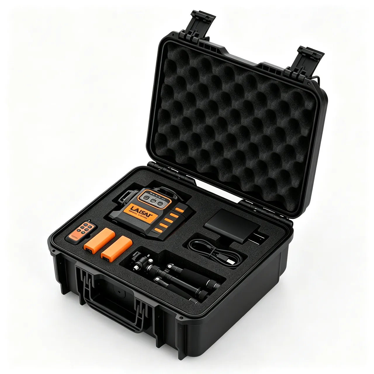
Gauge block packing. Use layered trays, one group per layer, separated by soft interlayers. Keep wringing faces suspended or in contact only with acid-free interleaving paper. Fit desiccant and a humidity indicator card, and paste the set number and list inside the lid.
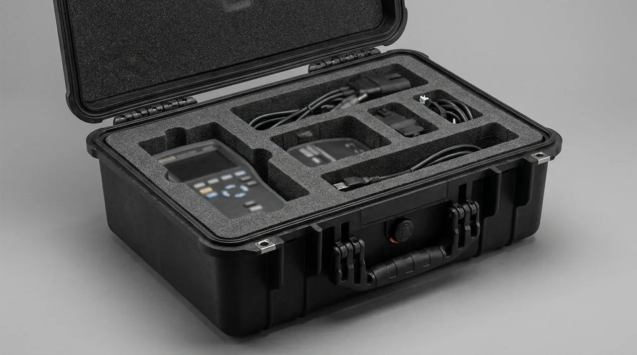
Temperature standard packing. Keep the sheath straight and isolated from hard objects, route the four-wire leads into a dedicated channel to prevent tangling, and cap the connectors. The pocket floor should be flat support rather than point support.
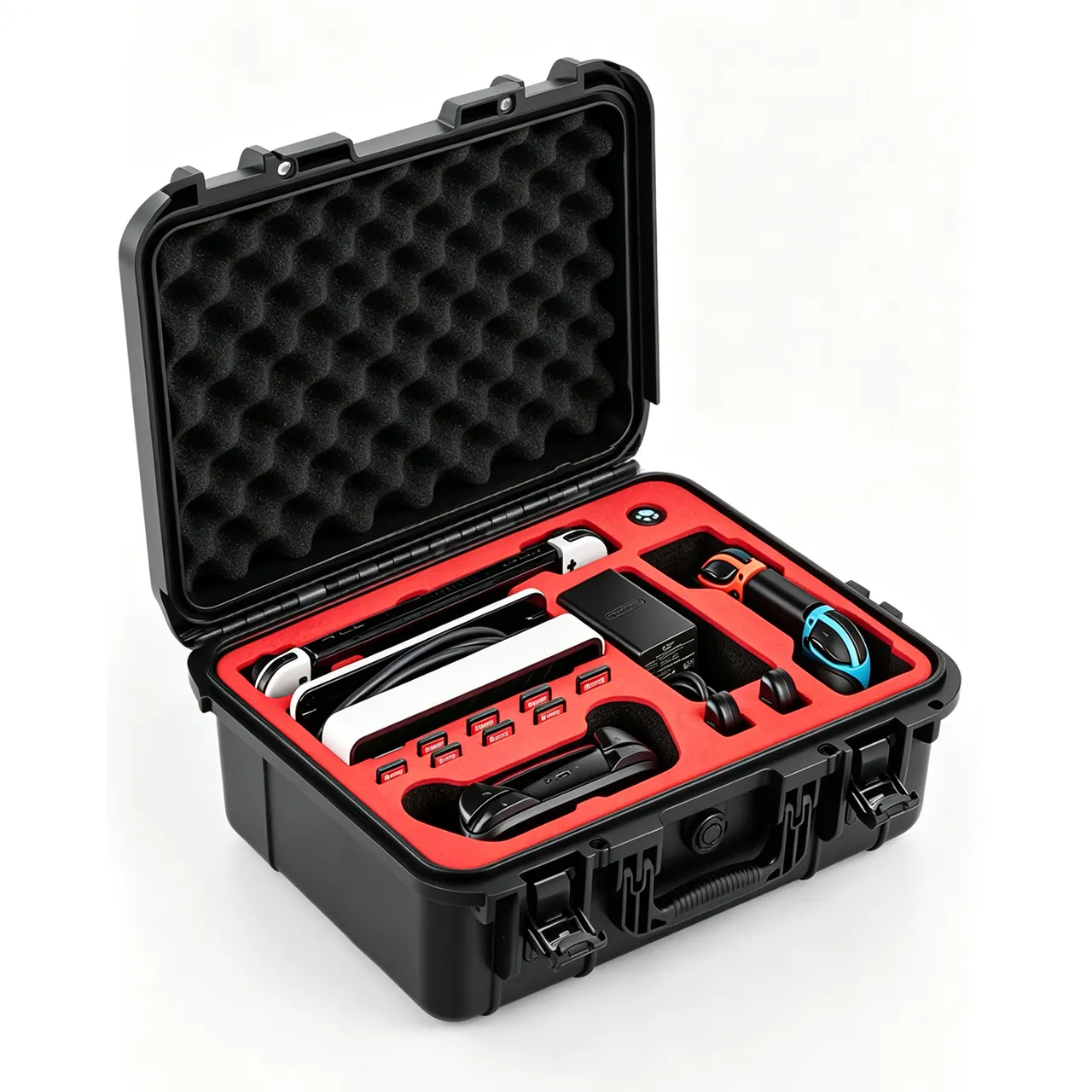
Final check before release. Count the instruments and set numbers against the list, confirm the logger is running, the desiccant and indicator card are in place and every latch is fully engaged, then fit a single-use seal and copy the seal number onto the submission form. A shipment without a recorded seal number does not leave the store.
Frequently Asked Questions
Q: Can gauge blocks be shipped in an ordinary tool box, or is a dedicated gauge block case really necessary?
A: An ordinary tool box is not advisable. The defining property of a gauge block is wringing, which depends on extreme flatness and surface condition. A tool box fails in three ways. First, it has no locating structure for gauge blocks, so they slide inside and strike the case wall or other tools. Second, its liner is usually recycled foam or rubber, which releases plasticisers and sulphur compounds that form an organic film on the metal surface, harming both wringing and corrosion resistance. Third, it provides no humidity control, and gauge blocks are highly sensitive to moisture and to the salt in fingerprints. A dedicated gauge block case uses layered trays, an individual pocket for each size range, wringing faces suspended or touching only acid-free interleaving paper, and desiccant with a humidity indicator card. Note also that gauge blocks must not be verified immediately on arrival; they should first reach thermal equilibrium under their stated reference conditions, and the time depends on block size and temperature difference rather than being a fixed number of hours.
Q: After transport, how do I decide whether a reference standard needs re-verification or recalibration?
A: Read the transport record against the characteristics of the instrument. Start with the objective evidence: is the seal intact, does the case show impact marks, has the humidity indicator card changed colour, and did the temperature logger stay within the conditions the instrument is allowed to travel in. If any of those is abnormal, class the instrument as potentially affected and send it to a qualified metrology body for assessment. Then consider what kind of instrument it is. Gauge block wringing faces, the flexures of force and torque transducers and the internal construction of electrical standards all belong to the category where the outside looks perfect but the value may have moved, so the judgement should be more conservative. Where a re-check is needed, the work is carried out under the current national verification regulation or calibration specification, that is the applicable document in the JJG or JJF series; which document applies depends on the grade and range, so confirm it with a qualified metrology body. If the laboratory operates to ISO/IEC 17025, update the equipment file and the intermediate check plan afterwards and reassess the validity of certificates already issued.
Q: Why does vibration isolation come first for force standard machines and transducers?
A: Because their value derives from the repeatable deformation of an elastic body under load. Once the body experiences acceleration above the threshold, it develops residual strain, which appears as zero drift and does not recover on unloading. The change is entirely invisible to the eye and only a zero and indication check will reveal it. Vibration isolation therefore works at three levels. At case level, avoid resonance amplification in the transport frequency band through ribs and appropriate wall thickness. At liner level, use a layered structure to create impedance mismatch, with a high-density EVA base and a PU or soft EVA conforming layer to reduce energy transfer to the instrument. At instrument level, ensure face contact rather than point contact between transducer and liner to avoid local stress concentration. In addition, column and pancake transducers should be placed in the attitude specified by the manufacturer; where horizontal placement is permitted, the load axis should be parallel to the case base so that self-weight does not act on the measuring direction over long periods.
Q: What is special about transporting standard resistors and standard cells?
A: Both fear thermal shock, but the effects differ. Standard resistor resistance varies with temperature according to a defined coefficient, and high temperatures in transit alter the internal stress state; some types need a long recovery period before they are stable again. Mechanical shock can also shift the winding structure slightly, producing a small but permanent resistance change. Standard cells are more sensitive to tilt and vibration and must be kept upright in transit, never inverted and never shaken; thermal shock affects the electromotive force significantly and recovery is slow. Three requirements are common to both. First, use individual pockets with low-density compliant material and no hard points. Second, follow the manufacturer's stated attitude, with standard cells and some oil-filled instruments kept upright. Third, apply ESD protection and moisture control throughout, using ESD-safe packaging and a sealed case with desiccant and a humidity indicator card. If either type has been in transit through high temperatures, allow a longer settling period in the laboratory before using it to transfer a value.
Q: Does instrument packaging need humidity control, and how much desiccant should be used?
A: Yes, and most of all for gauge blocks, electrical standards and precision gauges. Humidity control serves two purposes: it prevents corrosion, because machined metal faces in a warm humid environment rust quickly and a corroded wringing face on a gauge block is effectively beyond repair; and it prevents insulation resistance from falling, which on an electrical standard shows up as poorer repeatability. A practical rule is to budget roughly 20 to 50 g of silica gel or molecular sieve for every 30 to 50 litres of internal volume, doubling that for long journeys, ocean freight or a humid season, and to put a humidity indicator card somewhere visible the moment the lid is opened so the receiving side can judge straight away. Two cautions. Desiccant does not replace sealing: if the gasket has failed or the shell is cracked, the desiccant saturates quickly and internal humidity then follows the outside. And when an instrument moves from a cold environment into warm humid air, do not open the case immediately; let it stand two to four hours so that cold surfaces do not condense, then arrange verification or calibration with a qualified body.
Q: Why is a temperature logger recommended for instruments crossing climate zones?
A: Because the temperature history in transit is the most direct objective evidence for judging whether an abnormal condition occurred, and that history cannot be reconstructed from the instrument's appearance afterwards. A logger adds value in three ways. It lets you judge on arrival whether the instrument exceeded its permitted transport conditions, and therefore whether to shorten the verification interval or add check items. It provides the evidence base if a dispute arises. It also builds a historical record for the submission route, which helps optimise the case design later, for example by showing whether a thermal barrier or a phase change module is needed. Two details matter in use. Place the logger where it represents the internal air temperature rather than in direct contact with the instrument, otherwise it records the contact point. Start the logger and check its clock before sealing the case, otherwise the data may not align with the transport period.
Q: Which transport tests should instrument cases be put through, and does MIL-STD-810H count as military certification?
A: Pick the test items from the failure mechanism rather than from a general list. Gauge blocks and length gauges are threatened by handling drops and stacking compression, which correspond to the drop and stacking clauses of the GB/T 4857 series, and wringing and flatness are re-checked afterwards. Force standard machines, force transducers and torque standards are threatened by residual strain in flexures under sustained vibration, which corresponds to the vibration clauses of ISTA or ASTM D4169, and zero and indication are re-checked afterwards. Standard resistors and standard cells are threatened by thermal shock, which corresponds to the temperature and humidity clauses of IEC 60068, with insulation resistance re-checked afterwards. Whole-route risk is best assessed with an ASTM D4169 distribution cycle that combines the items in the order the instrument will actually meet them. On sequence, run a single-item packaging vibration test first, then a fully loaded case drop, then one distribution cycle simulation along the real submission route, and open the case after each of the three. On MIL-STD-810H: quoting it means adopting its test methods, and it does not mean the product holds any military certification or qualification, so say so in the test report. Where a laboratory runs to ISO/IEC 17025, file the test report with the case specification and the liner layout drawing so the equipment record stays complete.
Q: Do cases sent out for calibration need a security seal, and how should traceability be handled?
A: A single-use security seal or tamper-evident strip is recommended for any instrument case sent out for calibration. It is the simplest way to convert a subjective judgement about the transport into objective evidence. In practice, record the seal number on both the submission form and the case label after sealing; the receiving party checks the number and the external appearance before opening and keeps photographic records of the opening; if the seal is broken or the case appearance is abnormal, note this explicitly in the receiving record and notify the sending party. Beyond the seal, the traceability chain should include the case asset number, the instrument list with set numbers, the date and validity of the previous verification or calibration, and the packing date and operator. For gauge block sets and weight sets, note any missing items so counting on site cannot be misjudged. Where the organisation runs a metrology management system, fit a barcode or QR code to the case so status can be scanned and tracked.
Conclusion & Related Reading
What separates a reference standard from an ordinary industrial part is the objective. An ordinary part only has to come through undamaged; a measuring instrument has to come through with its value unchanged. That objective pins the design down: geometric restraint against impact, a layered liner against vibration, sealing plus desiccant against moisture and contamination, and thermal insulation with a temperature record to keep the thermal history visible. Add a seal and a list, and every leg of the journey becomes a traceable fact.
Work through five moves: grade the instruments by value sensitivity, set the rating and the thermal plan from the submission route, design the liner around the required attitude and the faces that must not be touched, validate with a transport simulation and seal the case with a record, then on arrival check the evidence first, let the instruments equalise and send them for calibration. Five moves, and transport-related disputes over measured values become rare.
Related Reading