

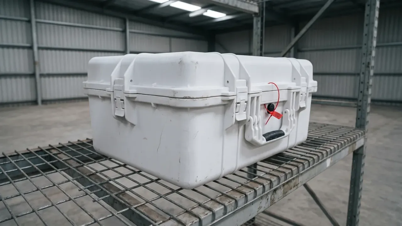
Quick answer: Industrial valve & actuator transit protection case: 780×520×420 mm, a φ210 mm relief cavity with 8 mm axial margin, 24 kg empty, two DN100 valves.
Table of contents
- Clamping a Valve Body in an Industrial Valve & Actuator Transit Protection Case
- Relief Cavities for Flange Faces and Actuator Bosses
- Axial Stops and Radial Anti-Rotation
- Lifting Hole Position and the Sling Point
- Lashing Against Tip-Over on Long Road Hauls
- FAQ
1. Clamping a Valve Body in an Industrial Valve & Actuator Transit Protection Case
A valve is rarely damaged by weight; the flange face is ruined first, a ring of scratches from another part. The load is asymmetrical: a DN100 flange of 220 mm, eight M16 holes on a 180 mm bolt circle, an actuator to one side. Inside 720×460×360 mm, wall 6.0 mm, 24 kg empty, two bays of 360 mm.
Three constraints follow. The sealing face is the datum, so nothing may press on it; the terminal box stands proud and splits first; the stem wears oval under side force. An industrial valve & actuator transit protection case can only relieve and stop, never clamp.
That is why the cavity runs 720 mm long: two valves at 360 mm each, no clamp between them, and a machined EVA cavity taking the load.
2. Relief Cavities for Flange Faces and Actuator Bosses
The relief cavity is φ210 mm wide and 128 mm deep, matched to a 120 mm actuator protrusion, which leaves 8 mm of axial margin. The flange measures 220 mm, ten millimetres wider than the cavity mouth, so it never enters; it seats on a ring cut into the 40 mm EVA.
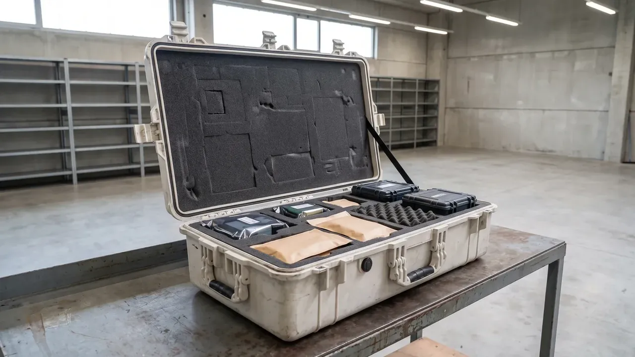
| Relief cavity | Size | Load path and failure mode |
|---|---|---|
| Actuator cavity | φ210 mm, 128 mm deep | Takes axial margin only; too little and it splits the liner |
| Flange seat ring | 220 mm outer, 45 mm wide | Carries the valve weight, collapses past 30% compression |
| Bolt hole clearance | 8 × M16, 18 mm holes | A 2 mm shift lands the ring on a stud end |
In an industrial valve & actuator transit protection case, EVA at 45 to 70 kg/m³ gives 30 to 70 kPa at 25% compression. One valve of 38 kg over a 0.029 m² ring is 12.8 kPa, under half the low end, so the pad stays barely compacted.
3. Axial Stops and Radial Anti-Rotation
Four axial stops, two per valve, press on 30×20 mm pads at the flange back and hold the valve against the ring. Stop height follows the 20 mm flange; half a millimetre high and it misses, low and it never loads.
| Axial stop | Execution | What shows when it is out |
|---|---|---|
| Stop block | 4 pieces, 30×20 mm pads | One missing and the valve slides 6 mm |
| Anti-rotation pin | φ12 mm through two 18 mm holes | Bore worn to 13 mm lets the body turn 2° |
| Lid pad | EVA thickened from 40 mm to 55 mm | Too thick, closing force passes 480 N |
Radial location comes from the φ12 mm pin through two opposite bolt holes. At 3 mm per side the body turns about 2°, and at that point the terminal box touches the bay wall.
When a 120 mm actuator meets 8 mm of margin, the stop blocks of this industrial valve & actuator transit protection case crack the liner first, and the lid closes with a 3 mm gap at the rim.
4. Lifting Hole Position and the Sling Point
Four φ30 mm lifting holes in the industrial valve & actuator transit protection case sit on thickened corners 60 mm above the base, below the centre of gravity so the case does not roll in the sling. Sling offset measures from the diagonal crossing point to the loaded centre of gravity.
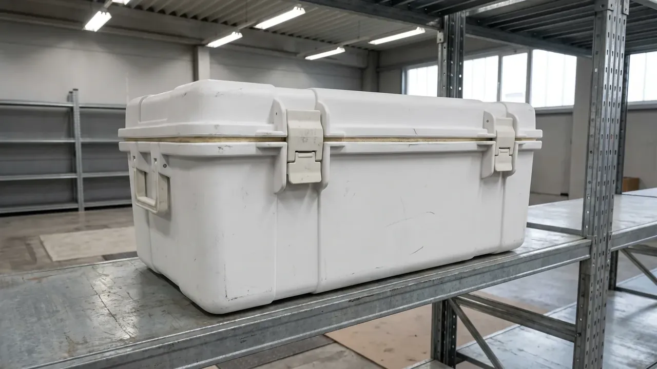
With the actuator to one side the loaded centre of gravity moves 18 mm that way. Symmetrical holes give an 18 mm offset, inside the 25 mm limit; two valves facing the same way stack it to 30 mm and one corner lifts first.
| Sling offset | Value | Behaviour on the hook |
|---|---|---|
| Symmetrical holes | 18 mm | All four corners lift together |
| One-side load | 25 mm limit | One corner rises, the rim gap opens 1 mm |
| Both facing one way | 30 mm over | 3° of tilt, the loaded strap doubles |
The two 120×60 mm forklift pockets suit a hand pallet truck. At 60 mm clear height only a 50 mm blade fits, while a counterbalance fork needs 95 mm, so the 24 kg empty case rides the pallet truck and the 100 kg loaded case goes on the sling.
5. Lashing Against Tip-Over on Long Road Hauls
An 800 km road leg becomes 133 min on the table: severity level II of the road spectrum runs 0.58 g rms, and test time is distance over 6 km/min. Only after that run do the stop pads and the pin show polish.
Stacked 2 high, the industrial valve & actuator transit protection case below carries 100 kg above it. Six latches at 480 N give 2880 N, enough for that load, and the margin belongs to the strap peak rather than to stacking.
Two 25 mm straps cross the middle and tie the case to the pallet. Four 40 mm feet drop into the pallet grid and lock it sideways; the straps hold vertically.
The industrial valve & actuator transit protection case reaches IP66 with a 12.5 mm nozzle at 100 L/min for 3 min. From −25 ℃ loading to +60 ℃ inside a trailer, the gasket must stay compressed at both ends.
Conclusion
The difficulty in an industrial valve & actuator transit protection case starts at the flange: a φ210 mm relief cavity, 8 mm of axial margin, four stop blocks and four φ30 mm lifting holes hold an asymmetrical casting inside a 780×520×420 mm shell. After 800 km of road, 133 min on the table, the pads and the pin are only starting to wear. Which way the valves face decides more about arrival than extra wall thickness.
Related Reading
- Case Type Choice for Heavy Export Parts
- Volume Estimation for Odd-Shaped Parts
- Pressure Relief Valve Opening Point
Related Products
- 8 Series — Gun Cases; Military Equipment Cases; Camera Equipment Cases; Drone Cases; Watch Cases; Knife Cases; First Aid Cases; Electronics Equipment Cases
- WL8-2812 PP Gun Case — model WL8-2812
- All protective cases and toolboxes: 7 series, 158 models