

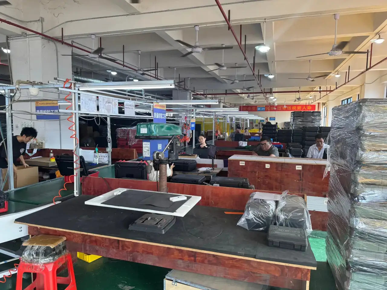
Quick answer: An injection molded protective case is specified upward from the load, never inward from an outer size. Payload weight and cavity allowance come first; wall thickness, ribs, latches and stacking load then settle into one set of numbers that survive a drop and a four-high stack.
Table of contents
- Load List First, Cavity Second
- From Cavity to Outside: Where 18 mm Comes From
- 72 kg on Four Ribs: Load and Stacking
- Wall, Ribs and Mould Temperature Together
- FAQ
1. Load List First, Cavity Second
Weigh the payload, measure the longest item, then talk about a cavity. The inside of an injection molded protective case is pushed out by three facts: an 18 kg kit, a longest piece of 1.1 m, and the finger room a gloved hand needs. Weight sets the wall bracket, the longest item sets length and width, the handling gesture sets height.
Allowance follows how the kit sits. Loose with foam, 10 mm per side. Die-cut location, 6 mm. Long items standing upright, 15 mm plus 20 mm of extra height. Too generous and the case grows fat; too tight and compressed foam lifts the lid off the gasket.
For that kit the cavity of the injection molded protective case settles at 1180 × 380 × 175 mm. Every other dimension is a function of it.
Order is where projects fail. A team picks an outer size first, stuffs a liner inside, and finds the foam down to 8 mm, so the contents strike the wall on the first drop. The workable sequence is to lay the load list open: unit count, unit size, total mass, centre of gravity, pick-up gesture. Anything absent from that list should not be filled in from habit. If the centre of gravity sits left, the cavity needs a reinforced rib zone on the left. If the case travels upright, the handle must land above that centre.
2. From Cavity to Outside: Where 18 mm Comes From
Once the cavity is fixed, a wall figure, rib and flange height, and draft compensation decide the outside.
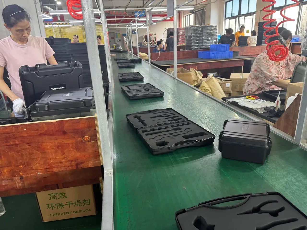
Take 3.0 mm wall, 12 mm rib height, 3 mm for flange and tongue-and-groove. That totals 18 mm. A 1180 mm cavity plus two allowances lands at 1216 mm outside; width 380 becomes 416; height 175 becomes 211.
Thicker is not safer. Three millimetres is the balance point for polypropylene between dead weight, stacking and drop resistance. At 2.4 mm the rim whitens by the third lid closure; at 4 mm a case passes 9 kg and cooling nearly doubles.
Ribs hold a thin wall in shape: height 12 mm, root 2.6 mm, spans under 160 mm. Past 0.9 times the wall, a root draws a sink mark no bead blasting hides.
| Cavity L×W×H (mm) | Wall (mm) | Allowance per side (mm) | Outside (mm) | Case weight (kg) |
|---|---|---|---|---|
| 620 × 300 × 140 | 2.6 | 15 | 650 × 330 × 170 | 3.2 |
| 900 × 360 × 160 | 3.0 | 18 | 936 × 396 × 196 | 5.1 |
| 1180 × 380 × 175 | 3.0 | 18 | 1216 × 416 × 211 | 7.4 |
3. 72 kg on Four Ribs: Load and Stacking
Loaded at 24 kg and stacked four high, the bottom injection molded protective case carries 72 kg. The load does not spread evenly across four ribs; the middle of the base has no support, so the paths run through the corners and two cross members.
The acceptance figure is a static 300 kg held 24 hours with base flatness moving under 2 mm.
| Loaded case (kg) | Typical stack | Bottom load (kg) | Suggested wall (mm) | Ribs |
|---|---|---|---|---|
| 12 | 5 high | 48 | 2.6 | 4 |
| 24 | 4 high | 72 | 3.0 | 4 |
| 35 | 3 high | 70 | 3.4 | 6 |
Retention is designed at 320 N; under 260 N a loaded case pops open on impact. Hinge torque of 1.8 N·m stops the lid slamming on fingers without a two-handed lift.
4. Wall, Ribs and Mould Temperature Together
A specification sheet holds static numbers; on a mould they must be negotiated with temperature and time. Across the same outer shape, an 8 ℃ gap between cavity and core shifts base flatness by 1.5 mm, so the case rests on four corners when stacked.
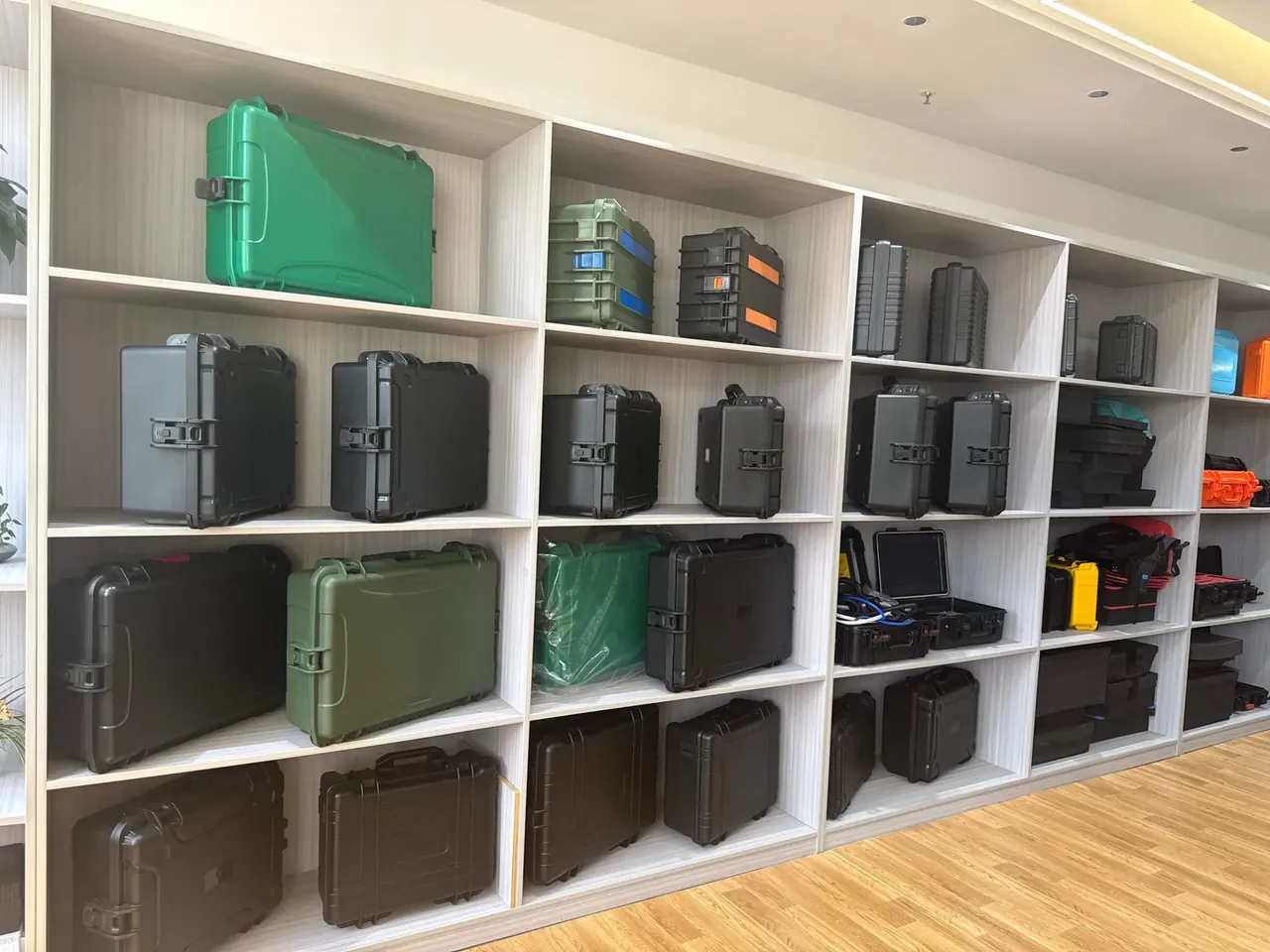
Tune along five lines:
- Wall 3.0 mm at ±0.15 mm tolerance; thinner cracks at the latch seat first.
- Rib root 2.6 mm, height 12 mm; a root past 0.9 times the wall becomes a double rib.
- Mould temperature 55 ℃, cavity-to-core difference under 6 ℃.
- Cooling 24 seconds, the floor for a 3 mm wall; three seconds less leaves white ejector marks.
- Latch seats thickened to 3.6 mm so stress leaves the thin wall.
Put those five into a process card and the injection molded protective case stops drifting between batches; the first-off sample closes the loop with a feeler gauge on the parting line.
Conclusion
Read as one chain, the four anchors leave few free choices: load list to cavity, 18 mm per side to outside, stacking to wall and rib count, wall to mould temperature and cooling. Skip a link and the bill arrives as sink marks, warped bases or collapsed stacks. Written into a table and a process card, these numbers give buyer and toolmaker a shared way to specify an injection molded protective case.
This article discusses only the container (case body) side of specifications and design intent, and does not cover any handling, loading or use of the contents.
Related Reading
- Inside the moulding cycle of a protective case
- Comparing two cases of the same footprint
- Wall thickness and load brackets for heavy duty work
Related Products
- 8 Series — Gun Cases; Military Equipment Cases; Camera Equipment Cases; Drone Cases; Watch Cases; Knife Cases; First Aid Cases; Electronics Equipment Cases
- WL8-2812 PP Gun Case — model WL8-2812
- All protective cases and toolboxes: 7 series, 158 models