

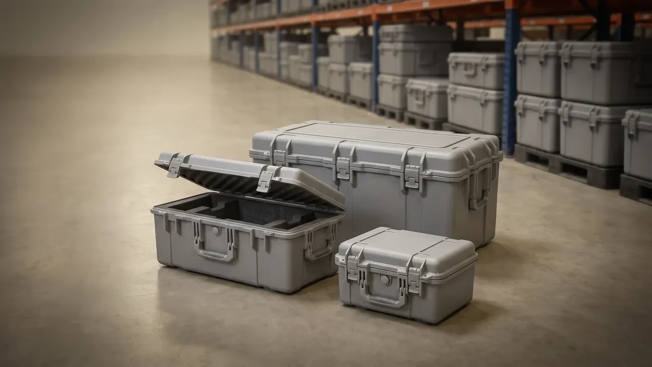
Quick answer: Size the cavity from the stowed arm posture, the base from the loaded weight, the foam from the drop test. A 165 kg six-axis unit with 2650 mm reach folds to about 1450 by 900 by 1200 mm and must stay under 40G on an 800 mm drop.
Table of contents
- Sizing the Robot Protective Case to the Stowed Arm Posture
- Load Rating and Stacking Decide the Base
- Foam Density and Drop G-Values
- Sealing Class and the Wet Environment
- Lifting and Unpacking Flow
- FAQ
1. Sizing the Robot Protective Case to the Stowed Arm Posture
Measure the machine folded, not the floor drawing. With axis two at 30 degrees, axis four folded back and the tool flange pointing down, a 165 kg arm with 2650 mm reach occupies about 1450 by 900 by 1200 mm.
Add 30 mm per side for foam, and take positioning from the base: four M16 bolts through locating blocks on a 200 mm circle, heads sunk 5 mm below the foam.
| Decision point | Number to lock | How to check |
|---|---|---|
| Cavity | Envelope plus 30 mm per side | Cardboard template at the real posture |
| Positioning | 4 x M16 on flange pitch | Feeler gauge at the block face |
| Wall | 6 mm rotomoulded, double lip | Ultrasonic gauge, six points |
2. Load Rating and Stacking Decide the Base
For a robot protective case the bare arm is 165 kg, the tool and cables add 40 kg, so the working load is 205 kg. A 2.5 dynamic factor puts 510 kg on the base: 18 mm plywood over steel cross members at 300 mm centres, with a 4 mm plate at each caster mount.
Stacking is usually left out. Three tiers means the bottom case carries 560 kg, and a 1.5 safety factor lifts that to 840 kg; a robot protective case with a 6 mm wall holds lid deflection under 3 mm, while 4.5 mm without ribs sags at two tiers. Casters are 150 mm polyurethane, 300 kg dynamic each, two swivel with brakes.
3. Foam Density and Drop G-Values
Inside a robot protective case, damage comes from deceleration. At 800 mm with 30 mm of foam the peak should stay under 40G; at 20 mm it passes 70G, where the gearbox output shaft is most exposed.
EPDM at 45 kg per cubic metre carries about 90 kPa at 25 percent compression and returns with under 10 percent set. Use 50 mm at the base, 30 mm on the sides, 25 mm in the lid, at densities of 55, 45 and 35.
| Zone | Thickness | Density | Job |
|---|---|---|---|
| Base | 50 mm | 55 kg/m3 | Absorb the drop |
| Sides | 30 mm | 45 kg/m3 | Stop lateral travel |
| Lid | 25 mm | 35 kg/m3 | Hold the top down |
Cutouts run 2 mm interference, CNC routed to plus or minus 1 mm. Add 500 g of desiccant so humidity stays below 40 percent.
4. Sealing Class and the Wet Environment
A robot protective case meets both a machine shop and a sea freight box. A Shore 55A silicone gasket of 8 mm section, compressed 30 percent against a double lip, gives IP67: 30 minutes at one metre, dry inside. Salt spray is verified at 480 hours, so hinges and latches are 304 stainless.
A 1200 mm case needs four cam latches at 350 mm centres; stretch to 500 mm and the gasket lifts midway. Ten cycles from minus 25 to 60 degrees Celsius leave silicone under 0.5 mm of set, while nitrile measures 1.5 mm and leaks by the second cycle.
5. Lifting and Unpacking Flow
Loaded, the robot protective case weighs 273 kg, so lifting points belong on the drawing: four corner eye bolts rated 1.2 t, sling angles at or below 60 degrees, fork pockets at 120 mm high and 60 mm deep.
Hinges on the long side open to 105 degrees on two 300 N gas struts, and stainless pins in self-lubricating bushes add under 0.3 mm of play after 5000 cycles.
| Handling | Interface | Limit | Watch out |
|---|---|---|---|
| Crane | 4 eye bolts | 1.2 t per point | Guards at 60 degrees |
| Forklift | Pockets 120 x 60 mm | Forks 1.2 m or longer | Seat fully, lift level |
Conclusion
The order is fixed: cavity from the posture, base from the dynamic factor, foam from the G-value, seal from the shipping route, lifting from the loaded weight. Written into the drawing and the acceptance clause, those five numbers make quotations comparable. Settle the structure first, and the robot protective case closes, carries and stays dry.
This article discusses only the container (case body) side of specifications and design intent, and does not cover any handling, loading or use of the contents.
Related Reading
- Reading the limits of heavy-duty case specifications
- Case size ranges and internal clearance
- Rotomoulded versus injection-moulded case bodies
- How internal dividers and foam are specified
Related Products
- 8 Series — Gun Cases; Military Equipment Cases; Camera Equipment Cases; Drone Cases; Watch Cases; Knife Cases; First Aid Cases; Electronics Equipment Cases
- WL8-2812 PP Gun Case — model WL8-2812
- All protective cases and toolboxes: 7 series, 158 models